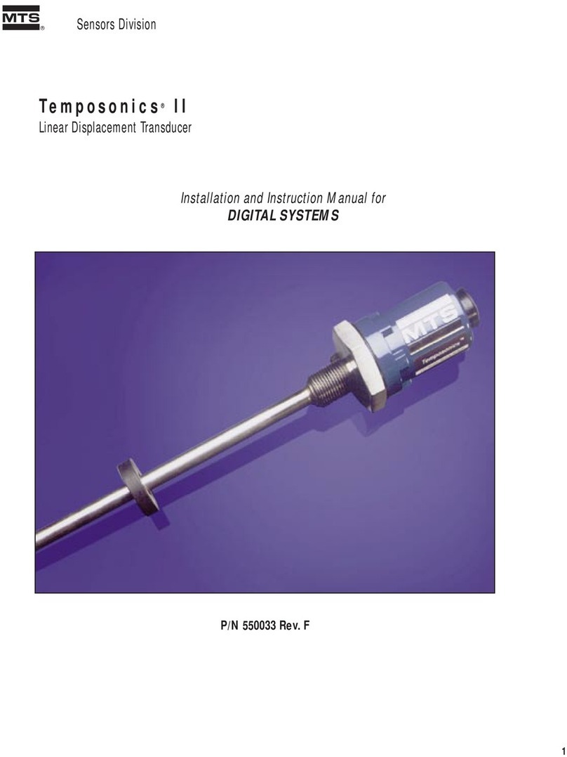
MTS Systems Temposonics II LDT Service manual

l
Temposonics
®
Position Sensors and Systems
Part No. 550033 Rev. E
Temposonics®II
Position Sensors
Installation & Instruction
Manual for Analog Systems
11-98 550032 Revision F

GENERAL INFORMATION
MTS PHONE NUMBERS
Application questions: 800-633-7609
Repair Service: 800-248-0532
Fax: 919-677-0200
SHIPPING ADDRESS
MTS Systems Corporation
Sensors Division
3001 Sheldon Drive
Cary, North Carolina 27513
HOURS
Monday - Thursday
7:30 a.m. to 6:30 p.m. EST/EDT
Friday
7:30 a.m. to 5:00 p.m. EST/EDT

TABLE OF CONTENTS
Section Page
1 INTRODUCTION 1
1.1 Theory of Operation/Magnetostriction 1
1.2 Temposonics II LDT Specifications for Sensors <180 Inches 2
1.3 Temposonics II LDT Specifications for Sensors ³180 inches 2
2 TEMPOSONICS II LDT INSTALLATION 3
2.1 Types of Transducer Supports 5
2.1.1 Loop Supports 5
2.1.2 Channel Supports 6
2.1.3 Guide Pipe Supports 6
2.2 Open Magnets 7
2.3 Spring Loading and Tensioning 7
2.4 Cylinder Installation 7
2.5 Installing Magnets 10
3 TEMPOSONICS II WIRING 11
4 TROUBLESHOOTING THE LINEAR DISPLACEMENT TRANSDUCER 12
5 GROUNDING 13
6 INTRODUCTION TO ANALOG SYSTEMS 14
6.1 Specifications of Analog System Components 15
6.1a Analog Personality Module (APM) 15
6.1b Analog Output Module (AOM) and Analog Output Card 15
7 ANALOG PERSONALITY MODULE 16
7.1 Performance Modes 16
7.2 APM Programming Procedure 18
8 INSTALLING THE ANALOG OUTPUT MODULE (AOM) 21
9 ANALOG OUTPUT MODULE ADJUSTMENTS 22
9.1 Nominal Range of Adjustments 22
9.2 Null and Full-Scale Adjustments 23
9.3 Velocity Null Adjustments 24
10 ANALOG OUTPUT MODULE/WIRING PROCEDURES 25
10.1 Preparing Cable for Connection to the AOM 25
10.2 J1 Installation Wiring 26
10.3 J1 Connections for AOM 27
10.4 J1 Connection to AOM with MS Connectors 29
10.5 J1 Connections 29
11 TROUBLESHOOTING THE ANALOG OUTPUT MODULE 32
11.1 General 32
11.2 Power Supply Check 32
11.3 Grounding 33
11.4 Connections 33
11.5 LDT Signals 33
12 ANALOG OUTPUT CARD 36

1
1. Introduction to the Temposonics II Linear Displacement Transducer (LDT)
The Temposonics II LDT precisely senses the position of an external magnet to measure displacement with a
high degree of accuracy and resolution. Using the principle of magnetostriction (see Section 1.1, below), the
Temposonics II LDT measures the time interval between the initiation of an interrogation pulse and the detection
of a return pulse. A variety of interface devices use the data derived from these two pulses and generates an analog
or digital output to represent position.
1.1 Theory of Operation/Magnetostriction
The interrogation pulse travels the length of the transducer by a conducting wire threaded through a hol-
low waveguide. The waveguide is spring loaded within the transducer rod and exhibits the physical prop-
erty of magnetostriction. When the magnetic field of the interrogation pulse interacts with the stationary
magnetic field of the external magnet, a torsional strain pulse or “twist” is produced in the waveguide.
This strain pulse travels in both directions, away from the magnet. At the end of the rod, the strain pulse
is damped within the “dead zone”. At the head of the transducer, two magnetically coupled sensing coils
are attached to strain sensitive tapes. The tapes translate the strain pulse through coils to an electrical
“return pulse”. The coil voltage is then amplified in the head electronics before it is sent to various mea-
suring devices as the conditioned “return pulse”.
Figure 1-1
Waveguide Interaction
Reference
magnetic field
Conducting element
Interaction of magnetic
fields causes
waveguide to twist
Magnetic field from interrogation pulse
Waveguide
twist
Waveguide Sensing coil
Bias magnet
Strain tape
External reference magnet
Waveguide enclosure

2
1.2 Temposonics II LDT Specifications for Sensors <180 Inches
Parameter Specifications
Input Voltage: ± 12 to ± 15 Vdc
Current Draw: Transducer Only:
± 15 Vdc at 100 mA maximum, 25 mA minimum
(current draw varies with magnet position, maximum draw occurs when magnet is at 2 in.
(50.6 mm) from the flange and minimum update time is being utilized)
Transducer with:
• Analog Personality Module (APM):
± 13.5 Vdc to ±15 Vdc at 190 mA maximum, 115 mA minimum
• Analog Output Module (AOM):
+ 15 Vdc at 250 mA, -15 Vdc at 65 mA
Displacement: Up to 25 feet (7620 millimeters)
Dead Zone: 2.5 inches (63.5 millimeters) for stroke lengths up to 179.9 in.
Electronics Enclosure: IP-67
Non-linearity: < ± 0.05% of full scale or ± 0.002 inch (±0.05 mm), whichever is greater
Resolution:
1 ÷ [gradient x crystal freq. (mHz) x circulation]; maximum resolution: 0.006 mm or 0.00025 in.
Repeatability: Equals resolution
Hysteresis: 0.0008 inch (0.02 mm) maximum
Update Time: Resolution and Stroke dependent
Minimum = [Stroke (specified in inches) + 3] x 9.1 µs
Operating Temperature
Head Electronics: - 40 to 150°F (- 40 to 66°C)
Transducer Rod: - 40 to 185°F (- 40 to 85°C)
Operating Pressure: 3000 psi continuous, 8000 psi static
Analog Outputs (absolute) Standard 0 to10 Vdc (other voltage outputs are available)
Optional: 4-20 mA (AOM)
Specifications are subject to change without notice. Consult MTS for verification of specifications critical to your application.
1.3 Temposonics II LDT Specifications for Sensors ³180 Inches
Below is a list of specifications that pertain to Temposonics II transducers with active stroke lengths of
180 inches (5083 mm) to 300 inches (7620 mm). The below specifications apply only to sensors 180 to
300 inches in length. Specifications not listed below may be found in section 1.2, above.
Parameter Specification
Parameter Specifications
Input Voltage: • Maximum: ± 15 Vdc, ± 5% at 100 mA
• Minimum: ± 15 Vdc at 25 mA
(current draw varies with magnet position, maximum draw occurs when magnet is 2 inches
(50.8 mm) from the flange and minimum update time is being used)
Dead Zone: 3 in. (76.2 mm)
Cable Length: • Maximum cable length for neuter version transducer (i.e., Temposonics II without an
integrated Personality Module) which requires the use of external interface electronics
(Analog Output Module, Digital Interface Box or other signal conditioners) is 250 ft.
• APM: 150 ft.
AOM: 250 ft.
Magnet Requirement: Part Numbers: 201554, 201553, 251416, 201542
Specifications are subject to change without notice. Consult MTS for verification of specifications critical to your application.

3
2. Temposonics II LDT Installation
Before beginning installation, be sure you know the following dimensions (as illustrated in Figures 2-1 to 2-3a-c.):
• Null Space
• Stroke
• Dead Zone
Figure 2-1
Temposonics II Dimensions
Figure 2-2
Temposonics II Connector/Cable Clearance Requirements
Temposonics II with
Molded Connector/Cable Assembly
Temposonics II with
Field Instalable Connector
Temposonics II with
Integral Cable
2.5 in. minimum
(clearance for connector
and cable bend)
1.25 in.
minimum
3/4-16 UNF-3A Thread
0.38 in. DIA
(9.65 mm)
Standard Null
(2.0 in., 50 mm)
0.38 in. (9.65 mm)
1.36 in.
(34.54 mm)
End Plug,
Flush 0.375 in.
(9.65 mm)
0.03 in. (0.76 mm)
Hex
1.75 in. (44.45 mm) across flats
2.13 in.
(54 mm)
Flange to Tip
Stroke Length
(specified by customer)
1.57 in. dia.
(39.87 mm)
1.75 in. dia.
(44.45 mm)
2.50 in.
(63.50 mm)
Dead Zone
2.50 in.
(63.50 mm)
for stroke
lengths up to
179.9 in;
3 in. (76.2 mm)
for strokes
³180 in.

4
1. Use the 3/4 inch (19 mm), 16 UNF thread of the transducer to mount it at the selected location. Leave room
to access the hex head. If a pressure or moisture seal is required, install an O-ring (type MS 28778-8 is
recommended) in the special groove. Use the hex head to tighten the transducer assembly.
2. Install the permanent magnet over the LDT rod. Mount the permanent magnet to the movable device whose
displacement will be measured. To minimize the effect of magnetic materials (i.e. iron, steel, etc.) on the
magnetic field of the permanent magnet, ensure the minimum spacing requirements are met as shown in
Figures 2-3a-c. (Any non-magnetic materials can be in direct contact with the permanent magnet without affect-
ing performance.)
Figure 2-3a
Minimum Magnet Clearance Using Magnetic Supports
Figure 2-3b Figure 2-3c
Minimum Null Space Using Non-Magnetic Support Minimum Null Space Using Magnetic Support
NOTES:
1. The magnet must not contact ferromagnetic materials (such as iron or steel). Clearances are required between the surface of the magnet
and ferromagnetic material, as shown. Non-ferrous material (such as copper, brass, or 300 series stainless steel) may contact the magnet
without affecting transducer performance.
2. Standard Null Space is 2 inches. There is no maximum limit for Null Space. Less then 2 inches can be specified if magnet clearances meet
requirements illustrated above.
5/8 in.
Minimum
Ferromagnetic Support
Magnet
A = 5/8 in. plus support thickness
A
NON-Ferromagnetic Support
Magnet
A = 1 in., minimum to clear threads
Threads
A
1/8 in.
Minimum 5/8 in.
Minimum
Magnet
Tip Head
Ferromagnetic Material
1/8 in.
Minimum

5
3. Move the permanent magnet full-scale to check that it moves freely. If not (if the magnet rubs on the transduc-
er) you can correct this by mounting a support bracket to the end of the transducer. Long transducers may
need additional supports to be attached to the transducer rod. Transducer supports are described later in this
section.
2.1 Types of Transducer Supports
Long transducers (48 inches or longer) may require supports to maintain proper alignment between the
transducer rod and the permanent magnet. When transducer rod supports are used, special, open-ended
permanent magnets are required.
Transducer supports attached to the active stroke length must be made of a non-ferrous material, thin
enough to permit the permanent magnet to pass without obstruction. Because the permanent magnet
does not enter the dead zone, supports connected within the dead zone may be made of any material.
The main types of supports are loop, channel, and guide pipe supports.
2.1.1 Loop Supports
Loop supports are fabricated from non-ferrous materials, thin enough to permit free movement of
the magnet. Loop supports are recommended for straight transducers and may be spaced apart
approximately every three feet. They may be used alone or with channel supports. Figure 2-4
illustrates the fabrication of a loop support.
Figure 2-4
Loop Support
NOTE:
When open magnets are used, ensure the
transducer rod remains within the inside
diameter of the magnet throughout the
length of the stroke. If the transducer rod
is allowed to enter the cut out area of an
open magnet, the transducer signal
could attenuate or be lost. See Figure 2-7.
TransducerRod
0.375in.
I.D.
FrontView
Side View
NOTE:
Clearance between the magnet and the
transducer rod is not critical. However,
contact between the components will
cause wear over time. The installation of
supports or readjustment of the supports
is recommended if the magnet contacts
the transducer rod.
0.38 in.
I.D.

6
2.1.2 Channel Supports
Channel supports, being typically straight, are normally used with rigid transducers. A channel
support consists of a straight channel with loop supports mounted at intervals. The loop supports
are required to keep the transducer within the channel. Figure 2-5 shows a channel support.
Channel supports are available from various manufacturers or may be fabricated.
Figure 2-5
Channel Support
2.1.3 Guide Pipe Supports
Guide pipe supports are normally used for flexible transducers. A guide pipe support is construct-
ed of non-ferrous material, straight or bent to the desired shape. As shown in Figure 2-6, both
inside and outside dimensions of the pipe are critical:
• Because the transducer rod is installed inside the pipe, the inside diameter of the pipe must be
large enough to clear the rod.
Figure. 2-6
Guide Pipe Support
• The outside diameter of the pipe must be small enough to clear the magnet.
Refer to pipe manufacturers’ specifications and dimensions (schedule 10, 40, etc.) to select the
appropriate size pipe. Guide pipe is typically supported at each end of the pipe.
Magnet
• Part No.: 201553 or
• Part No.: 251416
Guide Pipe
Rod
Magnet
• Part No.: 201553 or
• Part No.: 251416
Loop Support
Rod

7
2.2 Open Magnets
When using an open magnet, make sure the rod is positioned at all times within the “active” zone of the
magnet. The transducer cannot operate properly unless the entire stroke of the transducer rod is located
within this zone. The active zone, as shown in Figure 2-7, lies within the inside diameter of the magnet.
Figure 2-7
Active Zone for Open Magnets
2.3 Spring Loading or Tensioning
The transducer rod can be spring loaded or tensioned using a stationary weight. Attach a spring mecha-
nism or weight to the dead zone of the transducer rod with a clamping device which will not deform the
transducer rod. The maximum weight or spring tension is 5 to 7 lbs.
2.4 Cylinder Installation
Figure 2-8
Typical Cylinder Installation
Null (as specified)
Minimum: 2 in. (50mm)
NON-ferrous Spacer, Part No.: 400633
Magnet, Type SR-12
Part No.: 201542
(1.29 in. (32.76 mm) O.D.
(other options available)
Chamfered Rod Bushing
1
5
2
O-ring (MS 28778-8 or equivalent)
Part No.: 560315
Piston Head and Rod Assembly
4
0.5 in (12.7 mm) Bore
Active Stroke
3
Minimum: 5 in. (127 mm)
Dead Zone:
2.50 in. (63.5 mm)
for stroke lengths
up to 179.9 in;
3 in. (76.2 mm)
for stroke lengths
³180 in.
Pipe O.D. 0.38 in.
1/8 in.
min.
Inactive Zone
Active Zone
Magnet

8
Figure 2-8 shows a typical cylinder installation. Review the following before attempting this type of
installation.
• Use a non-ferrous (plastic, brass, Teflon®, etc.) spacer [1] to provide 1/8 inch (32 mm) minimum space
between the magnet and the piston.
• An O-ring groove [2] is provided at the base of the transducer hex head for pressure sealing. MTS uses
mil-standard MS33514 for the O-ring groove. Refer to mil-standard MS33649 or SAE J514 for machining
of mating surfaces.
• The null space [3] is specified according to the installation design and cylinder dimensions. The analog
output module provides a null adjustment. Make sure that the magnet can be mounted at the proper
null position.
• The piston head [4] shown in Figure 2-8 is typical. For some installations, depending on the clearances,
it may be desired to countersink the magnet.
• A chamfered rod bushing [5] should be considered for stokes over 5 feet (1.5 meters) to prevent wear
on the magnet as the piston retracts. The bushing should be made from Teflon or similar material.
• The recommended bore for the cylinder rod is 1/2 inch (13 mm). The transducer rod includes a 0.375
inch (9.53 mm) diameter end plug mounted flush. Use standard industry practices for machining and
mounting of all components. Consult the cylinder manufacturer for applicable SAE or military specifica-
tions.
Figure 2-9
O-ring Boss Detail
2.250 in. Minimum Dia
Specifies Surface B
0.875 in. Dia.
+.0.015
-0.000
0.769 in. Dia.
+.0.015
-0.000
120°±0°30'
0.094 in. +.0.015
-0.000
1.105 in.
Minimum
Full Thread
Depth See Detail C
3/4-16 UNIF-3B Thread
See Notes 3 And 4
0.500
Dia.
Blind Thread Design 45°±5°
See Note 7
See Detail C
3/4-16 UNJF-3B Thread
See Notes 3 and 4
Thru Thread Design
120°±0°30'
2.250 in. Minimum Dia
Specifies Surface B
0.094 in. REF
See Note 8
0.030 in. ±0.010 R
Detail C
NOTES:
1. Dimensions and tolerances based on ANSI Y14.5-1982.
2. MTS has extracted all pertinent information from MS33649 to Generate this document.
3. PD must be square with surface B within 0.005 FIM across 2.250 dia minimum.
4. PD must be concentric with 2.250 dia within 0.030 FIM and with 0.769 dia within 0.005 FIM.
5. Surface texture ANSI B46.1-1978
6. Use o-ring MTS part number 560315 for correct sealing.
7. The thread design shall have sufficient threads to meet strength requirements of material used.
8. Finish counter-bore shall be free from longitudinal and spiral tool marks. Annular tool marks up to 32 micro-
inches maximum will be permissible.
Key:
FIM=FullIndicatorMovement
PD = Pitch Diameter
0.020 in. R
Maximum
32 min.
32 min.
125 min. 125 min.
0.875in. Dia.
+.0.015
-0.000
0.769in. Dia.
+.0.015
-0.000
32 min.
32 min.
0.094in. +.0.015
-0.000
- B - - B -
0.005 in. Dia., FIMA 0.005 in. Dia., FIMA

9
Figure 2-10
Port Detail (SAE J1926/1)
NOTES:
1. If face of port is on a machined surface, dimensions 1.180 and 0.094 need not apply as
long as R0.008/0.004 is maintained to avoid damage to the O-ring during installation.
2. Measure perpendicularity to A at this diameter.
3. This dimension applies when tap drill cannot pass through entire boss.
4. This dimension does not conform to SAE J1926/1.
1.100 in.
See Note 4 1.250 in.
See Note 3
See Note 4
ø0.500 in.
Ref.
See Note 4
1.180 in.
Recommended
Minimum
Spotface
Diameter
See Note 1
45°±5°
15°±1°
0.094 in. Max.
R0.015 in.
Max.
0.008 in.
0.004 in.
Pitch
Dia.
0.125 min.
0.125 min.
3/4-16 UNF-2B Thread
ø0.866in.
Minimum
See Note 2
R
ø0.813 in.
±0.002 in.
0.106 in.
±0.008 in.
A
0.008 A
0.004 A

10
2.5 Installing Magnets
Figure 2-11 below shows the standard magnet types and dimensions. The circular magnet with an outside
diameter of 1.29 inches and 0.53 inch inside diameter (Part No. 201542) is the most common and is suit-
able for most applications. Larger magnets, with an outside diameter of 2.5 inches are typically only used
with Temposonics transducers that exceed 180 inches in stroke length. Magnets with a 90 degree cut-out
are used in applications that require intermediate supports along the transducer rod.
If upon installation, the null adjustment is inadequate, you can design a coupler with adjustments to
mount the magnet to the measured member.
Figure 2-11
Magnet Dimensions
Part No. 400633
Part No. 201554
1 of 4 holes
each 0.182 in. dia. (4.6 mm)
on 1.625 in. dia. (41.3 mm)
I.D.: 0.75 in. (19.05 mm)
O.D.: 2.49 in. (63.25 mm)
Thickness: 0.375 in. (9.5 mm)
Part No. 201553
1 of 2 holes
0.177 in. dia. (4.5 mm)
120°apart
on 1.625 in. dia. (41.3 mm)
0.44 in. (11.2 mm) opening
90°cut-out
I.D.: 0.625 in. (15.9 mm)
O.D.: 2.46 in. (63.25 mm)
Thickness: 0.375 in. (9.5 mm)
Part No. 201542
4 holes
each 0.15 in. dia. (3.9 mm)
on 0.94 in. dia. (23.9 mm)
I.D.: 0.53 in. (13.5 mm)
O.D.: 1.29 in. (32.8 mm)
Thickness: 0.312 in. (7.9 mm)
Part No. 400533
I.D.: 0.53 in. (13.5 mm)
O.D.: 1.0 in. (25.4 mm)
Thickness: 0.312 in. (7.9 mm)
I.D.: 0.53 in. (13.5 mm)
O.D.: 1.29 in. (32.8 mm)
Thickness: 0.312 in. (7.9 mm)
1 of 2 holes
0.15 in. dia. (3.9 mm)
120°apart
on 0.94 in. dia. (23.9 mm)
90°cut-out
Part No. 251416
Part No. 401032
I.D.: 0.532 in. (13.5 mm)
O.D.: 0.685 in. (17.4 mm)
Thickness: 0.312 in. (7.9 mm)
For use with stroke lengths
£60 in.
1.1 in.
Ref.
Part No. 251298-1
0.75in.
Ref.
0.80 in.
Ref.
0.52 in.
Ref.
0.30 in. max.
Aluminum Plate
(bonded to magnet)
Magnet Spacer
ID: 14.3 mm (0.563 in.)
OD: 31.75 mm (1.25 in.)
Thickness: 3.175 mm (0.125
4 Holes
each 3.9 mm dia. (0.15 in.)
90°apart on 23.9 mm dia.
(0.94 in.)
S
N

11
3. Temposonics II Wiring
Table 3A
Temposonics II Connections (Neuter Version and with APM)
Temposonics II Integrated Temposonics II Configurations:
or Extension Cable • Neuter - No Personality Module
(see Note 1) • APM - Analog Personality Module
Pin No. Wire Color Code Wire Color Code Neuter APM Option
1 White/Blue Stripe White DC Ground DC Ground
2 Blue/White Stripe Brown Frame Frame
3 White/Orange Stripe Gray Not Used Displacement Return
4 Orange/White Stripe Pink Not Used Displacement Out
5 White/Green Stripe Red +Vdc +Vdc
6Green/White Stripe Blue -Vdc -Vdc
7 White/Brown Stripe Black Output Pulse Return Not Used
8 Brown/White Stripe Violet Output Pulse Not Used
9 White/Gray Stripe Yellow (+) Interrogation (Notes 2, 3) Not Used
10 Gray/White Stripe Green (-) Interrogation (Notes 2, 3) Not Used
NOTES:
1. Verify if the cable has striped or solid color leads and make connections accordingly.
2. 1 to 4 microseconds maximum pulse duration.
3. WARNING: Under no condition should both the positive (+) and negative (-) interrogation leads be connected at the same time
when using the "NEUTER" version Temposonics II transducer. The unused interrogation lead must be connected to DC ground.
4. Temposonics II w/APM requires +/-13.5 to +/-15 Vdc. All others require +/-12 Vdc to +/-15 Vdc.
Temposonics II 10-Pin Connector
(connections styles RB or RC)
Table 3B
Connections - Original Temposonics Transducer
Original Temposonics Wire Color Code Signal Function
Connector Pin Number
AGreen or Gray + 15 Vdc
B Black DC Ground
C Orange or Brown Return Pulse (from LDT)
D Blue - 15 Vdc
E White Interrogation Pulse
F Red + 12 Vdc
1
23579
46810

12
4. Troubleshooting the Linear Displacement Transducer
Use the below checklist when operational problems are encountered. The possible causes of faulty out-
put are listed below in order of probability of occurrence, and should be checked in order.
1. Improper power supply/power connection
2. Mismatched system components*
3. Ground loops/improper grounding*
4. Improper wiring
5. Incorrect receiver device or software*
6. Improper magnet mounting
7. EMI noise, affecting transducer or transducer cable
8. Circuit fault within transducer
* Will cause erratic or unstable output
Figure 4-1
Temposonics II Transducer Signals
(-) Interrogation pulse sent to LDT (Pin 10)
(+) Interrogation pulse sent to LDT (Pin 9)
Return pulse from LDT (pin 8)
1ms1ms1ms
20ms15ms20ms
Update Time
NOTE:
The following checklist is for general
diagnostic purposes. Purchase of replace-
ment components should not be based
solely on this checklist. Consult MTS
Sensors Division for recommendations
and factory service before ordering
replacement components.

5. Grounding
Figure 5-1
Grounding
Figure 5-2 Figure 5-3
4-20mA Grounded Loop 4-20mA Ungrounded Loop
NOTES FOR FIGURES 5-2 & 5-3:
1. Selecting the grounding scheme is dependent upon the controller interface.
2. The current loop path must be completed for the system to operate.
3. The ungrounded loop is not truly isolated from ground. Isolators are required if this configuration is needed by the controller interface.
Customer Interface
250 to
400 W
(max.) 1 - 8 Volts
4-20 mA Ungrounded Loop
+A
V
TB1 B
TB1 A
Analog Output Module
+
100 W
Customer Interface
250 to
400 W
(max.) 1 - 8 Volts
4-20 mA Grounded Loop
+A
V
TB1 B
TB1 A
Analog Output Module
+
Signals Return(s)
Power Return
Frame
Bracket Cover
Cable Shield (no connection)
Head Assembly Grounding Diagram
Signals Return(s)
Power Return
Frame
+Vcc
-Vee
Control Module
(AOM, DIB, Counter Card or other)
(internal to
head enclosure)
Connector
(10 pins)
Ground connection between bracket
and outer cover made by threads
Transducer Rod
(3/8 in. stainless steel)
Machine Ground
Flange
(electrically isolated from threads)
Power Return
Shield Ground
(non current carrying) AC Line
Bracket
Power Supply
Driver/Amplifier
Module
Option Module
13

14
6. Introduction to Analog Systems
Temposonics II Analog Systems include a Linear Displacement Transducer (LDT), a magnet, and an Analog
Personality Module (APM), Analog Output Module (AOM), or an Analog Output Card. See Figures 6-1, 6-2 and 6-
3. The APM, AOM and Analog Output Card generate the interrogation pulse, sense the return pulse, and develop
the analog output displacement signal (voltage or current).
The Analog Personality Module (Figure 6-1) is installed in the electronics enclosure of the Temposonics II trans-
ducer. The Analog Output Module and Analog Output Card are both separate interface devices.
Figure 6-1
Analog System Configuration with Analog Personality Module
Figure 6-2
Analog System Configuration
with Analog Output Module (AOM)
Figure 6-3
Analog System Configuration
with Analog Output Card
POWER SUPPLY
+ 15 Vdc / 250 mA
- 15 Vdc / 65 mA
Analog Displacement Output
Belden YR8105 or equivalent (5 pairs)
T1
T2
Magnet
Temposonics II LDT
ANALOG
OUTPUT
CARD OPTIONAL
24Vdc @ 340 mA
T1
T2
ANALOG
OUTPUT
MODULE
(AOM) J1J2
Analog Displacement Output
Belden YR8105 or equivalent (5 pairs)
POWER SUPPLY
+ 15 Vdc / 250 mA
- 15 Vdc / 65 mA
OPTIONAL
24 Vdc@ 340 mA
Magnet
Temposonics II LDT
APM
Analog Personality Module
USER'S
CONTROL
SYSTEMOutput:
To be specified
Range: - 10 to + 10 Vdc
POWER SUPPLY
±13.5 to ±15 Vdc@ 190 mA
(bipolar)
Magnet
Temposonics II LDT

15
6.1 Specifications of Analog System Components
6.1a Analog Personality Module (APM)
Parameter Specification
Power Requirements: ± 13.5 Vdc to ± 15 Vdc at 190 mA maximum, 115 mA minimum
Output Impedance: 10 K½minimum load for voltage output
Output: Specified by user; Range: - 10 Vdc to + 10 Vdc, forward or reverse acting
Temperature Requirements:
Storage: - 40 to 150°F (- 40 to 70°C)
Operating: - 32 to 150°F (-30 to 70°C)
Coefficient: 10 ppm/°F (18 ppm °C)
Maximum Cable Length: 150 ft.
Standard Features: Field programmable
Specifications are subject to change without notice. Consult MTS for verification of specifications critical to your application.
6.1b Analog Output Module (AOM) and Analog Output Card
Parameter Specification
Power Requirements:
Standard: + 15 Vdc (±2%) at 250 mA, < 1% ripple
- 15 Vdc (±2%) at 65 mA, < 1% ripple
Optional: + 24 Vdc (±2%) at 340 mA, < 1% ripple
Output Impedance: 5 K½minimum load for voltage output, 400½maximum for 4-20 mA output
Velocity Output: 0 to ± 10 Vdc at 1 to 400 in. per second
Positive voltage output as magnet travels away from the transducer's head assembly, negative
voltage output as the magnet travels toward the transducer's head assembly.
Temperature Requirements:
Storage: - 40 to 180°F (- 40 to 82°C)
Operating: - 40 to 180°F (- 40 to 82°C)
Coefficient: 20 ppm/°F (36 ppm/°C)
Standard Features: Non-volatile memory permanently stores set-up information. Surface mounted components
reduce moment of inertia and enhance shock and vibration resistance of the module.
Specifications are subject to change without notice. Consult MTS for verification of specifications critical to your application.

16
7. Analog Personality Module
The Analog Personality Module (APM) is mounted inside the electronics housing of the Temposonics II linear dis-
placement transducer and produces a direct analog output. No additional interfacing electronics are required. The
APM processes digital data into an analog output via a digital to analog converter (DAC). MTS uses a 16-bit DAC
to provide the best available resolution performance.
Typically the APM will be ordered with the Temposonics II transducer. The APM is installed, and the set points
and output voltages are pre-set at the factory.
In the example below (Figure 7-1) we have a 60 inch stroke, note the indicated active stroke range. Set points
cannot be set within the null or dead space area, they can only be set within the active stroke area. The 13 inch
stroke selected in the example is defined by Set Point 1 (set at 4.000 volts) and Set Point 2 (set at 7.538 volts). Set
Point voltage values can range from -10 to +10 Vdc.
Figure 7-1
Voltage & Displacement - 100% Scalable.
7.1 Performance Modes
Update time (or response time) for analog systems is based upon the active stroke of the transducer and
the resolution desired. To get the best mix of update time and resolution for your particular application,
three modes are available with the APM. These modes are as follows:
Resolution-Preferred Mode - In this mode the APM generates a high resolution output while
sacrificing update time. The Resolution Preferred Mode is limited to stroke lengths up to 48 inch-
es and will provide an output resolution of approximately 0.001 inches. In applications exceeding
48 inches, the APM must be set for Balanced Mode or Update Preferred Mode. In the program-
ming procedure, the Resolution Preferred Mode is indicated by an output of 0 volts.
Balanced Mode - In this mode the APM offers a "balance" between update time and resolution.
For stroke lengths up to 250 inches, the output resolution will be approximately 0.003 inches. In
the programming procedure, this mode is indicated by an output of +8.4 volts.
Update Preferred Mode - In this mode the APM produces the fastest possible update time while
sacrificing resolution. For stroke lengths up to 300 inches, the output resolution will be approxi-
mately 0.007 inches. In the programming procedure, this mode is indicated by an output of -8.4
volts.
RPM
60 in.
Set Point 1
4.000 V
Set Point 2
7.538 V
13 in.
2 in.
Null
2.5 in.
Dead
Space 64.5 in.
Available Active Stroke
Stroke can be anywhere within this range
Analog
Personality
Module
SP 1 SP 2

17
The mode desired is selected at the time of order and factory pre-set. The following charts identify the
update time and resolution for each mode.
Resolution
0.000
0.001
0.002
0.003
0.004
0.005
0.006
0.007
0.008
Resolution
(inches per step)
Resolution Preferred Mode
8 16 24 32 40 48
0.000
0.001
0.002
0.003
0.004
0.005 Update Time
8 16 24 32 40 48
Sensor Stroke Length (inches)Sensor Stroke Length (inches)
50 100 150 200 250 300
Resolution
0.003
0.004
0.005
0.006
0.007
Resolution
(inches per step)
50 100 150 200 250 300
0.000
0.001
0.002
0.003
0.004
0.005 Update Time Balanced Mode
0.008
Sensor Stroke Length (inches)Sensor Stroke Length (inches)
Update Preferred Mode Resolution
Resolution
(inches per step)
50 100 150 200 250 300
50 100 150 200 250 300
0.005
0.006
0.007
0.008
0.009
Update Time
0.000
0.001
0.002
0.003
0.004
Sensor Stroke Length (inches)Sensor Stroke Length (inches)
Other manuals for Temposonics II LDT
1
Table of contents
Other MTS Systems Transducer manuals
Popular Transducer manuals by other brands

Simrad
Simrad ES 18 - DATASHEET REV C datasheet

Schertler
Schertler DYN-B user manual

S+S Regeltechnik
S+S Regeltechnik THERMASGARD MWTM Series Operating Instructions, Mounting & Installation

Thyracont
Thyracont VSM77D operating instructions

Simrad
Simrad ES120-25X10 - REV C datasheet

gefran
gefran MK4 Series installation manual