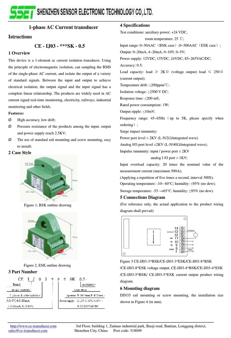
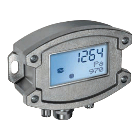
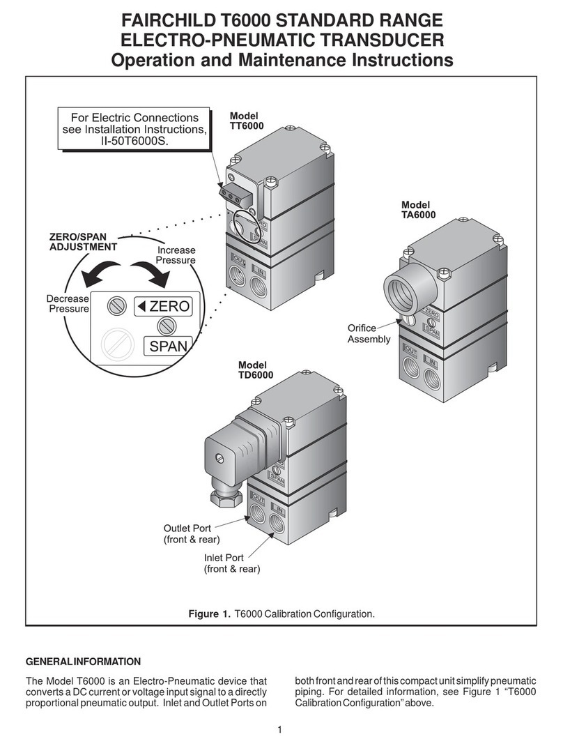
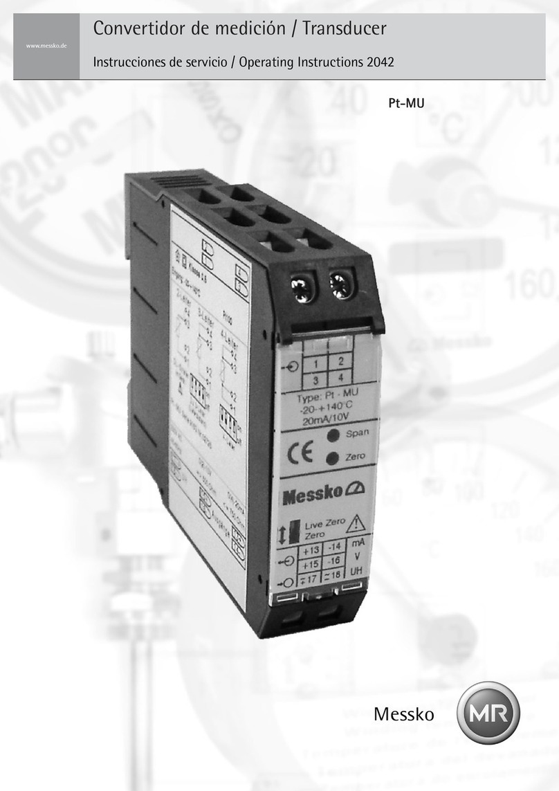
MESSKO Pt-MU User manual

BA2042/07/05 DE-EN
MESSKO® Pt-MU
MESSWERTUMFORMER
MEASURING TRANSDUCER
Betriebsanleitung/Operating Instructions

BA2042/0/05
2
Inhaltsverzeichnis/Contents
Für zukünftige Verwendung aufbewahren! Please keep this manual for future reference!
HINWEIS
Die in dieser Betriebsanleitung enthaltenen Angaben
können von dem gelieferten Gerät abweichen.
Änderungen bleiben vorbehalten.
NOTE
Data contained herein may differ in details from the
equipment delivered.
We reserve the right to make alterations without notice.
Inhaltsverzeichnis
1
1.1
1.2
1.3
2
3
4
Sicherheit.................................... 3
Sicherheitshinweise............................ 3
Bestimmungsgemäße Verwendung ............... 3
Hinweise für den Betrieb des Geräts.............. 3
Produktbeschreibung .......................... 4
Montage..................................... 5
Elektrischer Anschluss.......................... 5
4.1
4.2
4.3
4.4
4.5
2-Leiterschaltung ............................. 6
3-Leiterschaltung ............................. 6
4-Leiterschaltung ............................. 6
Gleichstromsignal ............................. 6
Gleichspannungssignal ......................... 7
5
6
Technische Daten ............................. 8
Anhang...................................... 9
Contents
1
1.1
1.2
1.3
2
3
4
Safety....................................... 3
Safety instructions ............................ 3
Specified application .......................... 3
Important notes on equipment operation ......... 3
Product specification .......................... 4
Electrical connection .......................... 5
4.1
4.2
4.3
4.4
4.5
2-wire configuration........................... 6
3-wire configuration........................... 6
4-wire configuration........................... 6
Direct current signal ........................... 6
Direct voltage signal........................... 7
5
6
Technical data ................................8
Appendix .................................... 9
Mounting .................................... 5

3
1 Sicherheit/Safety
1 Sicherheit
1.1 Sicherheitshinweise
Alle Personen, die mit der Montage, Inbetriebnahme,
Bedienung, Wartung und Instandhaltung des Geräts zu tun
haben, müssen
- fachlich ausreichend qualifiziert sein und
- diese Betriebsanleitung genau beachten.
Bei Fehlbedienung oder Missbrauch drohen Gefahren für
- Leib und Leben,
- das Gerät und andere Sachwerte des Betreibers und
- die effiziente Funktionsweise des Gerätes
In dieser Betriebsanleitung werden drei Arten von Sicher-
heitshinweisen verwendet, um wichtige Informationen
hervorzuheben.
1 Safety
1.1 Safety instructions
All personnel involved in installation, commissioning,
operation or maintenance of this equipment must:
- be suitably qualified and
- strictly observe these operating instructions.
Improper operation or misuse can lead to
- serious or fatal injury,
- damage to the equipment and other property of the user
- a reduction in the efficiency of the equipment.
Safety instructions in this manual are presented in three
different forms to emphasize important information.
1.2 Specified application
The measuring transducer Pt-MU isolates and convents a
Pt100-signal into a load-independent direct-current and
direct-voltage signal.
It is important to read and observe the limit values for
operation indicated on the nameplate and in the operating
instructions prior to commissioning the device.
Improper use and failure to follow these instructions for use
will render the warranty or guarantee null and void.
1.3 Important notes on equipment operation
The user is obliged to comply with the national health and
safety regulations.
1.2 Bestimmungsgemäße Verwendung
Der Messwertumformer Pt-MU dient zur Trennung und
Umformung eines Pt100-Eingangssignals in ein eingeprägtes
Gleichstrom- und Gleichspannungssignal.
Vor Inbetriebnahme des Geräts sind die auf dem Typenschild
und in der Betriebsanleitung angegebenen Grenzwerte in
der Anwendung zu beachten und unbedingt einzuhalten.
Eine nicht bestimmungsgemäße Nutzung sowie die
Nichtbeachtung dieser Anwendungshinweise haben den
Verlust der Gewährleistung bzw. Garantie zur Folge.
1.3 Hinweise für den Betrieb des Geräts
Die nationalen Unfallverhütungsvorschriften hat der
Anwender unbedingt einzuhalten.
CAUTION
This information indicates particular danger to the
equipment or other property of the user. Serious or fatal
injury cannot be excluded.
ACHTUNG
weist auf Gefahren für das Gerät oder andere Sachwerte
des Betreibers hin. Ferner können Gefahren für Leib und
Leben nicht ausgeschlossen werden.
HINWEIS
weist auf wichtige Informationen zu einer konkreten
Thematik hin.
WARNUNG
weist auf besondere Gefahren für Leib und Leben hin.
Ein Nichtbeachten dieser Hinweise kann zu schwersten
Verletzungen oder Tod führen.
NOTE
These notes give important information on a certain
issue.
WARNING
This information indicates particular danger to life and
health. Disregarding such a warning can lead to serious
or fatal injury.
BA2042/07/05

BA2042/0/05
4
2 Produktbeschreibung/Product specification
ACHTUNG
Betriebsanleitung beachten!
Das beschriebene Gerät darf ausschließlich durch
qualifizierte Elektrofachkräfte gemäß DIN EN 50110-1/-2
sowie IEC 60364 installiert werden.
- Prüfen Sie das Gerät vor Inbetriebnahme auf
Transportschäden.
- Bei Beschädigungen darf das Gerät nicht in Betrieb
genommen werden.
- Halten Sie bei der Verwendung des Gerätes die geltenden
Gesetze, Normen und Bestimmungen ein.
2 Product specification
The measuring transducer Pt-MU converts a Pt100 signal
into an apropriate direct current and a voltage signal.
It can be connected to the Pt100 resistor thermometer (acc.
to IEC 751), such as Messko´s ZT-F2.1 or combi well.
A constant measurement current flows via the resistance
thermometer and generate a voltage drop. This direct voltage
is linearized, amplified and galvanic isolated and transformed
at the output into an impressed direct current and in an
impressed direct voltage.
Both outputs are no-load proof and short-circuit proof.
Connecting the two outputs is not permissible.
A power supply is required.
Zero: e.g. 0-20 mA/0-10 V
Live Zero: e.g. 4-20 mA/2-10 V
For further processing, the output signal can be used for
downstream elements, e.g. a digital display, a moving coil
indicator, or a SCADA system.
The device is maintenance-free when used correctly.
CAUTION
Observe instructions!
The device described in these instructions shall only be
installed by a qualified electrician according to both
EN 50110-1/-2 and IEC 60364.
- Before startup, check the device for any damage that
may have occurred during shipping.
- The device shall not be put into operation in the event
of mechanical damage.
- Observe in the use of the device the applicable laws,
standards, and regulations.
2 Produktbeschreibung
Der Messwertumformer Pt-MU wandelt ein Pt100-Signal
in ein eingeprägtes Strom- und Spannungssignal um.
Er ist geeignet zum Anschluss an Pt100-Widerstandsther-
mometer (nach IEC 751), z.B. ZT-F2.1 oder Kombihülse.
Ein konstanter Messstrom fließt durch das Widerstands-
thermometer und erzeugt einen Spannungsabfall. Diese
Gleichspannung wird linearisiert, verstärkt und galvanisch
getrennt und am Ausgang in einen eingeprägten Gleich-
strom und in eine eingeprägte Gleichspannung umgeformt.
Beide Ausgänge sind leerlauf- und kurzschlussfest. Eine
Verbindung zwischen beiden Ausgängen ist unzulässig.
Eine Versorgungsspannung ist erforderlich.
Zero: z. B. 0-20 mA/0-10 V
Live Zero: z. B. 4-20 mA/2-10 V
Das Ausgangssignal kann in nachgeschalteten Elementen,
wie z. B. Digitalanzeige,Drehspulanzeige oder SCADA-
System weiterverwendet werden.
Das Gerät ist bei sachgemäßer Anwendung wartungsfrei.
Mit dem Zero-Schalter (siehe Bild 6) kann der Nullpunkt
des Ausgangssignals eingestellt werden:
The zero point of the output signal can be adapted by means
of the zero switch shown in Fig. 6:
Bild 1/Fig. 1

5
4
Montage/Mounting
Elektrische Anschlüsse/Electrical connections
4 Elektrischer Anschluss 4 Electrical connection
ACHTUNG
Der elektrische Anschluss darf ausschließlich von
qualifiziertem, ausgebildetem Personal, welches in die
entsprechenden Sicherheitsvorschriften des jeweiligen
Landes unterwiesen wurde, durchgeführt werden.
Geeignetes Elektrowerkzeug muss verwendet werden.
CAUTION
Electrical connection may only be carried out by quali-
fied, skilled personnel trained in the applicable health &
safety regulations of the relevant country.
It is imperative to use suitable electric tools.
WARNUNG
Schutz gegen gefährliche Körperströme.
Bei Anwendungen mit hohen Arbeitsspannungen auf aus-
reichend Abstand bzw. Isolation zu anderen Geräten und auf
Berührungsschutz achten. Gefährliche elektrische Spannung
kann zu elektrischem Schlag und Verbrennungen führen.
Schalten Sie immer alle verwendeten Spannungsversorgungen
für das Gerät ab, bevor Sie das Gerät montieren, installieren,
Störungen beheben oder Wartungsarbeiten vornehmen.
WARNING
Protection against electric shock.
For applications with high working voltages, take measures
to prevent accidental contact and make sure that there is
sufficient distance or insulation between adjacent devices.
High voltage can cause electric shock or burns.
Switch off all power to the device prior to performing any
installation, repair, or maintenance work.
Nach Abheben der Klarsichtscheibe kann mit einem
Schraubendreher (2,5 mm) am Potentiometer "SPAN" der
Endwert und am Potentiometer "ZERO" der Nullpunkt (nur
bei 2-Leiterschaltung) justiert werden.
After open the clear cover it is possible to adjust with a
screwdriver with a width of 2.5 mm on the potentiometer
which is named "SPAN" the final value and with the
potentiometer which is named "ZERO" the zero-point (only
at 2-wire circuit).
BA2042/07/05
Bei Umgebungstemperaturen > 45 °C wird ein Abstand von
10 mm empfohlen. Der Montageort muss vibrationsfrei sein
und darf 55 °C Umgebungstemperatur im Betrieb nicht
überschreiten.
Installieren Sie das Gerät nur in trockenen Räumen. Die
Montage des Gerätes darf nicht auf oder an leicht
entzündlichen Materialien erfolgen.
Die Montage erfolgt über die Schnappbefestigung auf der
Rückseite des Gerätes auf einer Normschiene 35 mm (TH35
nach DIN EN 60715). Die Geräte sind für dicht an dicht
Montage geeignet.
Only install this device in dry rooms. Do not install the devices
on or in the vicinity of easily flammable materials.
The measuring transducer is mounted to a standardized 35 mm
rail (TH35 acc. to DIN EN 60715)using the snap-on fixing
located on the rear face. The measuring transducers are
perfectly suited for mounting right next to each other.
However, in the pre-sence of ambient temperatures > 45 °C a
distance of 10 mm between the devices is recommended. The
mounting location should be non-vibrating and the ambient
temperature must not exceed 55°C while operation.
ACHTUNG
Die in dieser Betriebsanleitung vorgeschriebenen
Betriebs- und Montagebedingungen müssen strikt
eingehalten werden.
CAUTION
The operating and mounting conditions demanded by
this operating manual must be strictly complied with.
3 Montage 3 Mounting
3
ACHTUNG
Schutzmaßnahmen gegen elektrostatische Entladungen
(ESD) sicherstellen.
CAUTION
Be sure to take protective measures against electrostatic
discharge (ESD).

6
4 Elektrische Anschlüsse/Electrical connections
4.1 2-Leiterschaltung
Der Leitungswiderstand zwischen Pt100 und dem Pt-MU muss
weniger als 10 Ωbetragen. Der Abgleich des Leitungswi-
derstandes erfolgt mit dem „ZERO“ Potentiometer unter der
Sichtscheibe des Geräts. Der Anschluss des Pt100 erfolgt an
den Klemmen 1 und 3, die Klemmen 3 und 4 müssen gebrückt
werden.
4.2 3-Leiterschaltung
Hier ist kein Abgleich der Leitungswiderstände (< 100 Ω)
erforderlich. Der Anschluss des Pt100 erfolgt an den Klemmen
1 und 3, die Ausgleichsleitung wird an der Klemme 4 ange-
schlossen.
4.3 4-Leiterschaltung
Beim Anschluss des Pt100 mit 4-Leitertechnik muss der front-
seitige Schalter (siehe Bild 6) umgestellt werden. Ein
Abgleich der Leitungswiderstände (< 100 Ω) ist nicht
erforderlich. Der Anschluss des Pt100 erfolgt an den
Klemmen 2 und 3, die Ausgleichsleitungen werden an den
Klemmen 1 und 4 angeschlossen.
4.1 2-wire circuit
The line resistance between Pt100 and the Pt-MU must be
less than 10 Ω. Calibration of the line resistance is done with
the „ZERO“ potentiometer under the viewing window of the
device. The Pt100 is connected to terminals 1 and 3. Terminals
3 and 4 must be jumpered.
4.2 3-wire circuit
Calibration of the line resistances (< 100 Ω) is not necessary
here. The Pt100 is connected to terminals 1 and 3. The com-
pensation line is connected to terminal 4
4.3 4-wire circuit
When the Pt100 is connected for 4 wire application, the
front switch (refer to Fig. 6) must be changed over.
Calibration of the line resistances (< 100 Ω) is not
necessary. The Pt100 is connected to terminals 2 and 3. The
compensation lines are connected to terminals 1 and 4.
4.4 Direct current signal
When several evaluation devices (e.g., switching and
regulating devices, measuring devices, writers and so on) are
connected to the current output, these must be circuited in
series to the transducer (make sure that polarity is correct).
The maximum load of 500 Ω(including the feeder line) may
not be exceeded. Connection is made to terminals 13 and 14.
2-Leitertechnik/2-wire configuration
Bild 2/Fig. 2
3-Leitertechnik/3-wire configuration
Bild 3/Fig. 3
4-Leitertechnik/4-wire configuration
Bild 4/Fig. 4
4.4 Gleichstromsignal
Werden mehrere Auswertegeräte wie Schalt- und Regel-
geräte, Messgeräte, Schreiber u.s.w. mit Stromeingang
angeschlossen, so müssen diese in Reihe mit dem Ausgang
des Messumformers geschaltet werden (Polarität beachten!).
Die maximale Bürde von 500 Ω(einschließlich der Zuleitung)
darf nicht überschritten werden. Der Anschluss erfolgt an
den Klemmen 13 und 14.
BA2042/07/05

ACHTUNG
Die Angaben in dieser Betriebsanleitung sind für
Standardgeräte gültig. Bei Sonderausführungen sind die
Angaben des Typenschildes und der Bestellung zu
beachten.
CAUTION
The specifications given in this operating instructions are
for standard products. For special designs you have to
take care about the notes given in the order and on the
nameplate.
4.5 Gleichspannungssignal
Werden mehrere Auswertegeräte wie Schalt- u. Regelge-
räte, Messgeräte, Schreiber u.s.w. mit Spannungseingang
angeschlossen, so müssen diese parallel zum Ausgang des
Messumformers geschaltet werden (Polarität beachten). Der
Anschluss erfolgt an den Klemmen 15 und 16. Der Ausgang
darf mit max. 10 mA belastet werden.
Bei gleichzeitiger Verwendung beider Ausgänge darf der
Spannungsausgang mit max. 1 mA belastet werden. Eine
Verbindung zwischen beiden Ausgängen ist unzulässig.
4.5 Direct voltage signal
When several evaluation devices (e.g., switching and
regulating devices, measuring devices, writers and so on) are
connected to the voltage output, these must be circuited
parallel to the transducer (make sure that polarity is correct).
Connection is made to terminals 15 and 16. The maximum
load of the output is 10 mA.
When both outputs are used simultaneously, the maximum
load of the voltage output is 1mA. Connection between the
two outputs is not permitted.
Bild 5/Fig. 5
4 Elektrische Anschlüsse/Electrical connections
7
BA2042/07/05

BA2042/0/05
8
5 Technische Daten/Technical Data
5 Technische Daten
Eingang
Eingangsgröße:
Messbereich:
2-Leitertechnik:
3-Leitertechnik:
4-Leitertechnik:
Hilfsspannung:
Pt100 nach DIN EN 60751
0 bis160 °C oder -20 bis 140 °C
Leitungswiderstand < 10 Ω,
Abgleich durch Potentiometer
Leitungswiderstand < 100 Ω,
kein Abgleich erforderlich
Leitungswiderstand < 100 Ω,
kein Abgleich erforderlich
230 V AC ±20%, 45-65 Hz, 2,5 VA;
alternativ 110 V AC auf Anfrage
Ausgang
Ausgangsgröße: Eingeprägter Gleichstrom und einge-
prägte Gleichspannung entsprechend
Stromausgang:
Typenschild (z.B. 4–20 mA und 2–10 V)
Bürde max. 500 Ω
Spannungsausgang: Belastung max. 10 mA;bei Verwendung
beider Ausgänge: max. 1 mA
Übertragungsverhalten
Genauigkeit:
Temperaturbereich: -15 bis +55°C
5 Technical Data
Input
Input size:
Meas. range:
Pt100 as per EN 60751
0 to 160 °C or -20 to 140 °C
2-wire technique: Line resistance < 10 Ω,
calibration with potentiometer
3-wire technique: Line resistance < 100 Ω,
no calibration required
4-wire technique: Line resistance < 100 Ω,
Auxiliary voltage:
no calibration required
230 V AC ±20%, 45 to 65 Hz, 2.5 V A;
alternative 110 V AC on request
Output
Output size: Proportional direct current and pro-
portional direct voltage, as per name-
plate (e.g., 4 to 20 mA and 2 to 10 V)
Current output:
Voltage output:
Load of max. 500 Ω
Max. load of 10 mA;when both
outputs are used: max. load of 1 mA
Dynamic system behavior
Accuracy:
Temperature range: -15 to +55°C
±0,5 % vom Endwert bei Umgebungs-
temperaturen von 20°C bis 30°C
Temperaturdrift: < 0,1 % / 10 K
±0,5 % of the final value in ambient
temperatures between 20°C and 30°C
Temperature drift: < 0.1 % / 10 K
Bürdeeinfluss: Nein
Restwelligkeit:
Einstellzeit:
Schutzart:
Prüfspannung:
EMV:
Load influence: No
Residual ripple:
Settling time:
Protection rating:
Test voltage:
EMC:
Electrical safety:
Fuse:
Terminals:
Ambient conditions:
Weight:
< 30 mVSS
< 300 msec
Housing: IP30, terminals: IP20,
in acc. with EN 60529
4 kV, 50 Hz input against output against
power supply
EN 61326
EN 61010-1, housing insulated, protection
class II, for working voltages up to 300 V
(phase to neutral)
pollution degree 2
measuring category CAT III
The device is equipped with short-circuit
proof transformers, no overcurrent
protective device for the transducer is
required.
Screw terminals max. 4 mm²,
tightening torque 0.8 Nm
Stationary application, weather protected;
rel. air humidity 5 to 95 %,
no condensation; altitude up to 2000 m;
water, rain, snow or hail excluded
Approx. 170 g
Elektrische Sicherheit:
Absicherung:
Anschlussklemmen:
Umgebungs-
bedingungen:
Gewicht:
< 30 mVSS
< 300 ms
Gehäuse: IP30, Klemmen: IP20
nach DIN EN 60529
4kV 50 Hz,Eingang gegen Ausgang gegen
Versorgungsspannung
DIN EN 61326
DIN EN 61010-1, Gehäuse schutzisoliert,
Schutzklasse II, bei Arbeitsspannungen bis
300 V (Netz zu Neutralleiter)
Verschmutzungsgrad 2
Messkategorie CAT III
Die Geräte sind mit kurzschlussfesten
Transformatoren ausgestattet, auf eine
Überstrom-Schutzeinrichtung für den
Umformer selbst kann verzichtet werden.
Schraubanschluss max. 4 mm²,
Anzugsmoment 0,8 Nm
Ortsfester Einsatz, wettergeschützt;
rel. Luftfeuchte 50–95 %, keine Betauung;
Höhe bis 2000 m; kein Wasser, Regen,
Schnee oder Hagel
ca. 170 g

9
6 Anhang/Appendix
6 Anhang/Appendix
ACHTUNG
Änderungen an den DIL-Schaltern nur in spannungsfreiem
Zustand vornehmen.
CAUTION
Changes to the DIL switches may only be made in a
de-energized state.
Bild 6/Fig. 6
BA2042/07/05


Messko GmbH
Gewerbegebiet An den Drei Hasen
Messko-Platz 1, 61440 Oberursel, Germany
Phone: +49 6171 6398-0
Fax: +49 6171 6398-98
Email: [email protected]
www.messko.com
Bitte beachten: Die in allen unseren Publikationen enthaltenen
Angaben können in Details von dem gelieferten Gerät abweichen.
Änderungen bleiben vorbehalten.
Für zukünftige Verwendung aufbewahren!
Important note: The information contained in all of our
publications may differ in detail from the actual equipment
delivered. We reserve the right to make alterations without notice.
Please keep this manual on hand for future reference!
BA2042/07/05 DE-EN – MESSKO® Pt-MU –
MS99032706 – 06/16 ©Messko GmbH 2016
Other manuals for Pt-MU
2
Table of contents
Other MESSKO Transducer manuals
Popular Transducer manuals by other brands

HBM
HBM Z6R Series operating manual

HBM
HBM C18 Mounting instructions

S+S Regeltechnik
S+S Regeltechnik PREMASREG 7100 VA ID Series Operating Instructions, Mounting & Installation

UIS
UIS WDT-110 user manual

Setra Systems
Setra Systems 567 installation guide

Garmin
Garmin LIVESCOPE PLUS installation instructions

MTS Systems
MTS Systems Temposonics II LDT Installation instructions manual

Fairchild
Fairchild T7800 Series Installation, operation and maintanance manual

Furuno
Furuno 82B-35R Operator's manual

LEYBOLD
LEYBOLD DI2000 operating instructions

HBM
HBM AD104-R2 operating instructions

WT sensor
WT sensor PCMPT01 Series quick start guide