6Rubber washer
7Anti{otation bolt
8Transducer stem
IAnti-rotation bolt cap
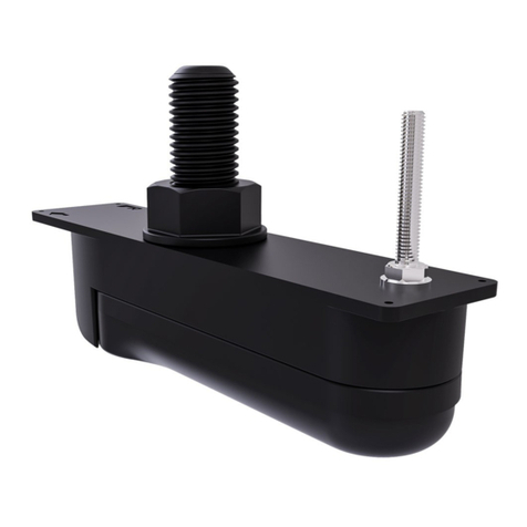
10 Transducer
't'l lvlarine grade sealant (non-acetate based)
12 Direction of vessel's bow
Uslng the location guidelines provided, ensure
you have selected an appropriate location for the
transduce( (See Location requirernents.)
Check the labels on the bronze face ofthe transducer
to confirm that you are using the correct type of
transducer (element angle; port or starboard) for the
mounting location you have chosen.
Fix the transducer mounting template to the selected
location using masking or self-adhesive tape,
ensuring that the arrow on the template is pointed
towards the vessel's bow.
4. Drill a pilot hole for the transducer stem hole.
5. Drill the stem-hole out using a suitable size hole
cutteI
6. Using a half round file and / or sandpaper, ensure
there are no rough edges or burrs around the stem
hole.
7 Guide the transducer cable up through the hole in
the vessel's hull while supporting the transducer
from beneath.
8. From inside the vessel, feed the transducer cable
through the rubber washel
9. Guide the transducer stem up through the hole in
the vessel's hull, while supporting the transducer
from beneath.
10. With the transducer held in place, check that the
anti-rotation bolt hole lines up correctly with the
mounting template.
11. Drill a pilot hole for the anti-rotation bolt hole.
12. Drill the hole for the anti-rotation bolt using a suitable
size drill bit.
13. Lower the transducer away from the hull (while
keeping the cable threaded through the hull), and
remove the mounling template; ensure that the
transducer is still supported from beneath.
'14. Carefully remove all labels from the bronze face of
the transducer.
15. Wipe all surfaces, both outside and inside the hull,
with an appropriate cleaning agent (for example,
isopropyl alcohol), and ensure they are dry, clean
and free from debris.
16. Apply a thick bead of marine-grade sealant:
i. all around the base ofthe transducer stem, where
it will meet the hull.
ii. all around the threaded section of the
stem, ensuring that the sealant will protrude
approximately 6 mm abrove the final tightened
hull nut.
iii. all around the stem hole, on the exterior of the
hull.
iv all around the anti-rotation bolt hole, on the
exterior of the hull.
'17 Apply marine-grade sealant all over the top, bronze
face of the transducet where it will meet the hull.
18. Guide the transducer stem up throuqh the hole in
the vessel's hull, while supporting the transducer
from beneath.
19. Fit the anti-rotation bolt by sliding it up through the
transducer housing, ensuring that the bolt head is
properly seated within the transducer
20.Apply a thick bead of marine-grade sealant:
i. all around the stem hole, on the interior ofthe hull.
ii. all around the anti-rotation bolt hole, on the
interior of the hull.
21. Slide the rubber washer down the transducer cable,
and over the threaded section of the transducer
stem; ensure that the washer is sitting on the sealant.
22. Ensuring the cable protector is fitted to the hull nut,
feed the transducer cable through the nut, resting
the nut on top of the threaded stem-tube.
23. Remove the Cable protector by pulling the 2 tabs
away from the back of the Hull nut.
24.Apply a thick bead of marine grade sealant to the
bottom face of the Hull nut.
25.Screw the hull nut onto the threaded stem-tube and
tighten by hand.
26.Fully tighten the hull nut using a sultable sized
wrench (spanner).
ln order to prevent leaks and transducer movement,
ensure that the nut is adequately tightened. You
shou/d see the sealant protruding from the edges of
all applied surfaces.
lmportant Do NOT overtighten. Overtightening can
cause damage to the hull which may result in water
leakinq into the vessel.
o
"rA
)( ffi D)
,V
27 From inside the vessel, slide the small bronze washer
over the anti-rotation bolt.
28.Screw the anti-rotation bolt nut onto the bolt and
tighten by hand.
29. Fully tighten the anti-rotatlon bolt nut using a suitable
sized wrench (spanner).
lmportant Do NOT overtighten. Overtightening can
cause damage to the hull which may result in water
leaking into the vessel.
30.Apply a small amount of marine grade sealant to the
inside of the anti-rotation bolt cap.
31. Fit the anti-rotation bolt cap by pressing it firmly into
the hole in the bottom face of the transducer.
34. Once the vessel has been put back in the water
check for leaks around the transducer immediately.
Important Do NOT leave your vessel in the water
unchecked for more than a few hours after first
installing the transducel Very small leaks may not
be immediately obvious, and considerable bilge
water could accumulate over the course of a day,
or overnight.
35. Check for leaks at regular interuals after installation
until you are satisfied that there are no leaks.
36. Ensure checking for leaks around the transducer is
added to your routine vessel maintenance schedule.
Cable routing
Cabie routing requirements for the transducer cable.
lmportant To avoid intederence, the cable must be
routed as far away from VHF radio antenna cables
as possible.
Check that the cable is long enough to reach the
equipment it will be connected to. lf you are installing
split-pair transducers, you must use a Y-cable
(A8O478) along with an extension cable to connect
the transducers to your multifunction display. The
following optional extension cables are available:
- Realvision'" transducer extension cable 3 m (9.8 ft)
(part number A80475)
- Realvision'. transducer extension cable 5 m (16.4
ft) (part number 480476)
- Realvision'" transducer extension cable I m (26.2
ft) (part number 480477)
Use grommets in any pass through holes to prevent
damage to the transducer cable.
Secure the cable at regular interuals using cable clips
(not supplied).
Any excess cable should be coiled up at a convenient
location.
Attaching the connector locking
collar
The supplied cable is provided with a separate locking
collar assembly, ensuring that the cable connection is
secure_
This procedure describes how to attach the locking
collar to the cable connectol The locking collar parts
are supplied in a separate bag, in the package with your
product.
lmportant: Ensure that you route the cable all the
way to its destination before attaching the locking
collaI
1. Slide the locking collar over the end of the connector,
then push it towards the cable-end of the connecto[
lmportant Ensure that the lugs on the locking collar
(labelled A in the illustration), are closest to the
plug-end of the connector
Ensure that the anti-rotation bolt cap (1), is oriented
correctly, with the embossed "BOW" arrow pointing
towards the temperature sensor in the base of the
transducer (2).
32.To prevent aeration around the transducer, remove
any excess sealant on the outside of the hull.
33. Ensure that the sealant has fully cured before putting
the vessel back in the water
Refer to the sealant manufacturer's instructions for
curing times.
as.-\)@
@*m-'
6 _3f\
2. Slide the split-ring over the end of the connector,
then push it towards the cable-end of the connector
