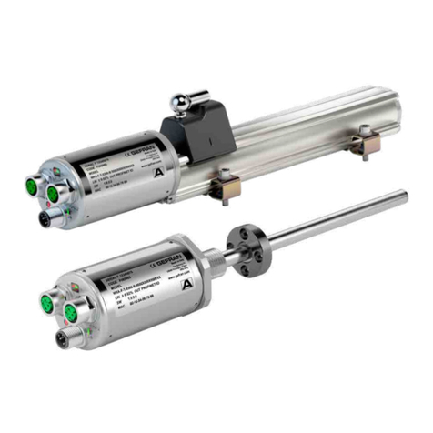
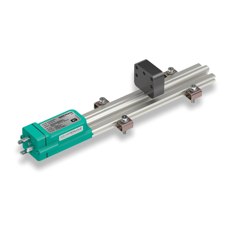
gefran MK4 Series User manual

185190A_MAN_Installazione_MK4-IK4/SK4_11-2012_ENG
MK4 and IK4/SK4 Series
Installation Manual
Code 85190A Edition 11-2012
G
eneral
P
recautions
Pag. 2
MK4 Series C
orrect use of installation brackets
Pag. 2
MK4 Series C
orrect use of the
PCUR034
floating cursor
Pag. 3
IK4/SK4 Series M
ounting inside acylinder
Pag. 4
I
nstructions for electrical installation of magnetostrictive transducers
Pag. 5
D
etails on models with ssi output
(MK4-S and IK4-S) Pag. 5
D
ata format
Pag. 5
E
rror messages
Pag. 6
O
versampling
option
Pag. 6
D
etails on models with
CANOPEN
output
(MK4-C and IK4-C) Pag. 7
D
iagnostics of models with
leds
Pag. 7
CONTENTS

285190A_MAN_Installazione_MK4-IK4/SK4_11-2012_ENG
GENERAL PRECAUTIONS
•Thetransducermustbeinstalledawayfromsourcesofmagneticfields,bothstaticand50Hz(electricmotors,solenoids,
etc.).
•Thetransducerconnectioncablemustbewiredseparatelyfrompowercablesand/orsolenoidcontrols,drives,orremote
switches.
•Thelineusedforpowersupplymustbededicatedtothetransducersormustbedrawndirectlyfromthepowerterminals
andasnearaspossible.
•WhenchoosingacursorfortheMK4profilemagnetostrictivetransducer,rememberthatthetransducer’scursorisa
magnet.
Therefore,ifthere are iron filings or small magnetic metal fragments in proximity ofthetransducer, avoid the use of
slidingcursors,astherewouldbeariskofmaterialaccumulationonthecursor,creatingproblemsforsliding.
Useafloatingcursorinstead.
MK4 SERIES – CORRECT USE OF INSTALLATION BRACKETS
UsePKIT09xbrackets(tobeorderedseparately)tocorrectlyinstalltheMK4magnetostrictivetransducer.
Choosethe best model based on the material, on the attachmentholesinteraxis and on the dimension of the screws
includedinthepackage.Eachpackagehastwobrackets.
Werecommendtoinstallonebracketevery250-300mm.
Alwaysusetheisolatingbushessuppliedinthepackagetoensurethecorrecttransducerisolation.
Topreventdamagestotheisolatingbushesandtothebrackets,tightenthefasteningscrewswithamaximumtorqueof
1.1Nm.
Brackets (2bracketsforeverykit)
Steelbracket,interaxis42.5mm
P K I T
Steelbracket,interaxis50mm
090
091
Bracketscode Interaxis(i) Screw(V) Dimension(A)
PKIT090/093 42.5 M4 56
PKIT091/092 50 M5 63.5
Stainlesssteelbracket,interaxis42.5mm 093
Stainlesssteelbracket,interaxis50mm 092

385190A_MAN_Installazione_MK4-IK4/SK4_11-2012_ENG
MK4 SERIES – CORRECT USE OF THE PCUR034 FLOATING CURSOR
Understandardconditions(Fig.1),thePCUR034cursormustbeinstalledonasupportmadeofnon-magneticmaterial
(suchasbrass,aluminium,orAISI316stainlesssteel).
Theinstallationkit,consistingoftwoscrews,twonuts,andtwowashers(allmadeofbrass),isincludedinthepackage.
Thecursor(Fig.2)mustbeinstalledwithmaximumattentiontohorizontalalignmentwiththetransduceraxis(maximum
toleranceis±2mm),aswellastothedistancefromthetransducersurfacefrom2to7mm(0to7mmforMK4-Sver-
sionwithdigitalSSIinterface).
Ifthereisnoalternativetoamagneticsup-
port,it’snecessarytopreventthesupport
fromchangingthemagneticfieldgenerated
bythecursor,becausethiscouldcausepro-
blemswiththecorrectmeasurementofthe
cursorposition.
Forthisreason,anon-magneticspacer
mustbeaddedbetweenthecursorandthe
magneticsupport(Fig.3-Sol.1).
Therecommendedspacerthicknessis15mm.
Iftheapplicationdoesnotpermittheinstal-
lationofanon-magneticspacer,it’spossible
toinstallthecursordirectlyonthemagnetic
support,beingcarefulnottoletthesupport
makedirectcontactwiththepartofthecursor
containingthemagnet(Fig.3-Sol.2).
Iftheapplicationrequiresinstal-
lationofmultiplecursors(twoor
more),thecursorsmustbemini-
mum75mmapart(Fig.4).
Rememberthatinordertoensu-
reprecisemeasurement,each
magnetmustbeinstalledatthe
samedistancefromthetransdu-
cersurface.
Inaddition,allcursorsmustbe
keptatthesameworkingtempe-
rature.
Fig.1 Fig.2
Totallength
Totalstroke
Support
Cursor
Screws
96 58
max±2mm
2...7mm
Fig.4
min75mm.
Fig.3
Non-magnetic
Support
Magnetic
Support
Support
magnetic
Non-magnetic
spacer
Cursor Cursor Cursor
Screws Screws Screws
Sol.1 Sol.2
Max
12mm

485190A_MAN_Installazione_MK4-IK4/SK4_11-2012_ENG
Forthecorrectinstallationofrod-typemagnetostrictivetransducersinhydrauliccylinders,rememberthatthecylinderhead,
mustbemadeofnon-magneticmaterialwherethethreadedholewillbedrilledtoinstallthetransducer.
Ifnot,theresidualmagnetisationcausedbydrillingthethreadedholemustbelessthan4Gauss.
Rod-typemagnetostrictivetransducersareavailablewithtwotypesofthreads:M18x1.5or3/4”-16UNF.
Refertothedrawingsinfigures5and6forthedimensionsandtolerancestoberespectedwhendrillingthethreadedholes
andtherelatedsealingsurfaces.Thesealingsurfacemustbefreeofspiralorlongitudinalscratches.
•Ro1,6µmforO-ringswithNON-pulsingpressure
•Ro0,8µmforO-ringswithpulsingpressure
Rod-typemagnetostrictivetransducersarealwayssuppliedwithanO-ring.IfyouneedtoreplacethesuppliedO-ring,see
theO-ringsshowninfigures6and7.
SERIE IK4/SK4 - INSTALLAZIONE IN INTERNO CILINDRO
B
Inactive
zone
Non-magneticspacer
Floatingmagnet
ø 10
ø12.7
C.E.
A
Inactive
zone
Non-magnetichead
Fig.5
B A
IK4-S/C 47,5 63,5
IK4-A0...1000 47,5 55
IK4-A1250...4000 47,5 60
SK4 27,5 50
Fig.6
Version with thread M18x1,5
SuggestedO-Ring:
PARKER 6-34915,4x2,1
Material Viton90°Shore-A
Mixes PARKERN552-90
Version with thread 3/4”-16UNF
SuggestedO-Ring:
PARKER 3-90816,36x2,21
Material Viton90°Shore-A
Mixes PARKERN552-90
Fig.7

585190A_MAN_Installazione_MK4-IK4/SK4_11-2012_ENG
Topreventalterationsofthemagneticfieldgeneratedbythecursorand,therefore,incorrectmeasurementsbythe
transducer,thecursormustbeinstalledbyplacinganon-magneticspacer(madeofbrass,aluminium,stainlesssteelor
plastic)betweenthepistonsurfaceandthecursor.
Alwaysusefasteningaccessories(screws,washers,etc.)suppliedwiththecursor.Whennecessary,alwaysusenon-
magneticaccessories.
Remembertopositionthecursorinsuchawayastoallowthecorrectmeasurementwithintheelectricalstrokeofthe
magnetostrictivetransducer,preventingthecylinderstrokefrombringingthecursorintoinactivezonesofthetransducer.
INSTRUCTIONS FOR ELECTRICAL INSTALLATION OF MAGNETOSTRICTIVE TRANSDUCERS
Themagnetostrictivetransducersconformtothefollowingdirectives:
-ElectromagneticCompatibilityEMC2004/108/CE
-RoHS2002/95/CE
Foracorrectelectricalinstallationofthetransducers,refertothe“ManualforElectricalInstallationofMagnetostrictives.”
Themanualandcertificatesofconformitycanbedownloadedfromthewebsitewww.gefran.com.
DETAILS ON MODELS WITH SSI OUTPUT (MK4-S and IK4-S)
ThediagramshowstheoperationofasensorwithSSI
SynchronousSerialInterface.
Thepositionofthemagnetonthesensorisdefinedbythe
signalprovidedbythesensorusingthemagnetostrictive
technology.
ThedisplacementsignalissuppliedinbinaryorinGray
Code(24-25bit)andtransmittedtothecontrollerbymean
oftheSSIinterface.
Therefreshratecanbeupto1000measurements/second
(dependingonthetransducer’sstroke).
Theoutputisabsolute,meaningthatthedatarelatedto
themagnetpositionareimmediatelyavailablewhenthe
systemisturnedonagain.
BLOCK DIAGRAM
SSIInterface
DataShiftRegister
Parallel/Serial
BinaryorGrayCode
16,21,24or25bit
Positiondata
Shifttime=
Magnet
position
Start Stop
Time=Position
Fig.8
DATA FORMAT
Clocksequence
tmmin=16mSec,regardlessofclockfrequency
BAUD RATE FOR DATA TRANSMISSION (basedoncablelength)
Cable length <3m <50m <100m <200m <400m
Baud Rate 1Mbaud 400kbaud 300kbaud 200kbaud 100kbaud
Maxfrequency:1MHz
Minfrequency:50kHz
Fig.9

685190A_MAN_Installazione_MK4-IK4/SK4_11-2012_ENG
ERROR MESSAGES
TheSSIoutputgoesto0iftheechoisabsent(magnetoutofmeasurementrangeorinternaldeviceerror).
OVERSAMPLING OPTION
Thepositionofthemagnetonthesensorisdefinedbythemagnetostrictivetechnology.Internalpositionsamplingcanvary
from2kHzto500Hzdependingonthestroke.
ThedisplacementsignalissuppliedinbinaryorGraycodeandtransmittedtothecontrollerviaSSI.
Normally,whendataareavailable,theyaretransmittedtotheSSIshiftregister,wheretheyareavailabletothecontroller.
Therefore,theshiftregisterrefreshrateisequaltotheinternalinterrogationrate.
Intheversionwith“oversampling,”thetransducercontrolelectronicsissynchronisedwiththeSSIclocktrainsandprovides
anoutputbeforeeachinterrogation.
Thesupplieddataarecalculatedviaafirst-orderinterpolationandareequalto:
Out=M+V*T
M=lastinternalmeasurement
V=magnetspeed
T=timeelapsedsincelastmeasurement
Thedataissuppliedtotheshiftregi-
sterconsideringpossibleJitterinthe
controllerinterrogationtime(40mSec
iscurrentlyconsidered).
LowerJitterlevelsensurebetterinter-
polationresults(seeFigure10).
Tomaintainsynchronismbetween
SSIclockandshiftregisterrefresh,
theinterrogationratecanvaryfroma
maximumof5.5KHztoaminimumof
125Hz.
Typicalvalueconsidered=4KHz.
Securitytime=40µS+10µS
MAX ERROR IN CASE OF
JITTER IN SAMPLING TIME
CASE 1:Decreasingofsamplingtime
from270to230
CASE 2:Increasingofsamplingtime
from230to270
NORMAL OPERATION
InternalMeasure
DataonOut
Securitytime=50µS(compensated)
250µSsamplingtime
270µSsamplingtime
230µSsamplingtime
DataReady SSISampleTime
10µS
90µS
270µSsamplingtime
230µSsamplingtime
Thesystemdoesn’tlessthesample
Theerrorinpositionis=V*40µSes
Fig.10
Securitytime=50µS(compensated)

785190A_MAN_Installazione_MK4-IK4/SK4_11-2012_ENG
DETAILS ON MODELS WITH CANOPEN OUTPUT (MK4-C and IK4-C)
TheseriesofmagnetostrictivetransducerswithCANopenoutputintegratesamicroprocessortoprocessmeasurementand
communicationwiththeCANfieldbusbyusingtheCANopenDS-301protocolandDeviceProfileDS-406.
ByconnectingmultipletransducersinaCANopennetwork,it’spossibletochoosebetweenmodelswithoneconnectoror
withtwoconnectors.
Whenusingatransducerwithsingleconnector,theconnectionmustbeintheformof“T”connections,asshowninFig.11.
Inordertoavoidtheuseof“T”connections,it’spossibletooptforthe2-connectorsmodel(availablewiththeIK4-Cseries)
tomakeaconnectionasshowninFig.12.
Fig.11 Fig.12
IftheCANopennetworkterminateswithatransducer,thattransducermustcontainaterminationresistor.
Theterminationresistorintegratedinthetransducerisanoptionthatcanbeorderedbyspecifyingitintheordercodefor
thechosenmodel(see“Ordercode”onthedatasheet).
EachdeviceconnectedintheCANopennetworkmusthaveauniquenodenumberthatidentifiesit.
Eachmagnetostrictivetransducerisfactoryprogrammedwithastandardnodenumberof“127”.
AfewchangestothesettingsoftransducerswithCANopenoutput(suchasnodenumber,baudrate,etc.)canbeperfor-
medbyconnectingthemtoaCANmasterandprogrammingtheparametersintheproperway.
Thecommunicationprotocol,thelist,andthedescriptionofthetransducer’sparametersareshowninthemanual,thatcan
bedownloadedfromthewebsitewww.gefran.com.
DIAGNOSTICS OF MODELS WITH LEDS
SomemagnetostrictivetransducershaveLEDstodisplaysomesimplediagnosticfunctions.
Basedonthemodel,thestateoftheLEDsmayhavedifferentmeanings,asshowninthefollowingtable.
IK4-A/SK4-A Series (analogue output) Serie IK4-A/SK4-A (uscita analogica
Red LED Meaning
on Transducerpoweredandworkingcorrectly
flashing Echoabsent(magnetoutofmeasurementrangeorinternaldeviceerror)
off Transducernotpowered
IK4-S Series (SSI output) and IK4-C Series (CANopen output)
Red LED Meaning
on Echoabsent(magnetoutofmeasurementrangeorinternaldeviceerror)
off Transducerworkingcorrectly

885190A_MAN_Installazione_MK4-IK4/SK4_11-2012_ENG
GEFRAN spa
viaSebina,74
25050PROVAGLIOD’ISEO(BS)-ITALIA
tel.0309888.1-fax.0309839063
Internet:http://www.gefran.com
This manual suits for next models
2
Table of contents
Other gefran Transducer manuals
Popular Transducer manuals by other brands

S+S Regeltechnik
S+S Regeltechnik PREMASGARD 711 Series Operating Instructions, Mounting & Installation

S+S Regeltechnik
S+S Regeltechnik THERMSGARD RGTM2 Series Operating Instructions, Mounting & Installation

Hummingbird
Hummingbird XTH 9 20 P manual

Balluff
Balluff BTL6-V5 V-M-PF-S115 Series Condensed guide

controlair
controlair 500-BD Installation, operation and maintenance instructions

Pribusin
Pribusin IUC-7X-WTX instruction manual