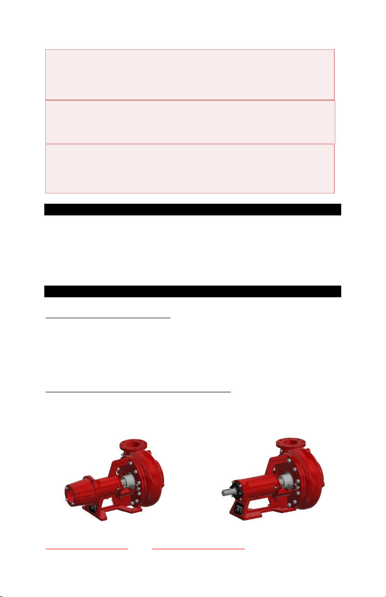
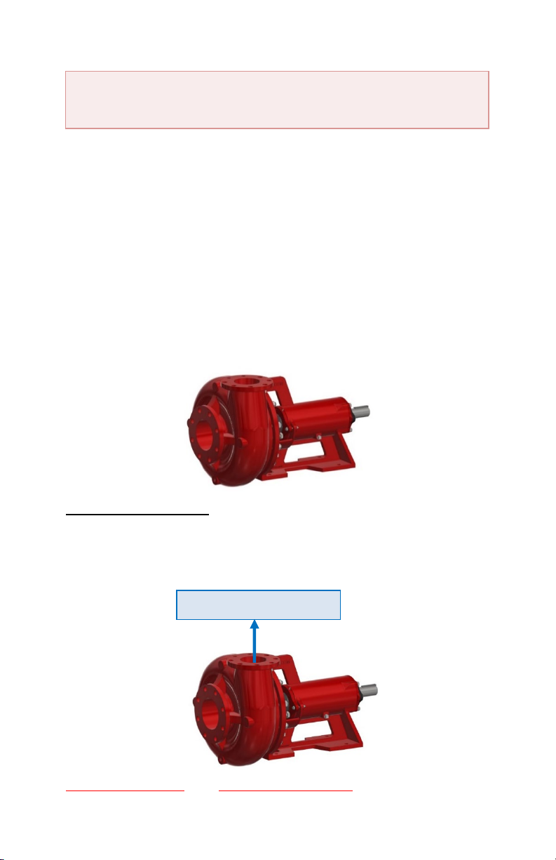
Mud Puppy 250 Installation, Operation & Maintenance Manual
3
ABNORMALLY HIGH TEMPERATURES 28
GREASE APPEARANCE 28
NOISE 28
BEARING DISCOLORATION 28
RETAINER FAILURE 28
DIRTY LUBRICATION 29
TOO MUCH LUBRICANT 29
WRONG KIND OF LUBRICANT 29
MISCELLANEOUS INFORMATION 29
OPERATING LIMITS OF RIG CENTRIFUGAL PUMPS 29
SUCTION LINE VELOCITY 29
NET POSITIVE SUCTION HEAD (NPSH) 29
CAPACITY REQUIREMENTS OF EQUIPMENT IN RIG APPLICATIONS 30
LONG TERM PUMP and MOTOR STORAGE 30
INSTALLATION OF REPLACEMENT PARTS 31
INFORMATION REQUIRED to ORDERPARTS: 32
RECOMMENDED USAGE and REPAIR INFORMATION to COLLECT: 32
TROUBLESHOOTING 32
EXCESSIVE WATER LEAKING and RAPID PACKING FAILURE: 32
PACKING BURNED 33
LONG TERM PUMP AND MOTOR STORAGE 33
CUSTOMER SERVICE 33
Mud Puppy 250 Mud Pump and Wet End Kit Order Sheet 34
250 Pump Motor Mount Shaft Kit Long Body 35
250 PUMP MOTOR MOUNT SHAFT KIT SHORT BODY 36
250 PUMP WET END KIT 4X3X13 DUCTile IRON MECHANICAL SEAL 37
250 PUMP WET END KIT 4X3X13 DUCTILE IRON PACKED SEAL 38
250 PUMP WET END KIT 4X3X13 CHROME MECHANICAL SEAL 39
250 PUMP WET END KIT 4X3X13 CHROME PACKED SEAL 40
250 PUMP WET END KIT 6X5X11 DUCTILE IRON MECHANICAL SEAL 41
250 PUMP WET END KIT 6X5X14 DUCTILE IRON MECHANICAL SEAL 42
250 PUMP WET END KIT 6X5X11 DUCTILE IRON PACKED SEAL 43
250 PUMP WET END KIT 6X5X14 DUCTILE IRON PACKED SEAL 44
250 PUMP WET END KIT 6X5X11 CHROME MECHANICAL SEAL 45
250 PUMP WET END KIT 6X5X14 CHROME MECHANICAL SEAL 46
250 PUMP WET END KIT 6X5X11 CHROME PACKED SEAL 47
250 PUMP WET END KIT 6X5X14 CHROME PACKED SEAL 48
PIPING RECOMMENDATIONS 49
PIPING RECOMMENDATIONS (CONTINUED) 50
PIPING RECOMMENDATIONS (CONTINUED) 51
250 PUMP DIMENSIONS LONG BODy 52
250 PUMP DIMENSIONS SHORT BODY 53
250 PUMP Short Body Pump Assembly with Rope Packing –Base Selection 54
250 PUMP Short Body Pump Assembly with Mechanical Seal – Base Selection 55
250 PUMP Long Body Pump Assembly with Rope Packing –Base Selection 56
250 PUMP Long Body Pump Assembly with Mechanical Seal – Base Selection 57
250 PUMP HOUSING, IMPELLER, STUFFING BOX AND FLANGE GASKET
SELECTION 58
250 PUMP 3X2X13 PUMP CURVE 970 RPM 59
250 PUMP 3X2X13 PUMP CURVE 1150 RPM 60
250 PUMP 3X2X13 PUMP CURVE 1450 RPM 61
250 PUMP 3X2X13 PUMP CURVE 1750 RPM 62
250 PUMP 3X2X13 PUMP CURVE 2900 RPM 63
250 PUMP 3X2X13 PUMP CURVE 3500 RPM 64