Mueller DW-2400 Professional User manual

INSTALLATION
MANUAL
24” Built-In
Dishwasher
ProfessionalSeries
Model DW-2400

IMPORTANT SAFETY INSTRUCTIONS......................................................................................................................1
INSTALLATION REQUIREMENTS................................................................................................................................2
LOCATION REQUIREMENTS........................................................................................................................................4
DRAIN REQUIREMENTS...............................................................................................................................................5
ELECTRICAL REQUIREMENTS.....................................................................................................................................6
WATER SUPPLY REQUIREMENTS.............................................................................................................................7
INSTALLATION .......................................................................................................................................................8-12
CONTENTS

PROVIDED WITH THIS DISHWASHER ARE THIS INSTALLATION INSTRUCTION AS WELL AS AN USER
MANUAL. READ ALL INSTRUCTIONS BEFORE INSTALLING AND OPERATING YOUR PROFESSIONAL SERIES
24” BUILT-IN DISHWASHER FOR THE FIRST TIME. FAILURE TO ADHERE TO THESE INSTRUCTIONS AND
PRECAUTIONS WILL VOID THE MANUFACTURER’S WARRANTY.
WARNING
• Disconnect electrical power before installing the dishwasher.
• Permanent installation work must be performed in accordance with all local codes and ordinances for
electrical and plumbing connections and must be performed by authorized personnel only.
• Do not use the dishwasher until completely installed.
• Check the dishwasher for any damage before trying to install it. If you find any damage to the dishwasher,
contact the Mueller Customer Service.
• This dishwasher must be connected to a hot water supply between 120°F (49°C) and 150°F (65°C). This
temperature range provides the best washing results and the shortest cycle time. The temperature should not
exceed 150°F (65°C) to prevent damage to the dishes.
• This appliance must be positioned near an electrical power supply.
• To reduce the risk of electric shock, fire, or injury to persons, the installer must ensure that the dishwasher
is completely enclosed at the time of installation.
IMPORTANT
• Installation of this dishwasher requires basic mechanical and electrical skills. Proper installation is the
responsibility of the installer. Product failure due to improper installation is not covered by the warranty.
• While performing installations described in these Installation instructions, gloves, safety glasses, or gog-
gles should be worn.
IMPORTANT SAFETY INSTRUCTIONS
1

INSTALLATION REQUIREMENTS
TOOLS AND PARTS
PARTS SUPPLIED
TOOLS YOU WILL NEED (not supplied)
Gather the required tools and parts before starting installation.
4 x #8 wood screws 5/8" long
and hole plugs to secure the dish-
washer to the countertop or the side
cabinet (packed inside the tub)
Water supply hose with screws
(packed inside the tub)
Carpenters
Square
6" Adjustable
Wrench
Level FlashlightPhillips
screwdriver
Measuring
tape or ruler
2

MATERIALS YOU WILL NEED
(not supplied)
TOOLS FOR NEW INSTALLATION ONLY
(not supplied)
MATERIALS FOR NEW INSTALLATION ONLY
(not supplied)
Thread Seal
Tape
Waste Tee Hand Shut-Off
Valve
Coupler
11⁄2”-2”
Screw Type
Hose Clamp
Tubing
Cutter
Drill Hole Saw Set
3

LOCATION REQUIREMENTS
• Any built-in dishwasher must be fully enclosed on the top, sides, and back and must not support any part of the
enclosure. Therefore, the cabinet space below your countertop is the best location.
• The cabinet opening must be at least 23'' (58.4 cm) deep and 23.6'' (60 cm) wide and 32.5''-34.5'' (82.5 cm – 87.5
cm) high as shown in Figure A.
• If the dishwasher is to be installed in a corner, make sure there is an adequate clearance to open the door. A
minimum of 2” (5 cm) is required between the dishwasher and an adjacent wall, as shown in Figure B.
• Select a location as close to the sink as possible for easy connections to water and drain lines.
• To ensure proper drainage, the dishwasher should not be installed more than 10 feet (3 meters) from the sink.
• Do not install dishwasher over carpeted flooring.
32.5"-34.5''(82.5-87.5cm)
Underside of
Countertop
to Floor
23"(58.4cm) Min
3.2"
(8cm)
2"
(5.2cm)
3.7"
(9.5cm)
5.9"
(14.9cm)
32.3"
(82cm)
26.4"
(67cm)
22.4"
(57cm)
23.4"
(59.5cm)
23.5" (59.6cm)
23.6" Min
(60cm)
4"
(10cm)
Cabinet
Dishwasher
The door of
Dishwasher
The Minimum space for
door opening is 2” (5cm)
Figure A Plumbing and Electric Service
Must Enter Shaded Area
Figure B
20.5”
(52cm)
24.8”
(63cm)
4

One end of the Drain hose is already attached to your dishwasher.
The type of drain installation depends on answers to the following questions:
1. Do local codes or ordinances require an air gap?
2. Will waste tee or disposer connection be less than 18" above the floor?
3. Will installation have a drain loop less than 32" above the floor?
If the answer to ANY of the 3 questions above is YES, Method 1 MUST be used. Otherwise, either Method 1 (Figure
C) or Method 2 (Figure D) may be used.
Method 1 -Air Gap with Waste Tee or Disposer
DRAIN REQUIREMENTS
32" (81.3cm) Min. 32" (81.3cm) Min.
18" (45.7cm) Min. 18" (45.7cm) Min.
Figure C Figure D
Method 2 -High Drain with Waste Tee or Disposer
CABINET PREPARATION
Drill a 1” - 1¹⁄2" diameter hole in the cabinet wall within the shaded areas shown in Figure A for the drain hose
connection. The hole should be smooth with no sharp edges.
WARNING! THESE INSTALLATION INSTRUCTIONS ARE INTENDED FOR USE BY QUALIFIED PROFESSIONALS.
5

ELECTRICAL REQUIREMENTS
Ensure that the electrical installation is adequate and in
conformance with all national and local codes and
ordinances.
You must have:
• 120-volt, 60 Hz, AC-only, 12-amp, fused electrical
supply.
We recommend:
• A time-delay fuse or circuit breaker.
• A separate circuit.
Warning! No other appliances or outlets should be
connected to the dishwasher supply circuit.
Connecting the Power cord
• One end of the Power cord is already attached to the
dishwasher. Plug the other end (the plug) into a
grounded 3 prong outlet located on an adjacent wall or
cabinet. The outlet must meet all local codes and
CABINET PREPARATION
Drill a 14⁄5" diameter hole in the cabinet (Figure E)
on the right-hand side or rear of the cabinet. For
wood cabinets, sand the hole until smooth. For
metal cabinets, cover the edge with a grommet.
WARNING! THESE INSTALLATION INSTRUCTIONS ARE INTENDED FOR USE BY QUALIFIED PROFESSIONALS.
Figure E
14⁄5"Dia. Hole (Max)
Openings for electrical lines must be installed in
the marked areas, as shown in Figure E, to avoid
interference with the dishwasher frame or other
components.
ELECTRICAL
SHOCK HAZARD
WARNING
The improper connection of
the equipment grounding
conductor can result in a risk
of electric shock.
6

WATER SUPPLY REQUIREMENTS
Installing the water supply line
NOTE: The water supply hose is located inside the tub.
1. Turn off the water supply.
2. Install a hand shut-off valve in an accessible location,
such as under the sink. (Optional, but strongly recommend-
ed, and may be required by local codes.)
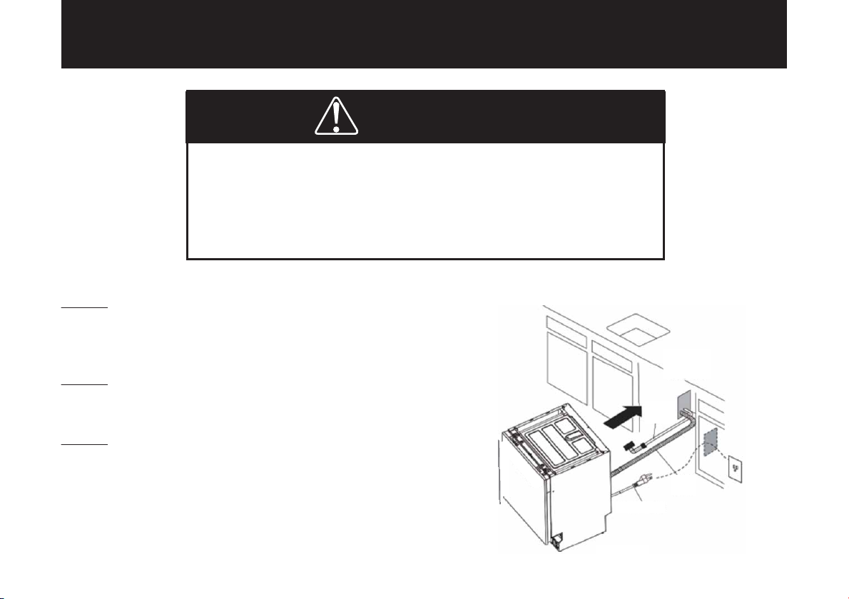
3. As shown in Figure F, connect one end of the inlet line
(A) to the 3/4-inch FHT (B) and connect to the dishwasher.
4. Run the other end of the inlet line through the hole in the
cabinet. If the shut-off valve is 3/8 inch I.D, the inlet line can
be directly connected to the shut-off valve.
5. Adjust the water heater so that it delivers water
temperature between 120°F (49°C) and 150°F (65°C).
6. Flush the water line to clean out debris.
Important! Make sure there are no sharp bends or kinks in
the water line, which might restrict water flow.
Figure F
CAUTION
• The Water supply line pressure must be 6-145 psi.
• The Water heater should be set to deliver 120°F (49°C) to 150°F (65°C) water temperature to the dishwasher.
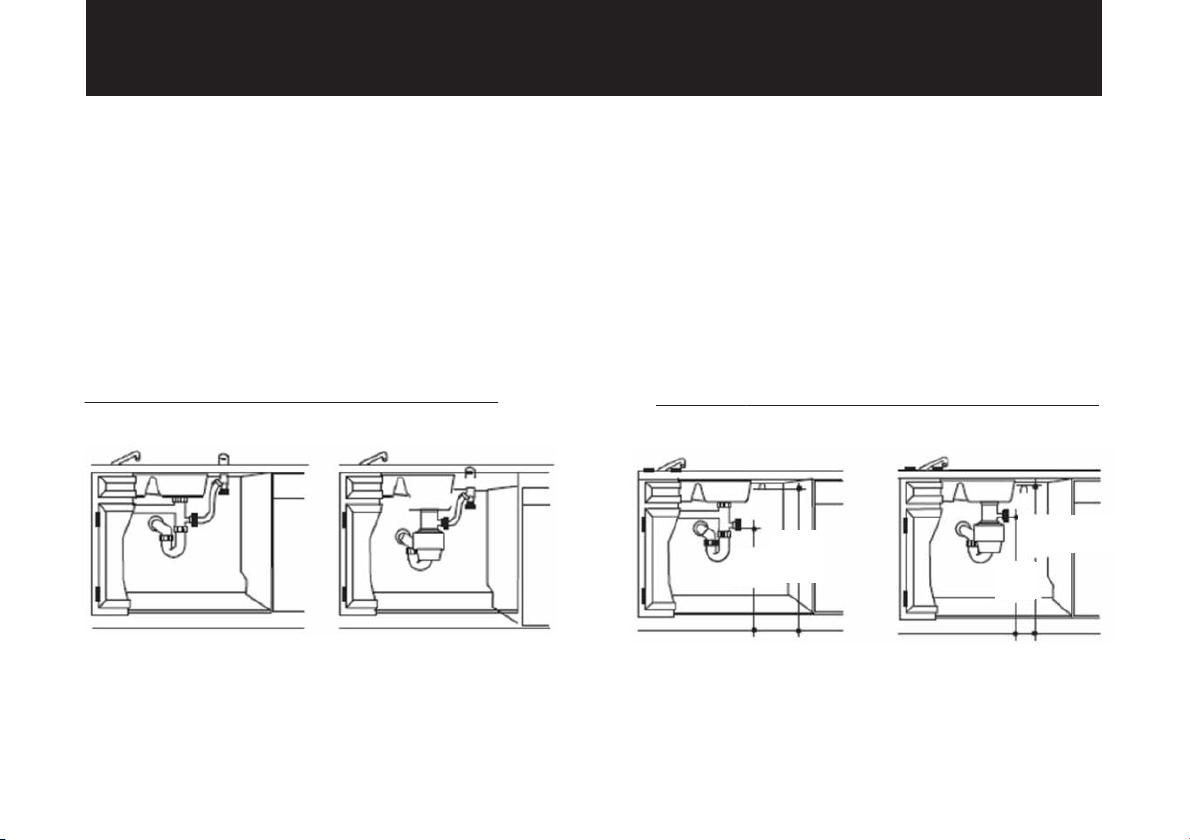
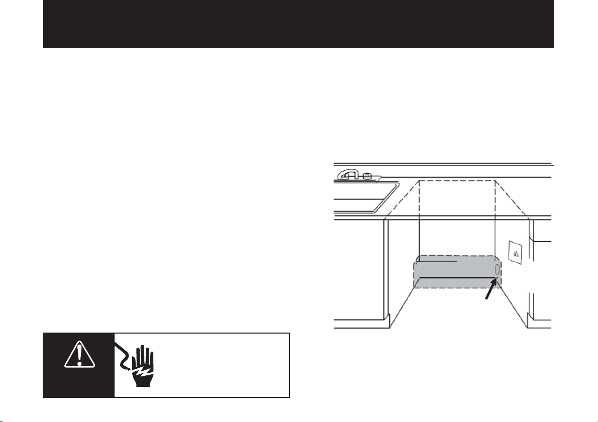
• The Water supply hose may enter from either side, within the shaded area shown in Figure F.
Hot
Cabinet Face
CABINET PREPARATION
Drill a 14⁄5" diameter hole in the cabinet (Figure F) for
the water supply line.
Opening the door will cause the
dishwasher to tip forward. Do not open
the door until you are ready to install
the dishwasher. If it is necessary to
open the door, hold the top of the
dishwasher securely with one hand, and
hold the door with the other hand.
Shut-off Valve 14⁄5"Dia. Hole (Max)
7

INSTALLATION
ELECTRICAL SHOCK HAZARD
WARNING
• DISCONNECT ELECTRICAL POWER AT THE CIRCUIT BREAKER BOX OR FUSE
BEFORE INSTALLING THE DISHWASHER.
• ELECTRICALLY GROUND THE DISHWASHER.
• FAILURE TO DO SO CAN RESULT IN DEATH, FIRE, OR ELECTRICAL SHOCK.
Maximum Drain
Hose Length 10”
Drain Hose
Water Line
Power Cord
STEP 1
Disconnect electrical power at the fuse box or circuit
breaker box before installing the dishwasher.
STEP 2
Shut off the water supply to the dishwasher.
STEP 3
• Insert the drain hose into the cabinet wall hole.
• Insert the power cord into the other cabinet wall hole.
TIP: Position water line and house wiring on the floor
to avoid interference with the base of the dishwasher.
8

STEP 4
• Slide the dishwasher into the opening a few inches at
a time.
DO NOT PUSH AGAINST FRONT PANEL WITH KNEES. IT
WILL CAUSE DAMAGE TO THE DOOR.
STEP 5
• Check to make sure that the power cord and hoses are
secure under the dishwasher and not pinched or in
contact with other dishwasher components.
• Push the dishwasher into the cabinet. The front
corners of the dishwasher door should be flush with
cabinet doors. Be careful not to dent front panels with
knees or damage countertop or cabinets with dish-
washer parts.
• As you proceed, pull the drain hose through the open-
ing under the sink. Stop pushing when the dishwasher
is a few inches forward of adjacent cabinetry.
• Make sure the drain hose is not kinked under the dish-
washer, and there is no interference with the water line
and wiring or any other component.
STEP 6
The dishwasher must be level for proper dish rack
operation and wash performance.
• Place the level on the door and rack track inside
the tub as shown to check if the dishwasher is level.
• Adjust the height by turning the feet to make sure
the dishwasher is level.
Check Level
Check Level
Front to Back
Side to Side
Reposition
Dishwasher
9

STEP 7 - OPTIONAL
You can secure the dishwasher to the cabinet with
the provided self-taping screws. Open the dishwash-
er door, tighten the 4 screws into the outer frame of
the dishwasher, and place the 4 hole-plugs on top of
the screws, as shown in the drawing below.
TIP: Pull the lower rack out about halfway. The rack
should not roll forward or back into the dishwasher. If
the rack rolls in either direction, the dishwasher must
be leveled again.
Adjust the back feetAdjust the front feet
ST4"26
hole plug
If a longer drain hose is required, add up to 42'' (1
meter) of length for a total of 10 ft. (3 meters) to the
factory-installed hose. Use 5/8'' (1.6 cm) or 7/8'' (2.2
cm) inside diameter hose and a coupler to connect
the two hose ends. Secure the connection with hose
clamps.
NOTE: TOTAL DRAIN HOSE LENGTH MUST NOT
EXCEED 10 FEET (3.6 METERS) FOR PROPER DRAIN
OPERATION.
STEP 8
The drain hose molded end will fit 5/8" (1.6 cm), 3/4”
(1.9 cm), or 1" (2.5 cm) diameter connections on the
air gap, waste tee, or disposer. Cut on the marked line
as required for your installation.
IMPORTANT: Do not cut the corrugated portion of the
hose. Cutting Lines
Hose Clamp
Coupler Hose Clamp
10

Remove Disposer Plug
WARNING
STEP 9
• Plug the Power supply cord into a grounded 3
prong outlet.
• Make sure the socket is compatible with the plug
of the appliance; the socket must have an earthing
wire and should be able to hold 120V/13A, other-
wise, damage or accidence may occur. Other elec-
tric appliances must not use the same socket as the
dishwasher.
IMPORTANT:
When connecting the drain line to the disposer,
check to be sure that the drain plug has been
removed.
DISHWASHER WILL NOT DRAIN IF THE PLUG IS
LEFT IN PLACE.
Water Line Connection
Connect drain line to the air gap, waste tee, or
disposer using one of the previously determined
methods.
Method 1
Air gap with waste tee or disposer
Disposer Installation
Method 2
High drain loop with waste tee or disposer
Draining Hose Hanger
Waste Tee Installation
Draining Hose Hanger
Waste Tee Installation Disposer Installation
ELECTRICAL SHOCK HAZARD
Plug into a grounded 3 prong outlet.
Do not remove the ground prong.
Do not use an adapter.
Do not use an extension cord.
Failure to follow these instructions can
result in death, fire, or electrical shock.
11

STEP 10
Perform a PRE-TEST by reviewing this list after install-
ing your dishwasher:
• Check to be sure the power is OFF.
• Open the door and remove all foam and paper pack-
aging.
• Read the Instruction Manual for operating instruc-
tions.
• Check the door opening and closing. If the door does
not open and close freely or tends to fall, check spring
adjustments.
• Make sure that the wiring is secure under the dish-
washer, not pinched or in contact with other compo-
nents.
• Check door alignment with tub. If the door hits the tub,
level the dishwasher.
• Pull the lower rack out about halfway. The rack should
not roll back or forward on the door. If the rack moves,
adjust the leveling legs.
• Check door alignment with the cabinet. If the door hits
the cabinet, reposition or relevel the dishwasher.
• Make sure that the water supply and drain lines are
not kinked or in contact with other components. Contact
with the dishwasher frame could cause noise.
• Turn on the sink hot water faucet and verify water
temperature.
• Incoming water temperature must be between 120°F
(49°C) and 150°F (65°C). A minimum of 120°F (49°C)
temperature is required for best wash performance.
• Turn on the water supply. Check for leaks. Tighten
connections if needed.
STEP 11
Perform the WET-TEST by following these instruc-
tions:
• Plug the power cord into the outlet.
• Power on and select the “Rinse” wash program.
• Close the door and press the “Start” button.
• Check to be sure that water enters the dishwash-
er. If water does not enter the dishwasher, check if
the water and the power are turned on.
• Check for leaks under the dishwasher. If a leak is
found, turn the power supply off, then tighten
connections. Restore power after the leak is
corrected.
• Check for leaks around the door. A leak around
the door could be caused by door rubbing or hitting
against adjacent cabinetry.
• Reposition the dishwasher if necessary.
• The dishwasher will drain and turn off about 10
to 12 minutes after the first fill. Check the drain
lines. If leaks are found, turn the power off at the
breaker and correct plumbing as necessary.
• Restore power after corrections are made.
• Open the dishwasher door and check if most of
the water has drained. If not, check the drain line for
kinks.
• Run the dishwasher through another fill and
drain cycle.
• Check for leaks and correct if required.
• At the end of the drain, open the door and press
the “Power off” button.
12


Müeller USA
168 Mason Way Unit #4A,
City of Industry, CA 91746
Telephone: (888) 632-9981
E-mail: [email protected]
Web: www.muellerdirect.com
Table of contents
Other Mueller Dishwasher manuals