Muller DTW User manual

DTW
DTW-M
DTW
Justus-von-Liebig-Straße 24
31535 Neustadt - DEUTSCHLAND
E-MAIL: [email protected]
TEL.: (+49) 05032-9672-111
FAX: (+49) 05032-9672-199
Operating Manual
Digital Temperature Transmitter
Digital Temperature Transmitter Page-1
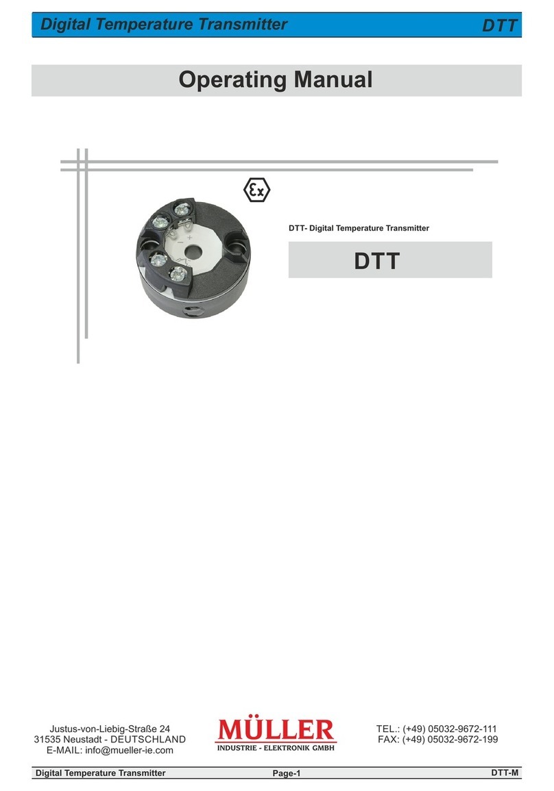
DTW- Digital Temperature Transmitter

DTW-M
1 General (Information, Signs and Abbreviations) 3
2 Transport, Packaging, Storage 3
3 Safety Instructions 4
4 Start-Up, Operation 7
4.1 Function 7
4.2 Before Mounting 7
4.3 Product Label 7
4.4 Mounting 8
5 Electrical Connection 13
5.1 Information 13
5.2 Tools 13
5.3 Auxiliary Power 14
5.4 Maximum Values 14
5.5 Load 14
5.6 Wiring Terminals Assignment 15
6 Configuration 16
7 Troubleshooting 17
8 Maintenance, Dismounting, Return, Cleaning, Disposal 19
9 Technical Data 20
10 Dimensions 26
11 Accessories 27
11.1 Available Accessories 27
11.2 Connection Programming Unit 28
11.3 Configsoft DT 28
11.4 Software Configuration 29
Content
Digital Temperature Transmitter Page-2

DTW-M
Check the device for any damage that may have been caused during transportation.
Report obvious damage immediately!
- These operation instructions contain important information on handling the DTW transmitter.
Working safely requires that all safety instructions and work instructions are observed.
- Skilled personnel must have carefully read and understood the operating instructions prior to beginning
a ny work.
3
-The operating instructions are part of the product and must be kept in the immediate vicinity of the DTW and
readily accessible to skilled personnel at any time.
- Observe the relevant local accident prevention regulations and general safety regulations for the DTW
temperature transmitter range of use.
- If the serial number gets illegible (e. g. by mechanical damage), the retraceability of the device becomes
impossible.
- The temperature transmitters described in this operating manual are carefully designed and manufactured using
state-of-the-art technology. Every component undergoes strict quality inspection in all stages of manufacture.
- The manufacturer's liability is void in the case of any damage caused by using the product contrary to its
intended use, non-compliance with these operating instructions, unauthorised modifications to the DTW or
assignment of insufficiently qualified skilled personnel.
- Norms applied for Ex-protection: EN 60079-0:2012+A11:2013 General Requirements
and EN 60079-11:2012 Intrinsic Safety „i“
- Our company is certified according to ISO 9001:2015
- More information is available under www.mueller-ie.com
- Relevant data sheet: DTW
1 General
Digital Temperature Transmitter Page-3
1.1 For Your Information
1.2 Signs and Abbreviations
!
i
!
Warning!
Noncompliance can cause injuries to persons and/or the demolition of the device. There can be a
danger to life.
Attention!
Noncompliance can cause a faulty operation of the device or lead to property damage.
Information!
Noncompliance can have influence on the operation of the device or cause unintentional reactions of
the device.
Danger!
There is a risk of serious or fatal injury caused by electrical power if the safety instructions are not
complied with.
Danger!
Potential dangerous situation in an area exposed to explosion hazards. Noncompliance can lead to
death or heavy injuries!
Warning!
There is a potential for dangerous situations resulting in burns from hot surfaces or liquids. Please
avoid!
Warning
Danger
Warning
!
Attention!
Damages caused by incorrect handling
Incorrect handling can cause property damage and light injuries.
- Do not use DTW transmitters with visible damage!
Danger
2 Transport, Packaging, Storage
2.1 Transport

DTW-M
Digital Temperature Transmitter Page-4
3 Safety Instructions
3.1 Intended Use of the Product
!
Before installation, commissioning and operation select the appropriate digital DTW temperature
transmitter in terms of function and equipment.
Warning
The device has been designed and built solely for the intended use described here and may only be used
accordingly.
The technical specifications contained in these operating instructions must be observed. Improper handling or
operation of the device outside of its technical specifications requires the device to be taken out of service immediately
and an inspection by the manufacturer.
When the device is transported from a cold into a warm environment, the formation of condensation may cause the
device to malfunction. Before putting it back into operation, wait for the device temperature and the room temperature
to equalise.
The manufacturer shall not be liable for claims of any type based on operation contrary to the intended use.
!
Warning
3.2 Personnel Qualification
For installation and start-up of the DTW the personnel has to be familiar with the relevant regulations and directives of
the country and must have the required qualification. They must have knowledge of measurement and control
technology, have to be acquainted with electric circuits, are capable of carrying out the work described and can
independently recognise potential hazards.
The personnel needs to have the proper training for their work environment and has to comply with the current
regulations for safety at work as prescribed by law!
Working with devices for areas exposed to explosion hazards requires specialist knowledge!
The personnel needs to have knowledge about types of ignition protection, regulations and directives for equipment in
areas exposed to explosion hazards. Depending on operating conditions they need to have the corresponding
knowledge, e. g. of corrosive media.
Risk of injury if qualification is insufficient
Improper handling can result in considerable injuries and damage to equipment.
- The activities described in these operating instructions may only be carried out by skilled personnel who
have the qualifications described below.
- Keep unqualified personnel away from hazardous areas.
iMore safety instructions can be found in the individual chapters.
Allowed storage conditions:
- Storage temperature: -40...+85 °C
- Humidity: 95 % r. h. (condensation allowed)
For longer term storage avoid the following influences:
- Direct sunlight or proximity to hot objects
- Mechanical vibration, mechanical shock (rough deployment)
- Soot, vapour, dust and corrosive gases
If possible, store the device in its original package or an equivalent one
2.3 Storage
Do not remove packaging until just before mounting. Keep the packaging as it will provide optimum protection during
transport (e. g. change in installation site, returns).
2.2 Packaging
2 Transport, Packaging, Storage (Continued)

DTW-M
3 Safety Instructions (Continued)
Digital Temperature Transmitter Page-5
!
!
3.3 Special Hazards
In addition to all standard regulations, the appropriate existing codes or regulations must also be
followed.
If you do not comply with the appropriate regulations, serious injuries and/or damage can occur!
A protection from electrostatic discharge (ESD) is required.
The proper use of grounded work surfaces and personal wrist straps is required when working with
exposed circuitry (PCB, printed circuit boards), in order to prevent static discharge from damaging
sensitive electronic components.
Do not use this instrument in safety or emergency stop devices. Incorrect use of the device can result in
injury.
There is a danger of death caused by electric current.
Upon contact with live parts, there is a direct danger of death.
Electrical instruments may only be installed and connected by skilled electrical personnel.
Operation using a defective power supply unit (e.g. short circuit from the mains voltage to the voltage
output) can result in life-threatening voltages at the device.
Warning
Warning
!
Warning
Danger
3.4 Responsibility of the Operating Body
There is danger to life caused by areas exposed to explosion hazards. Situations leading to death or
heavy injuries are possible.
The instrument is used in the industrial sector. The operatoring body is therefore responsible for legal obligations
regarding safety at work.
The safety instructions within these operating instructions, as well as the safety, accident prevention and
environmental protection regulations for the application area must be maintained.
The operatoring body is obliged to maintain the product label in a legible condition.
The responsibility for classification of zones lies with the operatoring body and not the manufacturer/supplier of the
equipment.
Danger

DTW-M
BVS 15 ATEX E 139 X
IECEx BVS 15.0112X
3 Safety Instructions (Continued)
Digital Temperature Transmitter Page-6
3.5 Ex-Marking and Approval
Danger!
Danger to life caused by loss of explosion protection
Non-compliance with these instructions and their contents can lead to loss of explosion protection.
- Observe the safety instructions and further explosion instructions in these operating instructions.
- Follow the requirements of the ATEX-directive.
- Observe the information given in the applicable type examination certificate and the relevant
country-specific regulations for installation and use in hazardous areas (e.g. IEC 60079-14, NEC,
CEC).
Please make sure to read the operating manual before mounting and start-up of the DTW-transmitter!
Check whether the classification is suitable for the application. Comply with the relevant national regulations.
Model Overview of European Approvals
Danger
II 1G Ex ia IIC T6...T4 Ga
II 1D Ex ia IIIC T135 °C Da
II 2(1)G Ex ia [ia Ga] IIC T6...T4 Gb
II 2(1)D Ex ia [ia Da] IIIC T135 °C Db
For an explanation of the type code,
see data sheet, section Order Code.
Type
Ex-Marking
Ignition Protection Type
DTW head version
DX00XXX01
Intrinsically safe equipment
DTW rail version
DX11XXX01
Intrinsically safe equipment

DTW-M
i
Müller Industrie-Elektronik GmbH - D-31535 Neustadt
Made in Germany
Art.Nr.: 600-00548 DX11XXX01
Tel.: +49 5032 /9672-0
SN.: 0000.11/17-1.0- 000
Input : Pt 100 DIN (3 w)
Range : 0...150 °C PN.: 1A00KOR7U3B
Output : 4...20 mA Tamb: -40...85/70/55 °C / T4/T5/T6
Tamb: 550/650/750 mW / -40...85/70/40 °C
Supply : 10...35 VDC Date : 2017-11
BVS 18 ATEX E012X
II 2(1)G Ex ia [ia Ga] IIC T6...T4 Gb
II 2(1)D Ex ia [ia Da] IIIC T135 °C Db
Next Calibration : 11 / 18 0044
Made in Germany
Art.Nr.: 600-00999
DTW - DX0000001
Tel.: ++49 5032 /9672-0
SN.: 1A00KOR7U3B
2017-11 DC 10...35 V Tamb: -40...85/70/55 °C / T4/T5/T6 II 1G Ex ia IIC T6...T4 Ga
31535 Neustadt am Rübenberge Tamb: 550/650/750 mW / -40...85/70/40 °C II 1D Ex ia IIIC T135 °C Da
Next Cal.: 11 / 18
BVS 18 ATEX E012X
0044
- Check if the DTW transmitter was delivered in complete assembly.
- Inspect the DTW for possible damage during transportation. Should there be any obvious
damage, inform the transport company and supplier immediately.
- Keep the packaging, as it offers optimal protection during transportation.
- Make sure to protect the connecting contacts from damage.
The digital temperature transmitter DTW is a universal measuring transmitter for resistance thermometers and
potentiometers. It is configurable via PC. The device transforms resistance values or relations (potentiometer)
into a proportional current signal. At the same time the sensors are constantly tested to ensure faultless operation.
The temperature transmitter complies with the requirements of:
- Explosion protection (varies with version)
- Electromagnetic compatibility according to NAMUR-recommendation NE21
- Signaling at analog output according to NAMUR-recommendation NE43
- Sensor break signaling according to NAMUR-recommendation NE89 (Corrosion monitoring of sensor
connection)
4 Start-Up, Operation
Digital Temperature Transmitter Page-7
4.1 Function
4.2 Before Mounting
4.3 Product Label (Example)
Art.Nr. : Item number
SN : Serial number
PN : Part number
Rail version DX11XXXXX
Head version DX00XXXXX
iThe product labels as
depicted here are
subject to change and
do not necessarily
represent the final form.
Note: Ex-markings and
type code are always
included.

DTW-M
4 Start-Up, Operation (Continued)
Digital Temperature Transmitter Page-8
4.4 Mounting
i- Check the delivery immediately for completeness and obvious faults.
- If parts are missing or if there are faults, contact the transport company and supplier immediately.
4.4.1 Special Conditions for Safe Use (Ex ia)
Installation in Secure Area
- Mount the transmitter in casing with at least protection level IP20, according to EN/IEC 60529.
- The electrical connections of the casing have to comply to the relevant parts of EN/IEC 60079-11.
- Connection parts or connectors with breaking capability for the intrinsically safe current circuits have to be
arrayed according to the relevant parts of EN/IEC 60079-11.
Installation in Areas Requiring an EPL of Ga (Zone 0), Gb (Zone 1) or Gc (Zone 2)
- Mount the transmitter in casing suitable for mounting in zone 0 or zone 1. The transmitter casing has to
provide at least protection level IP20 according to EN/IEC 60529. Additionally, the casing has to eliminate
electrostatic discharges.
- The electrical connections of the casing have to comply to the relevant parts of EN/IEC 60079-11.
- Connection parts or connectors with breaking capability for the intrinsically safe current circuits have to be
arrayed according to the relevant parts of EN/IEC 60079-11.
Installation in Areas Requiring an EPL of Da (Zone 20) or Db (Zone 21)
- Mount the transmitter in casing suitable for mounting in zone 20 or 21. The transmitter casing has to provide at
least protection level IP6x according to EN/IEC 60079-0. Additionally, the casing has to eliminate electrostatic
discharges.
- The electrical connections of the casing have to comply to the relevant parts of EN/IEC 60079-11.
- Connection parts or connectors with breaking capability for the intrinsically safe current circuits have to be
arrayed according to the relevant parts of EN/IEC 60079-11.
Danger!
Danger to life by explosion!
Working in flammable atmospheres can cause explosion hazards, which may lead to death.
- Conduct set-up work only in areas without explosion hazards!
- In areas with explosion hazards only use DTW-transmitters approved for this specific type of
hazardous area.
Please comply with the approval on the product label!
Gefahr

DTW-M
4 Start-Up, Operation (Continued)
Digital Temperature Transmitter Page-9
4.4.1 Special Conditions for Safe Use (Ex ia, Continued)
Transmitters with ia-marking may also be used in supply circuits of type ib with the same connection parameters.
With this, the entire measuring circuit (including the sensor circuit) is an ib circuit.
DTW-transmitters which were operated with supply circuits of type ib may not be re-used with supply
circuits of type ia.
The external wiring has to be suitable for the temperature range of the end-use application! (max. 85 °C)
The conductor cross section has to be a minimum of 0.14 mm²!

DTW-M
4 Start-Up, Operation (Continued)
Digital Temperature Transmitter Page-10
!
i
4.4.2 Grounding
Property damage by electrostatic charge!
Please observe safety measures according to DIN EN 61340-51/-3 to avoid a electrostatic charge!
During running operation electrostatic charges can occur. Please take actions to avoid electrostatic
discharges on wiring terminals. The discharges can lead to temporary corruption of measurement
values.
- Install DTW head version only in grounded thermometer-heads!
- The connection of a resistance sensor (e. g. Pt100) to the DTW rail version is made with shielded
wiring
- The shielding has to be bonded with the casing of the grounded thermometer.
Only qualified personnel is allowed to work on the electronics.
Grounding DTW Head Version
Install the temperature-transmitter
DTW only in grounded
thermometers!
looped circuit
Connecting Head BSZ
grounded

DTW-M
grounded DTW
Field Housing /
Switch Cabinet
potential equalization
sensor cable
shielding grounded
sensor
4 Start-Up, Operation (Continued)
Digital Temperature Transmitter Page-11
4.4.2 Grounding (Continued)
Grounding DTW Head Version Shielded
Grounding DTW Rail Version Shielded
Connecting Head BSZ
Please note:
In applications with heightened EMC-requirements the application of shielded wire between DTW-transmitter and
sensor is advisable. This is especially important when the EMC-requirements are combined with long leads to the
sensor. See illustrations on this page.
The DTW rail version and long lead lengths over 30 m make a shielded wire mandatory.
shielding grounded
grounded
well with sensor
potential equalization
sensor cable
Field Housing /
Switch Cabinet
grounded DTW

DTW-M
4 Start-Up, Operation (Continued)
Digital Temperature Transmitter Page-12
4.4.3 Mounting DTW Head Version
Mounting inside Connecting Head
iDo not exceed a torque of 1 Nm when mounting the DTW head version!
DTW head version transmitters are meant to be mounted on a gauge slide in DIN-connection heads type B with
extended mounting space.
The bonding wires of the gauge slide have to be ca. 50 mm long and insulated versions of the wire.
Mounting Example
Put the gauge slide with mounted DTW-transmitter into
the protective fitting and fasten it using screws in
pressure springs.
Mounting in Connecting Head Cover
When mounting a connection head inside the cover, use suitable screws and matching washers.
Mounting with Top Hat Rail Adapter
A mechanical adapter is available as accessory. It can be used to fasten DTW head version transmitters to a top
hat rail. (See chapter 11, Accessories)
4.4.4 Mounting DTW Rail Version
Fasten the rail casing by simply latching it onto a 35 mm top hat rail without any other tools needed. The rail has to
comply with EN 60175.
Dismounting is done by unlocking the fixing element.

DTW-M
5 Electrical Connection
Digital Temperature Transmitter Page-13
5.1 Information
Danger
Danger!
Danger to life by electric current
Touching live parts results in immediate danger to life!
- Please only use specialist personnel to install and mount the device!
- Operation using a defective power supply can cause life-threatening voltages at the device.
- Conduct electrical installation only in dead voltage condition.
- The bonded wires have to be connected properly. Please control the connections, only properly
connected wires can guarantee full functionality.
The DTW transmitter is protection class 3 equipment for the connection to low voltages which are separated from
supply voltage or voltages higher than AC 50 V, respectively DC 120 V.
- A connection to SELV- or PELV-current circuits is recommended.
- Alternative recommendation: Use protective measures from HD 60346-4-41 (DIN VDE 0100-410)
Alternative for North America
A connection to Class 2 Circuits and Class 2 Power Units according to CEC or NEC is possible.
Please note:
The galvanic isolation used in the device cannot protect against electrical impulses as defined by EN 61140.
5.2 Tools Required for Screw Terminals
Type
Screwdriver
Tightening Torque
DTW DX00XXXXX
(head version)
Cross-head (Pozidriv)
Size 2 (ISO 8764)
0,5 Nm
DTW DX11XXXXX
(rail version)
Flat-tip, 3 x 0,5 mm (ISO 2380)
0,5 Nm

DTW-M
0824 30 35
744
1023
1256
0
Non-
Ex-devices
Digital Temperature Transmitter Page-14
5 Electrical Connection (Continued)
5.3 Auxiliary Power
Auxiliary Power, 4...20 mA Current Loop
The DTW is a 2-wire powered digital temperature-transmitter and can, depending on version, be supplied with
different auxiliary power.
Recommendation when using stranded wires:
- Please use crimp contacts.
Please note:
- The reverse voltage protection (reverse voltage on clamps + and -) prevents the destruction of the device.
DTW
DXXXXXXX0
DC 35 V
DTW
DXXXXXX01
DC 30 V
5.4 Maximum Values
Minimal Terminal Voltage
DC 8 V
Please note:
- Do not allow the load to become too large, or the terminal voltage at the device at higher currents will fall
too low.
Auxiliary power U : DC 8...35 V
B
Load R : R ≤ (U - 8 V) / 0,0215 A
A a B
with R in Ω and U in V
A B
For Ex-applicable power ratings see chapter
Technical Data, p. 24 - 25
The allowed load depends on the voltage of
the loop supply.
5.5 Load Diagram
Load R in Ω
A
Min. voltage
Auxiliary Power U in V
B
Operating
voltage
Ex-devices

Digital Temperature Transmitter Page-15
5 Electrical Connection (Continued)
5.6 Wiring Terminals Assignment
Input
Output
4...20 mA-loop
Potentiometer
4-wire
1
-
-
+
+
4
3
2
2
3
2
3
4
4
3
2
mA
3-wire 2-wire
Resistance Thermometer/
Resistance Sensor
in
+
-
13
24
+
-
3
1
4
2
+
+
2
4
1
3
-
-
mA - +
1 2
3 4
Connection Programming Unit
DTW Head Version DTW Rail Version
Resistance Thermometer (RTD) and Resistance Sensor
Possible are connections for a resistance thermometer in 2-,3- or 4-wire connection, or for a potentiometer in 3-
wire connection.
- Configure the sensor input of the transmitter after the actually used type of input circuit (e. g. 2-wire). Otherwise
the complete use of all input wire compensation options is impossible.
- A wrong configuration can lead to additional measurement errors.
iSafety-related parameters for the connection of voltage supply and sensors can be found in chapter
Technical Data, p. 20

DTW-M
Digital Temperature Transmitter Page-16
6 Configuration
6.1 Configuration
6.3 Configuration via PC
The DTW temperature transmitter can be configured via a PC's USB-interface, by using the programming unit
and the configuration software.
iThe required Windows device drivers for the programming unit will be installed automatically when
running DT Configsoft.
6.2 Configurable Monitoring Functionality
Configurable are:
- Sensor type
- Sensor connection
- Measurement range
- Unit
- Signalling
- Measurement range monitoring
- Damping
- Write protection
- TAG-numbers
- 2-point scaling
The DTW temperature transmitters will be delivered with a factory setting (see data sheet DTW) or configured
according to customer specifications.
- Please write down any modifications of your configuration on the product label! Use a water-resistant fibre-tip
pen.
iTo configure the DTW a simulation of the input value is not necessary. Only for the functional test do
you need to simulate the sensor.
Measurement range monitoring:
If measurement range monitoring is active, an error is signaled on the current loop if the measured value is either
below or above the measurement range.

DTW-M
i
!
7 Troubleshooting
Note: In case of unjustified reclamation an additional charge is possible.
Make sure the unit is working properly after every setting change. In case the error persists, send the device in for
repair (or replace the unit).
Returned goods: Clean dismounted devices. See also chapter 8 for more details.
- Do not use any pointed or hard objects for cleaning to prevent damage to the electrical contacts.
- Verify in advance if the right voltage supply and the right type of wiring has been chosen.
- For contact data, see data sheet DTW or cover/backside.
Caution!
Physical injuries, property- and environmental damage
If faults can't be eliminated using the following actions, take the device out of operation immediately!
- Please make sure there is no more signal present and protect the device against accidental operation.
- Contact the manufacturer
- Only the manufacturer is allowed to conduct repairs!
- Please note the advice under chapter 8, p. 19 and add a short error description to the temperature
transmitter.
- The error description should include details to environmental conditions, duration time of operation
and error incidents.
Warning
Digital Temperature Transmitter Page-17
Danger!
Danger to life caused by explosion
Working in flammable atmospheres can cause danger to life by explosion hazards.
- Only conduct fault repairs in non-flammable atmospheres!
Danger

DTW-M
7 Troubleshooting (Continued)
Digital Temperature Transmitter Page-18
Fault Tree
Current loop not closed
Transmitter not connected
Process temperature out of
measurement range
Sensor break or short circuit
Sensor connected incorrectly
Wrong transmitter configuration
Wrong 2-, 3- or
4-wire connection
Wrong sensor type
Wrong temperature-
range
Sensor
= RTD
Sensor
= TC Wrong compensation
Current value is correct, but a temperature
drift is noticeable while transmitter is heating
up or cooling down
4 mA < | < 20 mA
but wrong values
I < 4 mA
I > 20 mA
Voltage supply connected
incorrectly (wrong polarity)
I = 0 mA
Current value falls while measured
temperature rises (and reversed)
Wrong polarity of
thermocouple Capacitive or inductive
coupling via the sensor
Capacitive or inductive
coupling via the current
loop
Electromagnetic
interferences
Current value is unstable and
changes within seconds
Load too high
Current value is okay at low values,
but too low at higher temperatures

DTW-M
8 Maintenance, Dismounting, Return, Cleaning, Disposal
Digital Temperature Transmitter Page-19
8.5 Disposal
Dispose device components and packaging materials in accordance with the respective waste treatment
and disposal regulations of the region or country to which the DTW temperature transmitter is supplied.
Collect electrical and electronic parts separately. Separate metals and plastics. Dispose of printed circuit
board assemblies professionally.
!
!
Property damage!
Abrasive cleaners or corrosive solvents can damage the contacts.
- Power down and create dead voltage condition on the device before cleaning.
- Before returning the device needs to be free of hazardous materials like acids, brines, solvents,
etc.!
i
i
8.4 Cleaning
Warnung
- The DTW temperatur transmitters are maintenance-free.
- Only the manufacturer is allowed to conduct repairs.
- The electronics are completely potted. They do not contain any repairable or replacable parts.
Before returning the device, follow the instructions in chapter 8.4.
To return a device, use the original packaging or something comparable.
To protect against damages, use anti-static foil, insulating material or identification as sensitive
measurement equipment.
If possible, please add a bag with drying mass.
Clean the device regularly to keep it free of hazardous materials. Please keep the electrical contacts
dry and clean!
Create dead voltage condition on device. Disconnect electrical connections. Use chapter 4.4 in reversed order.
8.1 Maintenance
8.2 Dismounting
8.3 Return

DTW-M
9 Technical Data
Digital Temperature Transmitter Page-20
Input
Resistance thermometer: Sensor: Pt100 / Pt1000
Max. configurable measurement range: -200...+850 °C
Min. measuring span: 10 K / 3,8 (only higher value applies)Ω
Measurement current: Max. 0,2 mA
Specification: -2, -3, 4-wire
Max. line resistance: 50 / wireΩ
(only in 3- / 4-wire-circuits)
Configurable: 2-wire-circuit
Standard: IEC 60751:2008
Potentiometer: Sensor: Reed-chains
Max. configurable measurement range: 0...100 % (1...50 k ) Ω
Min. measuring span: 10 % (min. 1 k ) Ω
Measurement current at measuring: Max. 0,1 mA
Specification: 3-wire
Max. line resistance: 50 / wireΩ
Standard: IEC 60751:2008
Output (Analog)
Current signal: 4...20 mA loop
Transmission behaviour: Temperature linearity according to IEC 60751
Current range: 3,8...20,5 mA (NAMUR NE43)
Fault signal: Configurable (NAMUR NE43)
Downscale: <3,6 mA
Upscale: >21,0 mA
Environmental Conditions
Ambient temperature: Standard: -40...+85 °C
Option: -50...+105 °C (only head version without Ex-protection)
Climatic influence: Class: Cx
Standard: IEC 654-1:1993
Ranges: -40...+85 °C, 5...95 % r. F.
Humidity head version: Range: Max. 93 % ±3 % r. F.
Standard: IEC 60068-2-38:2009
Test: Max. temperature change 65 °C / -10 °C
Humidity rail version: Range: Max. 95 % r. F.
Standard: IEC 60068-2-30:2005
Test: Max. temperature 55 °C
Vibration resistance: Range: Amplitude 0,75 mm
Standard: IEC 60068-2-6:2008
Test: Fc: 10...2000 Hz; acceleration 10 g
Shock resistance: Load: 30 g / 11 ms
100 g /6 ms
Standard: IEC 68-2-27:2009
Salt fog: Range: Severity level 1
Standard: IEC 68-2-52::1996
IEC 60068-2-52:1996
Danger!
Danger to life by loss of explosion protection
Noncompliance with instructions for the operation in hazardous areas leads to loss of the explosion
protection.
- Comply with the following limit values and technical specifications!
Danger
Table of contents
Other Muller Transmitter manuals
Popular Transmitter manuals by other brands

GoMax Electronics
GoMax Electronics SP-9018 user manual

NEC
NEC DTU-70 instruction manual

MultiDyne
MultiDyne HD-3500 series instruction manual

Becker
Becker Centronic / B-Tronic EasyControl MC611 Assembly and operating instructions

Motorola
Motorola CP 140 user guide

Monacor
Monacor JTS PT-920BG/5 instruction manual