MULTILINE MURRO User guide

1
Mounting instruction. Montage-instructie. Instruction de montage. montageanleitung
WALL LUMINAIRES
MURRO
!
!
MULTILINE Licht nv
Europaweg 1 –B –3560
Lummen
T +32 (0) 11 450 260
E sales@multiline-licht.com
W www.multiline-licht.com
!
The installation and operation of this luminaire are subject to the national safety regulations. During installation
and re-lamping, the power supply must be disconnected. High voltage on LEDs is possible till 1 minute after
power disconnection !!!
Voor de installatie en werking van dit armatuur dient men rekening te houden met de nationale
veiligheidsvoorschriften. Montage en lampwissel moeten spanningsvrij gebeuren. Hoogspanning op LEDs is
mogelijk tot 1 minuut na het uitschakelen !!!
Afin d'installer et d'utiliser ce luminaire, respectez les normes de sécurité nationales. Pour l'installation ou le
remplacement de la lampe, débranchez l'alimentation. Une haute tension sur des LEDs est possible jusqu'à 1
minute après le débranchement !!!
Für die Installation und den Betrieb dieser Leuchte sind die nationalen Sicherheitsvorschriften zu beachten. Die
Installation und der Leuchtmittelwechsel sollen spannungsfrei erfolgen. Hochspannung auf LEDs ist möglich
bis zu 1 Minute nach dem Abschalten !!!
!
48.16120000-0000
00009

2
!
!
!
!
MULTILINE Licht nv
Europaweg 1 –B –3560
Lummen
T +32 (0) 11 450 260
E sales@multiline-licht.com
W www.multiline-licht.com
Questions ?
Vragen ?
Questions ?
Fragen ?
support@mulitline-licht.com
IMPORTANT REMARKS IN ADVANCE
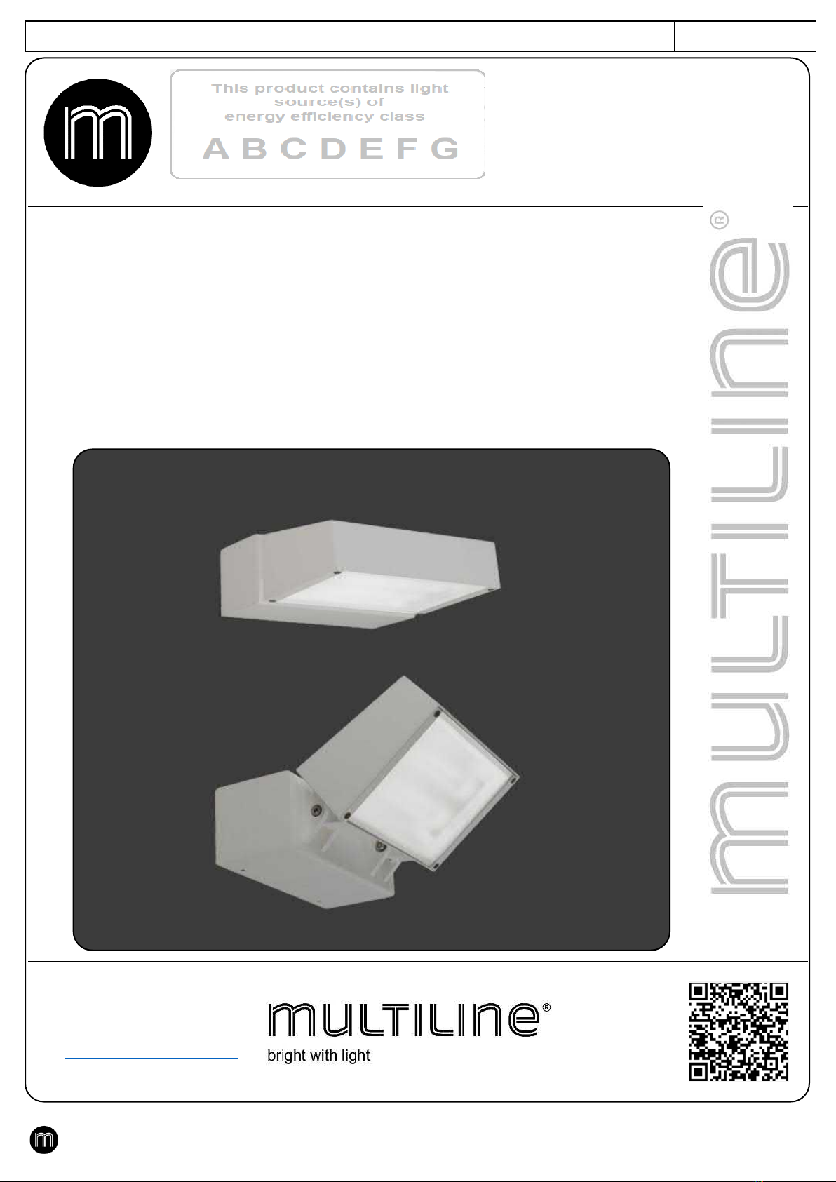
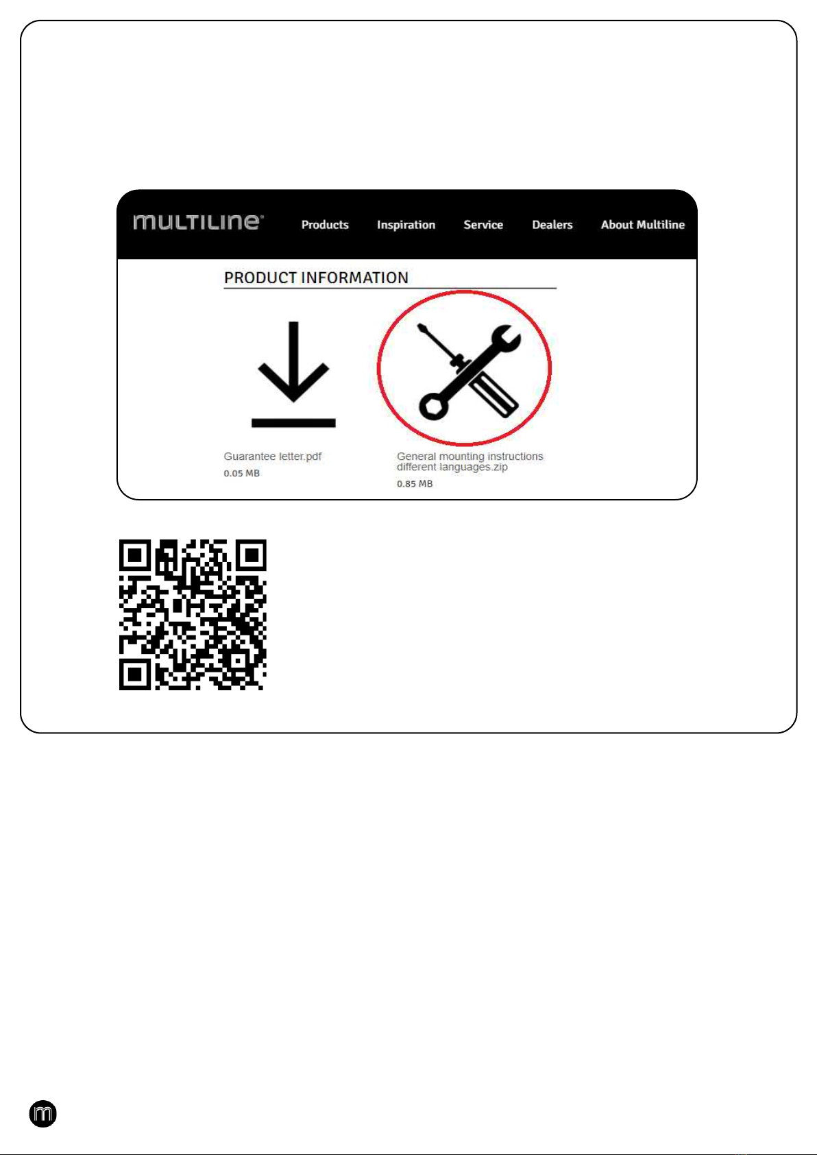
•Check for damage when unpacking and verify labels for correct type. See example at the bottom of the page
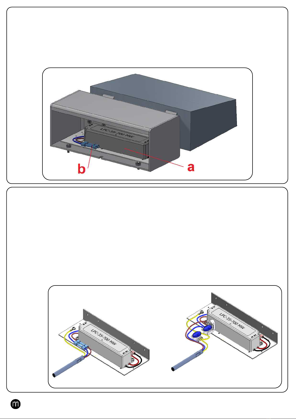
•Use the project lay out and the wiring scheme (for multiple switching circuits) as an installation aid.
•The profile numbers on the lay out correspond with the number on the packaging labels.
•When using in-line couplers or corner connectors (for a 2way, 3way or 4way corner), one of the
adjoining profiles has one or more terminal blocks. The other adjoining profiles have a longer
wiring without terminal blocks. This wiring has to be connected to the terminal block(s) in the
other adjoining profile.
•While connecting the wiring, regard the colour codes as shown on the wiring scheme.
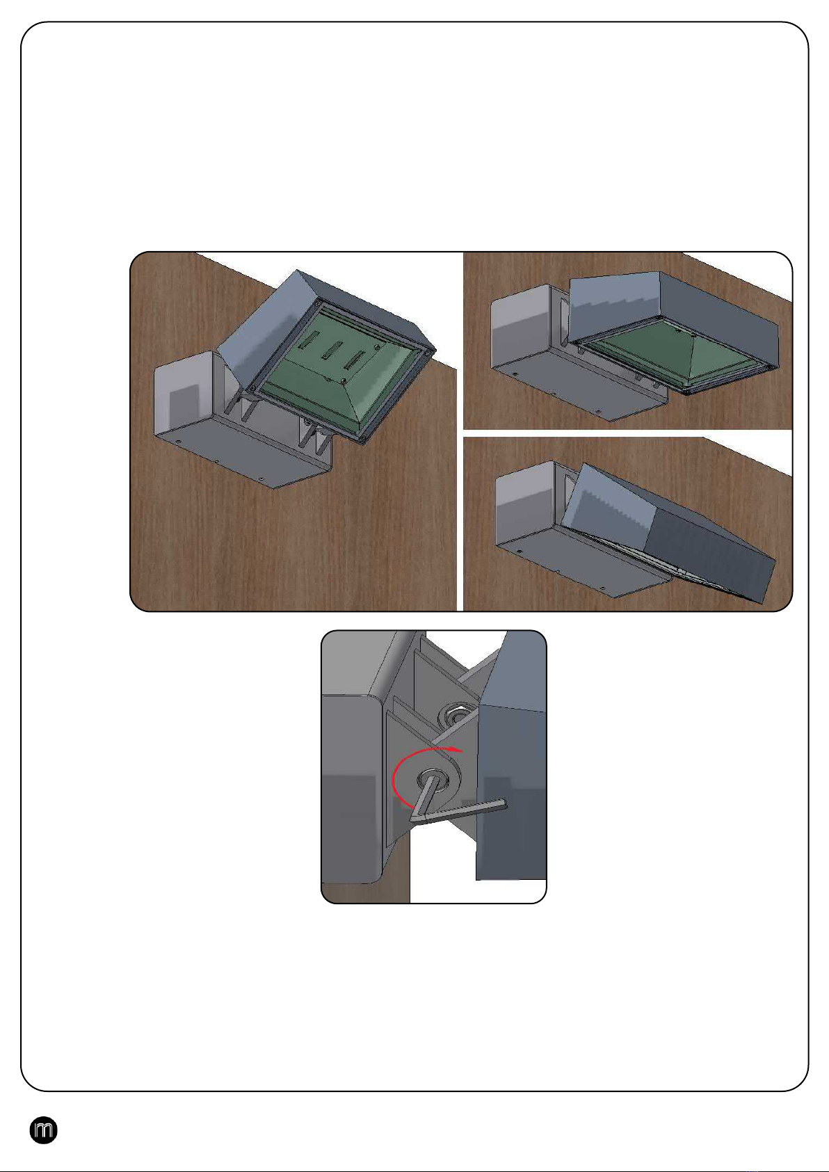
•While putting the cover profiles and/or louvres back into place, connect the earthing cables.
•Remove the protective foil from the reflectors before putting the lamps into use.
•Appropriate ESD (electrostatic discharge) safety measures must be taken.
BELANGRIJKE OPMERKINGEN VOORAF
•Controleer op beschadigingen bij het uitpakken en verifieer de labels voor het juiste type. Zie voorbeeld onderaan blz.
•Gebruik de projecttekening en het bekabelingsschema (bij meerdere schakelkringen) als montagehulp.
•De profielnummers op de tekening komen overeen met de nummers op de stickers van de verpakking.
•Bij gebruik van in-lijn koppelingen of verbindingsstukken (bij een 2weg-, 3weg- of 4weg-verbinding)
is telkens één van de aansluitende profielen voorzien van één of meerdere aansluitklemmen. De
overige aansluitende profielen hebben een verlengde bekabeling zonder aansluitklem. Deze
bekabeling dient te worden aangesloten aan de aansluitklem(men) in het andere aansluitende
profiel.
•Respecteer bij het verbinden van de bekabeling de aangegeven kleurcodes op het bekabelingsschema.
•Sluit bij het terugplaatsen van de afdekprofielen en/of rasters het aardingskabeltje terug aan.
•Verwijder de beschermfolie van de reflectoren alvorens de lampen in gebruik te stellen.
•Geschikte ESD (elektrostatische ontlading) beschermingsmaatregelen moeten genomen worden.
REMARQUES IMPORTANTES PRELIMINAIRES
•Vérifiez les dommages lors du déballage et vérifiez le type d'étiquettes. Voir exemple en bas de page
•Utilisez le dessin du projet et le schéma du câblage (en cas de de plusieurs circuits) comme aide
d’installation.
•Les numéros des profils sur le dessin correspondent avec les numéros sur les autocollants de
l’emballage..
•En utilisant des connecteurs (pour un raccord en 2, 3 ou 4 directions), un des profils est pourvu d’un
ou de plusieurs borniers. Les autres profils sont pourvus d’un câblage plus long sans bornier(s). Ce
câblage doit être connecté au bornier(s) dans l’autre profil.
•En connectant le câblage, il faut respecter les couleurs de câbles comme indiquées sur le schéma de
câblage.
•En remettant les couvercles et les grilles, il faut reconnecter les câbles de terre.
•Enlevez le feuil de protection des réflecteurs avant de mettre en service les lampes.
•Des mesures appropriées de protection contre DES (décharge électrostatique) doivent être prises.
WICHTIGE BEMERKUNGEN VORAB
•Überprüfen Sie beim Auspacken auf Beschädigungen und überprüfen Sie die Etiketten auf den richtigen
Typ. Siehe Beispiel unten auf der Seite.
•Verwenden Sie die Projektzeichnung und das Verdrahtungsübersicht (für mehrere Schaltkreise) als
Installationshilfe.
•Die Profilnummer auf der Zeichnung stimmen mit den Nummern auf den Aufklebern der Verpackung
überein.
•Beim Anwenden von Verbindungsteilen (für 2Wege-, 3Wege- oder 4Wege-Winkel) wird eins der
angrenzende Profile mit einem oder mehreren Anschlußklemmen ausgerüstet. Die übrige
angrenzende Profile haben eine längere Verdrahtung ohne Anschlußklemmen. Diese Verdrahtung
muss an die Anschlußklemmen der andere Profile angeschlossen werden.
•Beachten Sie die Farben der Verdrahtung wie angegeben auf dem Verdrahtungsübersicht.
•Schließen Sie die Erdungskabel der Abdeckprofile und/oder Raster wieder an.
•Entfernen Sie die Schutzfolie der Reflektoren bevor Sie die Leuchtmittel in Betrieb setzen.
•Geeignete Maßnahmen gegen ESD (elektrostatische Entladung) müssen genommen werden

3
MULTILINE Licht nv
Europaweg 1 –B –3560
Lummen
T +32 (0) 11 450 260
E sales@multiline-licht.com
W www.multiline-licht.com
Questions ?
Vragen ?
Questions ?
Fragen ?
support@mulitline-licht.com
table of contents
•Place mounting bracket. Step 1 - Page 4
•Connect power cable. Step 2-3 - Page 5
•Align the luminaire (MURRO-2 only). Step 4 - Page 6
Inhoudstafel
•Bevestigingdbeugel plaatsen. Stap 1 - Pagina 4
•Voedingskabel aansluiten. Stap 2-3 - Pagina 5
•Armatuur richten (enkel MURRO-2). Stap 4 - Pagina 6
table des matières
•Placez le support de montage. Étape 1 - Page 4
•Branchez le câble d'alimentation. Étape 2-3 - Page 5
•Alignez le luminaire (MURRO-2 uniquement). Étape 4 - Page 6
Inhaltsverzeichnis
•Montagewinkel anbringen. Schritt 1 - Seite 4
•Netzkabel anschließen. Schritt 2-3 - Seite 5
•Leuchte ausrichten (nur MURRO-2). Schritt 4 - Seite 6

4
The MURRO luminaire is hung on the wall with a mounting bracket (a). Place the bracket with the short lip facing up (f).
There is an opening (h) in the middle for the lead-through of the power cable (e). Mark the drill hole on the wall, centered in
the slotted holes (g). Tighten the bracket with a threaded bolt (b) and a washer (c). If the left is stuck, you can still fit the
bracket with the right. First, hook the mounting housing over the short lip and lower it fully against the wall. The housing is
secured by screwing in the set screws (d) at the bottom.
De MURRO armatuur wordt met een bevestigingsbeugel (a) aan de muur opgehangen. Plaats de beugel met de korte lip
naar boven (f). In het midden zit een opening (h) voor de doorvoer van de voedingskabel (e). Duid het boorgat aan op de
wand, gecentreerd in de sleufgaten (g). Draai de beugel vast met een draadbout (b) en een rondel (c). Als links vast zit, kan
je met rechts de beugel nog uitpassen. Haak eerst de montagebehuizing over de korte lip en laat ze zakken tot volledig
tegen de wand. De behuizing wordt vastgezet met het indraaien van de stelschroeven (d) onderaan.
Le luminaire MURRO est accroché au mur avec un support de montage (a). Placez le support avec la lèvre courte vers le
haut (f). Il y a une ouverture (h) au milieu pour le passage du câble d'alimentation (e). Marquez le trou de perçage sur le mur,
centré dans les trous oblongs (g). Serrez le support avec un boulon fileté (b) et une rondelle (c). Si la gauche est coincée,
vous pouvez toujours monter le support avec la droite. Tout d'abord, accrochez le boîtier de montage sur la lèvre courte et
abaissez-le complètement contre le mur. Le boîtier est fixé en vissant les vis de réglage (d) en bas.
Die Leuchte MURRO wird mit einem Montagebügel (a) an die Wand gehängt. Platzieren Sie die Halterung mit der kurzen
Lippe nach oben (f). In der Mitte befindet sich eine Öffnung (h) für die Durchführung des Netzkabels (e). Markieren Sie das
Bohrloch an der Wand, zentriert in den Langlöchern (g). Befestigen Sie die Halterung mit einem Gewindebolzen (b) und
einer Unterlegscheibe (c). Wenn die linke klemmt, können Sie die Halterung immer noch mit der rechten montieren. Haken
Sie zuerst das Montagegehäuse über die kurze Lippe und senken Sie es vollständig gegen die Wand ab. Die Befestigung
des Gehäuses erfolgt durch Eindrehen der Gewindestifte (d) an der Unterseite.
STEP 1 :
STAP 1 :
ETAPE 1 :
SCHRITT 1 :

5
The connection is on the wiring of the LED driver (a) in the mounting housing. Remove the connection sockets (b) from the
housing .
De aansluiting zit op de bedrading van de LED driver (a) in de montagebehuizing. Haal de aansluitbussen (b) uit de
behuizing .
La connexion se fait sur le câblage du pilote LED (a) dans le boîtier de montage. Déposer les douilles de raccordement (b)
du boîtier .
Der Anschluss erfolgt an der Verdrahtung des LED-Treibers (a) im Einbaugehäuse. Anschlussbuchsen (b) aus dem
Gehäuse entfernen .
STEP 2 :
STAP 2 :
ETAPE 2 :
SCHRITT 2 :
Connect : (Left) Dismantle the power cable and strip the wires about 10mm, insert the wires into the blue crimp connector
and crimp them with a crimping tool. left or the connector with comb. (Right) Dismantle the power cable, stripping of the
wires is not necessary. Insert the wires into the watertight connector with comb and squeeze with combination pliers. The
comb ensures the connection of the veins.
Anschließen: (Links) Stromkabel demontieren und Adern ca. 10 mm abisolieren, Adern in den blauen Quetschverbinder
einführen und mit einer Crimpzange crimpen. links oder der Stecker mit Kamm. (Rechts) Netzkabel demontieren,
Abisolieren der Adern ist nicht erforderlich. Die Adern in den wasserdichten Stecker mit Kamm einführen und mit einer
Kombizange zusammendrücken. Der Kamm sorgt für die Verbindung der Venen.
Connexion : (Gauche) Démontez le câble d'alimentation et dénudez les fils sur environ 10 mm, insérez les fils dans le
connecteur à sertir bleu et sertissez-les avec une pince à sertir. gauche ou le connecteur avec peigne. (À droite) Démontez
le câble d'alimentation, le dénudage des fils n'est pas nécessaire. Insérez les fils dans le connecteur étanche à l'aide d'un
peigne et serrez avec une pince universelle. Le peigne assure la connexion des veines.
Aansluiten : (Links) Ontmantel de voedingskabel en strip de draden ongeveer 10mm, steek de draden in de blauwe
crimpconnector en knijp ze dicht met een crimptang. links of de connector met kam. (Rechts) Ontmantel de voedingskabel ,
strippen van de draden hoeft niet. Steek de draden in de waterdichte connector met kam en knijp ze dicht met een
combinatietang. De kam zorgt voor de verbinding van de aders.
STEP 3 :
STAP 3 :
ETAPE 3 :
SCHRITT 3 :

6
Type MURRO-1 is a fixed installation. Mounting housing and light module are screwed together. Type MURRO-2 is a wall
model with adjustable hinges for the Tilt movement. Loosen the hinge bolts a little, adjust the lamp to the desired angle and
screw the bolts back on.
Type MURRO-1 is een vaste opstelling. Montagebehuizing en lichtmodule zitten tegen elkaar aangeschroefd. Type MURRO-
2 is een wandmodel met instelbare scharnieren voor de Tilt-beweging. Draai de scharnierbouten een beetje los, stel de
lamp in onder de gewenste hoek en schroef de bouten weer vast.
Le type MURRO-1 est une installation fixe. Le boîtier de montage et le module d'éclairage sont vissés ensemble. Le type
MURRO-2 est un modèle mural avec charnières réglables pour le mouvement Tilt. Desserrez un peu les boulons de la
charnière, réglez la lampe à l'angle souhaité et revissez les boulons.
Typ MURRO-1 ist eine Festinstallation. Montagegehäuse und Lichtmodul werden miteinander verschraubt. Typ MURRO-2
ist ein Wandmodell mit verstellbaren Scharnieren für die Tilt-Bewegung. Lösen Sie die Scharnierbolzen etwas, stellen Sie
die Leuchte auf den gewünschten Winkel ein und schrauben Sie die Bolzen wieder fest.
STEP 4 :
STAP 4 :
ETAPE 4 :
SCHRITT 4 :

7
Additional information regarding mounting can be found on the webpage in the ZIP file:
"General_mounting_instructions_different_languages.zip" via the link: https://www.multiline.be/nl/service/downloads
Extra informatie met betrekking tot de montage kunt u vinden op de webpagina in de ZIP file :
"General_mounting_instructions_different_languages.zip" via de link : https://www.multiline.be/nl/service/downloads
Des informations supplémentaires concernant le montage sont disponibles sur la page Web dans le fichier ZIP :
"General_mounting_instructions_different_languages.zip" via le lien : https://www.multiline.be/nl/service/downloads
Weitere Informationen zur Montage finden Sie auf der Webseite in der ZIP-Datei:
"General_mounting_instructions_different_languages.zip" über den Link: https://www.multiline.be/nl/service/downloads
Additional
:
Extra
Additionnel
:
Zusätzlich:
Other MULTILINE Outdoor Light manuals

MULTILINE
MULTILINE Spy-1 User manual

MULTILINE
MULTILINE Sergeant Series User manual

MULTILINE
MULTILINE Metro User manual

MULTILINE
MULTILINE Clip User manual

MULTILINE
MULTILINE Kubik Series User manual

MULTILINE
MULTILINE 04.870 Series User manual

MULTILINE
MULTILINE Clip-M Series User manual

MULTILINE
MULTILINE Artres User manual
Popular Outdoor Light manuals by other brands

Suneco
Suneco ECO5326LD Series manual

Quoizel
Quoizel SFD8407IB Assembly instruction sheet

Saxby Lighting
Saxby Lighting Bianco LED CCT PIR instruction manual

SolarPath
SolarPath SPBS3 installation instructions

AquaScape
AquaScape 84063 installation instructions

Visual Comfort & Co.
Visual Comfort & Co. CHO2110 Assembly instructions