Multiplex Blend-In-Cup Machine Welbilt KitchenCare... User manual

March 2020
Part Number 9295059
Printed in
The United States of America
Blend-In-Cup Machine®
MA-8-2, MA-8-2BF, MA-8-2AF
Blended-In-Cup® (BIC)
Manual Fill Beverage System
2020 Tune Up - North America
Welbilt KitchenCare®
Tel. 844-724-2273

Qty Required Tools
1 Safety Gloves
1 Oetiker Pliers, Part # 00681815
1 Needle Nose Pliers
1 Phillips & Flat Head Screw Drivers
(Multiple Lengths & Head Sizes)
1 ⁄" or ¼” Drive Socket Set (with ⁄” and ⁄”)
1 Standard Open End Wrench Set
1 Soft Bristle Brush
1 Shop Wet/Dry Vacuum
1 Digital Scale – Capable To Scale In ⁄
1 5 - 6 ft (30 cm) ¼” I.D. X 3/8“ O.D. clear tubing
NORTH AMERICA TUNE UP KIT 000-BIC-01F5-S
• EVERY part in this kit must be used, removed
parts should be left with the manager.
Qty Description Number
9 Valve, dispense outlet, LMS 1706172
9 15.7 oetiker, clamp, product 15.7-706R
2 O-ring, replacement MCP00262
1 Gasket Ice Shaver 3434865
1 Drive belt, Shaver Vitamix 1617 VMP00123
1 Shaver Blade Kit VMP00125
1 Instructions ENG 9295059
1 Instructions FC 9295060
KOREANTUNE UP KIT 000-BIC-01F6-S
Qty Description Number
9 Valve, dispense outlet, LMS 1706172
9 15.7 oetiker, clamp, product 15.7-706R
2 O-ring, replacement MCP00262
1 Gasket Ice Shaver 3434865
1 Drive belt, Shaver Vitamix 1617 VMP00123
1 Shaver Blade Kit VMP00125
1 Instructions ENG 9295059
Notes:
• Additional non-warranty parts used need to
be invoiced on a separate invoice to the site.
Manager must approve additional repairs.
• All right and left references are based o of
standing in front of the unit.
Multiplex
2100 Future Drive
Sellersburg, IN 47172
Phone: 844-724-2273
Fax: 920-683-7592 Page 2 of 13
New Parts
Applicable to MA-8-2, MA-8-2BF, MA-8-2AF

1. Verify operation with staff. Identify any issues
and record on Tune Up Checklist.
2. Remove product from the cabinet and place in
the walk in cooler
3. Prepare a five (5) gallon bucket with luke warm
tap water (no hotter than 105°F/40.5°C) and
cleaning solution. Clean all eight (8) product
fittings and connect the cleaning manifold.
Remove the dispense area drain grate.
Position the dispense shield in the dispense
area.
Using the Easy Touch screen follow the next
steps to clean and rid each of the product lines
of syrup.
• Access the Managers Menu
• Enter "A"
• Press green check
• Arrow Down
• Select the Service Menu
• Enter "A"
• Press the green check
• Select Outputs and activate each valve
until only hot clear water dispenses from
the dispensing valve.
• Power down using the ON/OFF switch
located on the upper left side of the unit.
If required, relocate the unit to the back
of the store.
NOTE: If unit is relocated, a bucket and/or a drain will
be required at the work site.
4. Prepare beverage drain cleaner according to the
supplier’s specifications and pour down both the left
and right blend chamber drain opening as well as the
center dispense area drain opening. Allow the drain
cleaner to stay in the drains. The drains will be rinsed
with hot tap water later in theTune Up process.
NOTE: Beverage drain cleaner will be poured down
the ice bin drain line following the removal of the ice
bin in Step 13.
5. Locate the dispense valve mounting plate in the top
center of the dispensing area. Remove the four (4)
outer screws that secure the mounting plate in place.
Multiplex
2100 Future Drive
Sellersburg, IN 47172
Phone: 844-724-2273
Fax: 920-683-7592 Page 3 of 13
BIC Manual Fill 2020 Tune Up
Applicable to MA-8-2, MA-8-2BF, MA-8-2AF

,CAUTION
Using too much force while pulling down on
the plastic mounting plate could cause damage
to the plate.
Pull gently down on the mounting plate until
the product tubing can be accessed. With the
tubing now accessible pull down on the tubing
lowering the dispense manifold as far down as
possible. Now locate the tubing inside of the
refrigerated cabinet.
The tubing is towards the upper right rear inside
of the cabinet and is separated by the chase
that runs upwards towards the dispensing area.
Push the tubing upwards as far as possible.
Return to the dispense area and pull the tubing
downwards as far as possible. Return to the
inside of the cabinet and push the tubing
upwards as far as possible. Repeat the pulling
of the tubing downwards in the dispense area
and the pushing up of the tubing inside of the
cabinet until the top of the dispensing plate is
easily accessible.
Doing so makes the replacing of the LMS Valves
much easier.
6. Using a Phillips head screw driver remove the
two (2) screws from the metal mounting plate
that secures a block of three (3) LMS valves to
the dispensing valve mounting plate.
NOTE: The tubing is numbered and will need to be
returned to the same position within the dispensing
mounting plate following the replacement of the
LMS valves. Tubing is positioned 1-8 in a counter
clockwise manner with Water being the 9th tube.
Remove the remaining two (2) blocks of three (3)
valves from the dispensing mounting plate.
Wash, rinse, and sanitize the dispensing mounting plate.
Multiplex
2100 Future Drive
Sellersburg, IN 47172
Phone: 844-724-2273
Fax: 920-683-7592 Page 4 of 13
2020 Tune Up, continued

7. Using Oetiker pliers cut and remove the existing
Oetiker clamps that secure the product tubing
to the LMS valve.
8. Using the supplied 15.7 Oetiker clamps replace
the LMS valves. It’s best to replace a block of
three (3) valves at a time. Place the 15.7 Oetiker
clamp on and up the product tubing, insert the
new LMS valve through the metal plate and
into the product tubing, crimp the ear of 15.7
Oetiker clamp securing the product tubing to
the LMS valve body.
9. Return each block of three (3) LMS valves to the
dispensing mounting plate.
Recall the tubing orientation is 1-9 in a counter
clockwise manner as shown.
10. Reposition the dispensing mounting plate to
the top of the dispensing area and secure with
the four (4) outer screws.
Reverse actions in Step 5 pulling the tubing
downwards within the refrigerated cabinet and
pushing the tubing upwards in the dispensing
area towards the inside of the tubing chase.
11. Remove the ice assist bar, ice bin lid, paddle
nut, and shaver wheel.
12. Wash, rinse and sanitize each of the removed items.
Multiplex
2100 Future Drive
Sellersburg, IN 47172
Phone: 844-724-2273
Fax: 920-683-7592 Page 5 of 13
2020 Tune Up, continued

13. Using a Phillips head screwdriver remove the
four (4) screws that secure the ice bin to the
condensate bowl.
Carefully remove the ice bin using caution not
to damage the micro switch push rod. Use
caution not to lose any of the three (3) ice bin
grommets attached to the base of the ice bin
bowl. With the ice bowl removed, wash, rinse,
and sanitize the condensate bowl.
NOTE: As referred to in Step 4 pour beverage drain
cleaner down the ice condensate bowl.
NOTE: Use caution when handling the shaver blade, it is
sharp.
14. Remove the two (2) screws that secure the
shaver blade and shims to the ice bin and ice
chute cartridge. Replace the shaver blade.
BIC Manual Fill Shim Alignment
• Two (2) .056 Thick Shims
• One (1) #7 Thin Shim
NOTE: Extra shims are included with the tune-up in
kit VMP00125. If a thick shim needs replaced, only
one (1) new thick .056 shim is included, you must
reuse one existing shim during replacement.
15. Remove the shaver gasket. You may find the
gasket adhered to the bottom of the ice bin or
the top of the dispense area cover.
Clean all surfaces where the previous gasket
made contact.
16. Wash, rinse, and sanitize the ice bin.
17. Dry the ice chute cartridge surface and the
top of the dispense area cover. These are the
contact points for the shaver gasket. Adhere
the new shaver gasket to the top of the
dispense area cover.
Ensure the gasket does not block any of the ice
chute opening.
Multiplex
2100 Future Drive
Sellersburg, IN 47172
Phone: 844-724-2273
Fax: 920-683-7592 Page 6 of 13
2020 Tune Up, continued

18. Reinstall the ice bin securing the ice bin to the
condensate bowl using the four (4) screws.
Use caution not to damage the micro switch
push rod.
19. Remove the two (2) Phillips head screws that
secure the top rear panel to the units frame and
remove the top rear panel.
20. Locate the mounting bracket that houses the
power supply, relays, and SRB. Remove the two
(2) screws that secure the mounting bracket to
the units frame.
Slightly lift the bracket releasing the right side
hinge then carefully lower the bracket down
towards the lower refrigerated cabinet.
21. Mark the position of the shaver motor as currently
positioned within the motor mounting bracket.
Once the shaver belt is replaced the motor will
be returned or very near this same position
when tight.
22. Locate the four (4) hex head bolts that secure the
shaver motor to the motor mounting bracket.
Completely remove one of the bolts that secure
the Hall Effect sensor mounting bracket to the
motor mounting bracket. Loosen the remaining
three (3) hex head bolts.
Swing the Hall Effect mounting bracket to the
side allowing room for easy removal of the
shaver belt.
23. Remove the existing shaver belt.
Multiplex
2100 Future Drive
Sellersburg, IN 47172
Phone: 844-724-2273
Fax: 920-683-7592 Page 7 of 13
2020 Tune Up, continued

24. Replace the provided shaver belt reversing the
actions in Step 21. Tighten the belt by pulling
back on the motor before completely tightening
the hex head bolts. Motor should be positioned
at or near the previous placed reference mark.
25. Disconnect the water and CO supply lines.
26. Remove and replace the O-rings on both the
water and CO supply lines.
Add food grade lube to the O-rings before
reconnecting the water and CO supply lines.
27. Use a soft bristle brush to remove the dust, dirt,
and debris from the condenser coil.
28. Use shop vacuum to clean the condensate drain
pan.
29. Locate the condensate drain line.
Using a shop vacuum clean the condensate
drain line by applying suction to the outlet of
the drain line.
30. Remove both the top left and top right side panels.
31. Slowly pour hot tap water down the left side
and right side blend chamber drains, rinse area
drain and the ice bin drain.
Multiplex
2100 Future Drive
Sellersburg, IN 47172
Phone: 844-724-2273
Fax: 920-683-7592 Page 8 of 13
2020 Tune Up, continued

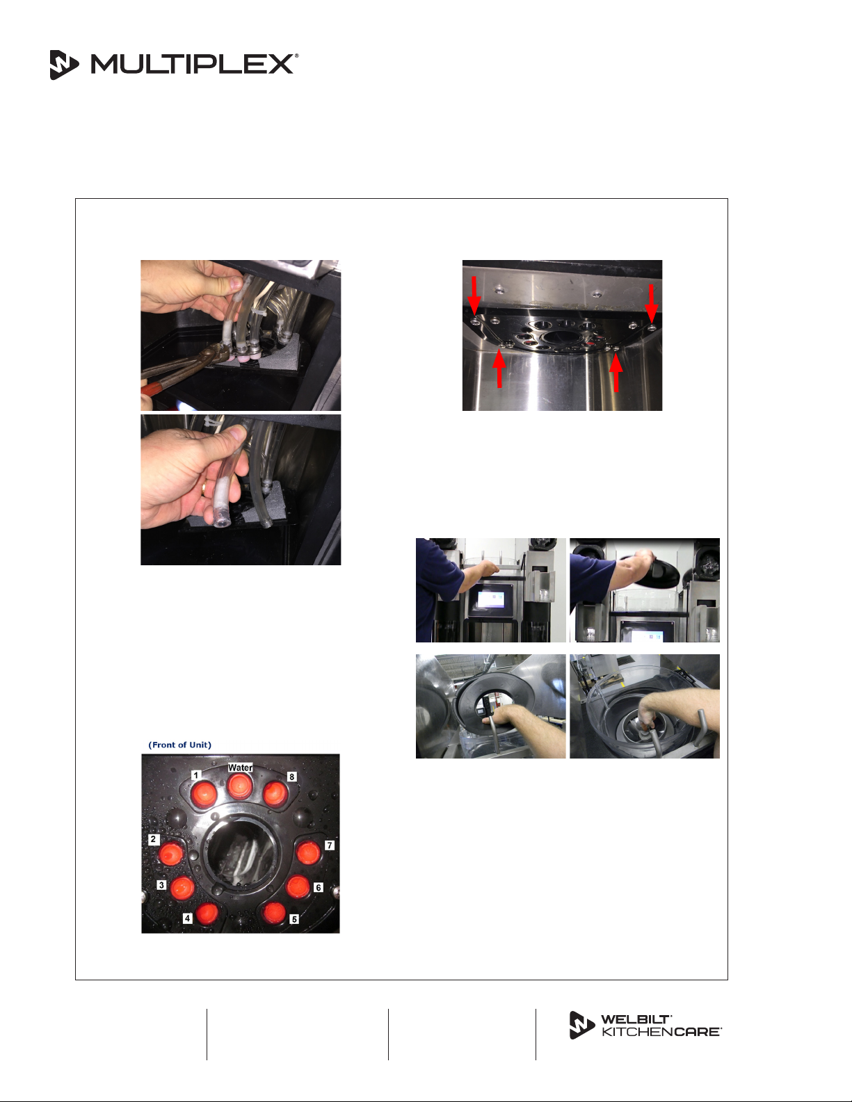
32. Locate the drain tube within upper frame of the unit.
Beginning at the discharge of each drain
outlet squeeze the tubing from front to back
dislodging any buildup within the tubing.
33. Snake each drain with a 3 ft piece of ¼”I.D. x ⁄“
O.D. flexible clear tubing. Verify water is draining
sufficiently out of the blend chambers.
34. Check unit to make sure it is level from front to back
and side to side.
35. Repeat Step 31 until each drain line runs clear.
36. Return and secure the upper right side panel.
37. Return the unit to its serving station and
connect water line, CO line, drain and plug into
the power supply.
38. Power the unit on using the ON/OFF switch
located on the upper left side of the unit next to
the USB port.
39. From the easyToUCH screen select the hands
icon. Then select the Zone 2 icon and follow the
instructions to complete the weekly cleaning.
NOTE: The manager will need to be informed that
the weekly cleaner timer was reset following the
Zone 2 cleaning. To get the weekly cleaning back
to the stores normal cleaning schedule they will
need to perform the weekly cleaning on the normal
scheduled day.
NOTE: Water and CO pressure settings can be
verified and adjusted during the Zone 2 cleaning.
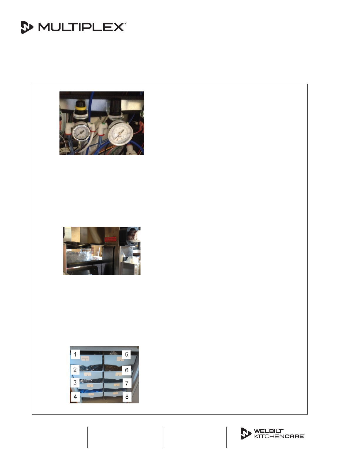
40. If not completed in the previous step verify the
water and CO pressure regulators are set to 35
psi dynamic.
The regulators are located on the upper left side
of the unit.
NOTE: To achieve a dynamic pressure setting for the
water a water solenoid must be activated. To achieve
a dynamic pressure setting for the CO one of the
product solenoids must be activated.
NOTE: Follow the next steps from the easyToUCH
screen to activate a water solenoid and/or a product
solenoid:
• Select the Manager Menu Icon
• Select "A" for the password
• Select the green check
• Arrow down and Select Service
• Select "A" for the password
• Select the green check
• Select OUTPUTS
• Activate any of the eight (8) flavor
solenoids and adjust the CO regulator to
35 psi dynamic
• Turn OFF selected FLAVOR SOLENOID
• Arrow Down then select either the
WATER, LEFT RINSE, or RIGHT RINSE
and adjust the water regulator to 35 psi
dynamic
• Turn OFF selected water dispense option
• Arrow back three (3) times to return to
the main easyToUCH screen.
NOTE: To increase the pressure lift the knob at the
top of the regulator and turn clockwise. To decrease
the pressure lift the knob at the top and turn
counter clockwise.
Multiplex
2100 Future Drive
Sellersburg, IN 47172
Phone: 844-724-2273
Fax: 920-683-7592 Page 9 of 13
2020 Tune Up, continued

Once the 35 psi dynamic setting has been achieved
push the knob back to the downward position and
turn off the water solenoid and/or the product
solenoid.
41. Return and secure the upper left side panel.
42. Return and secure the upper rear panel.
43. Point out the service label to the manager and
inform him or her that all service requests need
to be placed by calling the number on the label.
The service label should be adhered to inside or
outside of the right side cup holder.
44. Retrieve the product from the walk in cooler
and return it to the assigned slot position within
the BIC unit.
NOTE: Verify flavor slot assignments are in
accordance with McDonald’s corporate. If the
product assignments are not in accordance they
must be reassigned.
Strawberry
Banana
Mocha
Caramel
Not
Assigned
Slushy
Seasonal
Mango
Pineapple
Yogurt
If reassignment is required follow the next steps
from the easyToUCH screen;
• Select the Manager Menu Icon
• Select "A" for the password
• Select the green check
• Select the Configure Slots Icon
• Select Slot Flavor
• Select the slot requiring reassignment
• Select Unassign Flavor and then select
the Green Check
• Select the newly Unassigned Slot and
select the correct flavor assignment
• Select the Return Arrow three (3) times
to return to the main easyToUCH screen
• Select product Inventory Icon
• Select the reassigned flavor and follow
the steps for replacing a product bag.
NOTE: Be sure to prime enough product so that no
air is present in the line.
• Follow the same procedures for each
reassigned product.
45. Fill the ice bin with ice.
46. Allow cabinet and nozzle temperatures to drop
below 40°F. Cabinet temperature will need to be
40°F or below before beginning Step 47.
47. Perform a calibration following the next steps
from the easyToUCH screen;
• Select the Manager Menu Icon
• Select "A" for the password
• Select the green check
• Select CONFIGURE SLOTS
• Select CALIBRATE FLAVOR
• Select flavor in slot 1 and follow the on
screen calibration instructions.
• Continue calibrating each flavor, water,
and ice.
Multiplex
2100 Future Drive
Sellersburg, IN 47172
Phone: 844-724-2273
Fax: 920-683-7592 Page 10 of 13
2020 Tune Up, continued

48. Follow the next steps from the easyToUCH
screen to reset the LAST MAINTENANCE DATE;
• Select the MANAGERS MENU
• Select "A" for the password
• Select the green check
• Select the Down Arrow and select
SERVICE
• Select "A" for the password
• Select the green check
• Arrow down and select PLANNED
MAINTENANCE
• Select MIXER MAINTENANCE
PERFORMED
• Type SILENCE
• Select the green check
• Confirm screen displays "Confirmation
Blender(s) Maintenance Done"
• Select the green check
• Arrow back three (3) times
49. From the easyToUCH screen select the
MANAGERS MENU;
• Select "A" for the password
• Select the green check
• Arrow down two (2) times
• Note the UI Version
• Note the SRB Version
• Note the Left and Right Mixer Version
• Note the File
• Note the Menu Connect version
50. From the easy Touch screen select the Manager
Menu Icon;
• Select "A" for the password
• Select the green check
• Arrow down three (3) times
• Under the DRINKS SINCE INSTALLATION
heading note the Left Mixer count, Total
Count, and Right Mixer Count.
51. Confirm the “CONFIGURE YOGURT SMALL
DISPENSE” is set to zero (0) from the easyToUCH
screen;
• Select the Managers Menu
• Select "A" for the password
• Select the green check
• Arrow down one (1) time
• Select SERVICE
• Select "A" for the password
• Select the green check
• Arrow down two (2) times
• Select CONFIGURE YOGURT SMALL
DISPENSE
• Confirm SLOT NUMBER is zero (0).
• If SLOT NUMBER is not zero (0), select
the box to the left> Enter 0> Select the
green check> Arrow back twice> and
Save if prompted.
52. Confirm “PLUNGE SPEED” is set at 15 and “CUP
OFFSET” is set at 2.0 from the easyToUCH screen;
• Select the Managers menu
• Select "A" for the password
• Select the green check
• Arrow down once
• Select SERVICE
• Select "A" for the password
• Select the green check
• Select Options
• Arrow down twice
• Confirm the box to the left of PLUNGE
SPEED is set to fifteen (15), select box
and enter 15 if required> Select the
green check to confirm>
• Confirm the box to the left of CUP
OFFSET is set to 2.0, if required select the
box and enter two (2), zero (0), this will
change the setting to 2.0
• Select the green check
• Arrow back three (3) times
• Select Save when prompted
53. With the manager present make sample drinks
of each size.
54. Confirm operation of all functions.
55. Provide the removed parts to the manager.
Multiplex
2100 Future Drive
Sellersburg, IN 47172
Phone: 844-724-2273
Fax: 920-683-7592 Page 11 of 13
2020 Tune Up, continued

56. Complete the Tune Up Checklist and fax
immediately to fax number: 920-683-7592 or
very important the completed checklist is faxed
in directly from the store and immediately
following sign off by the manager. Immediate
receipt of the checklist allows for daily tracking
of the Tune Up program and helps ensure we
meet the targeted completion date.
57. Maintain a copy of the Tune Up Checklist
to be submitted along with the invoice for
payment. Submit claim for service work through
MultiplexBeverage.com Claims Processing
System (CPS) www.multiplexbeverage.com/
Service/Warranty#Claims-Processing-System
Multiplex
2100 Future Drive
Sellersburg, IN 47172
Phone: 844-724-2273
Fax: 920-683-7592 Page 12 of 13
2020 Tune Up, continued

Store Address: Store Phone #:
Store Number:
Serial Number: Model:
Technician Signature: Date:
Technician Printed Name: Time In:
Service Agent: Time Out:
By signing this you agree that the Preventive Maintenance has been done completely and is satisfactory.
Store Manager Signature: Date:
Store Manager Printed Name: Time:
Pour beverage drain cleaner down the left blend chamber drain, dispense
area drain and the right blend chamber drain? Step 4 page 3.
Replaced the LMSValves? Step 5 - Step 10 page 5.
Remove the ice bin. Step 13 page 6.
Pour beverage drain cleaner down the ice condensate bowl drain opening?
Step 13 page 6.
Replaced the shaver blade. Step 14 page 6.
Remove the ice shaver gasket from the ice bin and/or the top of the
dispense area cover? Clean the surface areas? Step 15 page 6
Wash, rinse and sanitize the ice bin? Step 16 page 6.
Replace the shaver gasket? Step 17 page 6.
Replace the shaver motor? Step 19 - Step 23 page 7.
Replace the COandWater supply line O-rings? Step 25 & 26 on page 8.
Clean the condenser coil? Step 27 page 8.
Clean the condensate pan? Step 28 page 8.
Clean the condensate drain line? Step 29 page 8.
Pour hot water down drain openings of the ice bin, right blend chamber,
dispense area, and left blend chamber? Step 31 page 8.
Workthedrainsbyhandsqueezingoutanybuildup?Step32- 33 on page9.
Review the serial number to determine the date of manufacture. Record
the serial number on the checklist?
Return and secure upper right side panel? 36 on page 9
Return unit to its service station, connect water, CO, drain, and power
cord? Step 37 page 9.
Power the unit on? Step 38 page 9.
Complete the Zone 2 cleaning? Step 39 page 9.
Set the water pressure regulator to 35 psi dynamic? Step 40 page 9.
Set the COpressure regulator to 35 psi dynamic? Step 40 page 9.
Return and secure upper left side panel? Step 41 page 10.
Return and secure the upper rear panel? Step 42 page 10.
Adhere the service label to the inside or outside of the right side cup
holder? Step 43 page 10.
Inform manager that all service requests need to be called into the phone
number on the label? Step 43 page 10.
Verify and assign avor slot assignments in accordance to McDonald’s
Corporate? Step 44 page 10.
Retrieve product from the walk in cooler and return to the BIC refrigerated
cabinet? Step 44 page 10.
Perform calibration for all avors, water and ice? Step 47 page 10.
Reset“LAST MAINTENANCE DATE”? Step 48 page 11.
Record rmware and recipe versions? Step 49 page 11.
UI SWVERSION____________ SRB SWVERSION __________
LEFT MIXER SW____________ RIGHT MIXER SW __________
FILE __________________ MENU CONNECT __________
Record“DRINKS SINCE INSTALLATION”? Step 50 page 11.
LEFT MIXER COUNT _________ TOTAL COUNT ____________
RIGHT MIXER COUNT_________
Conrm that“CONFIGUREYOGURT SMALL DISPENSE”is set to zero (0).
Step 51 page 11.
Conrm“PLUNGE SPEED”is set to 15 and“CUP OFFSET”is set to 2.0.
Step 52 page 11.
Make sample drinks of all sizes? Manager to be present. Step 53 page 11.
Conrm operations of all functions? Step 54 page 11.
Please list any additional parts used during the Tune Up that were not
included in theTune Up kit. ___________________________
___________________________________________
Provide the manager with the used parts? Step 55 page 11.
Verify operation of unit with Manager
Note any manager concerns:
Fax the completed checklist from the site to 920-683-7592 or email
to rise.callcenter@welbilt.com.
Submit claim for service work through MultiplexBeverage.com CPS
(Claims Processing System) www.multiplexbeverage.com/Service/
Warranty#Claims-Processing-System
Multiplex
2100 Future Drive
Sellersburg, IN 47172
Phone: 844-724-2273
Fax: 920-683-7592 Page 13 of 13
2020 Tune Up Checklist
This manual suits for next models
5
Table of contents
Other Multiplex Beverage Dispenser manuals
Popular Beverage Dispenser manuals by other brands

Primo Water
Primo Water hTRIO B380K quick start guide

SaniServ
SaniServ WB Series Operation manual

Bunn
Bunn CDS-2 OPERATING & SERVICE MANUAL

Grindmaster
Grindmaster Crathco G-Cool Single C-1S Brochure & specs

Cornelius
Cornelius ENDURO-150 6 VALVE Operator's manual

Marco
Marco Ecoboiler UC4L 2.4kW Instructions for use