Muncie OMNI-SYSTEM PLUS Quick guide

OMNI-SYSTEM PLUS
SNOW & ICE DIVISION
OPERATION AND
CONFIGURATION MANUAL

PAGE 1 OMNI-SYSTEM

SNOW & ICE DIVISION PAGE 2
TABLE OF CONTENTS
Controller Specications and Features.......................................................................................4
Controller Navigation/Button Assignments................................................................................ 5
Body Selection and Diagnostics Connection............................................................................. 6
Main Operating Screen—Standard Spreader Body....................................................................7
Main Operating Screen—Anti-ice/Tow Plow ...............................................................................8
Main Operating Screen—Directional Body/Sprayer................................................................... 9
Main Operating Screen—External Equipment Body/Uncontrolled Body............................... 10
Operator Adjustments/Datalogging Screens............................................................................ 11
Accessing and Navigating Conguration Menu/Firmware Updates....................................... 12
System Proles............................................................................................................................13
Wi-Fi conguration......................................................................................................................14
Datalogging Setup.......................................................................................................................15
Global Spreader Settings.......................................................................................................16-18
Granular Rate/Liquid Rate Setpoints.........................................................................................19
Conguration Per Body Selection ........................................................................................20-25
Cylinder Congurations (Plow and Hoist) ...........................................................................26-27
System Alerts...............................................................................................................................28
Notes.............................................................................................................................................29

PAGE 3 OMNI-SYSTEM

SNOW & ICE DIVISION PAGE 4
FEATURES & SPECIFICATIONS
Controller Specications
• Color Touchscreen Display
• Uses LED Back Lighting
• Tactile Switch Controls
• Built-in Audible Alarm
• Ergonomic Control Design
• GPS based Data-Logging
• Wi-Fi Connectivity
• CANBUS Platform
• Air & Road Temperature Sensor Ready
Controller Features
• Congurable Error Status Indicators
• Open & Short Circuit Protection and Alerts
• Current Compensated, Pulse Width Modulated Outputs
• System Sources Current to Valve Coils
• Upgradeable Software
• Data Downloading through Wi-Fi & USB Drive
• Real-time Wi-Fi Support Line
• AVL System Ready
• Ground Speed Orientation
• Programmable Body Congurations
• Open/Closed Loop Spreader & Liquid Operation
• Expandable I/O

PAGE 5 OMNI-SYSTEM
CONTROLLER OPERATION
CONTROLLER NAVIGATION:
Cycle Screens: Depress the Auger or Spinner
to cycle screens.
Adjustments: Tap the appropriate touch screen
button to change settings. Hydraulic performance
settings can be adjusted in the conguration menu.
Operation: Use the appropriate buttons and rotary
knobs to control the spreader operation.
BUTTON ASSIGNMENTS:
Spreader: Press to initiate the spreader system.
Blast: Press to “Blast” or increase the granular rate to a
congurable set point for an adjustable time.
Pause: Press to pause or un-pause all spreader
operations.
Blast
Cycle Screen
Back
Spreader Pause
Cycle Screen
Forward

SNOW & ICE DIVISION PAGE 6
Body Selection & Diagnostic
Connection:
This following screen should be referenced
before any operation to ensure the “Body”
selection type is correct for the given body
that is currently being operated. Selecting the
wrong body type could result in unintended
machine operation.
Body Selection – Depress the Body Selection
button to sequence through dierent body
conguration. Note: Available body type discussed
later in the document and are precongured by
Muncie Technicians before system ships. Alternate
body congurations can be added by contacting
the Muncie Power Products Snow and Ice team.
Diagnostic Connection – This feature allows
the user to connect to Muncie for diagnostic
purposes. Simply connect to a Wi-Fi network and
press the Start button to connect to Muncie for
Diagnostic help.
Remote Connection Status – Displays the current
state of the wireless connectivity (Muncie Use Only).
CONTROLLER OPERATION

PAGE 7 OMNI-SYSTEM
CONTROLLER OPERATION
Main Operating Screen – Standard
Spreader Body:
Air Temp/Road Temp – Displays air and
road temperatures. Temperatures will only
display if IR temperature sensor is installed.
Trip Totals – Displays the material and liquid
totals per trip. Simply tap to reset. Keep in
mind that resetting these totals doesn’t reset
the spreader datalog.
Joystick Mode – Displays the current piece
of equipment the joystick is controlling.
Wi-Fi Strength – Displays the Wi-Fi
signal strength.
System Pressures/Oil Temperature –
Toggle this selection to alternate between
system pressures and oil temperature.
Message Bar – Displays error messages.
Spinner Rate – Displays the spinner rate as
a percent or lane coverage.
Pre-Wet Rate – Displays the pre-wet rate.
Product Type – Displays the material being
spread. Tap to change products available.
Auger Rate – Displays the auger rate. In
manual mode, the setting is displayed as
a percentage. In auto mode the rate is
displayed as Lbs/Mile. Keep in mind that this
value will remain constant, but the material
discharged will vary per vehicle speed to
maintain a constant output per mile.
Mode – Displays the mode of operation.
Toggle button to change between Auto
and Manual.
Hot Buttons – Buttons can be congured
on the touchscreen for additional system
functionality.
Time – Displays the current time.
Message
Bar
Time
Hot
Buttons
Vehicle
Speed
Body
Type
Joystick Wi-FiSystem
Pressure/
Oil
Temps
Mode
Product

SNOW & ICE DIVISION PAGE 8
MAIN OPERATING SCREENS
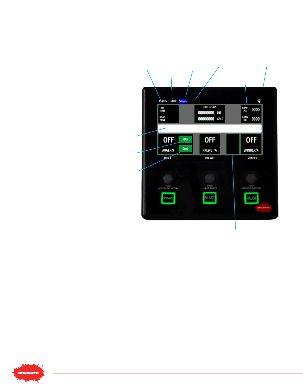
Main Operating Screen – Anti Ice:
Air Temp/Road Temp – Displays air and road
temperatures. Temperatures will only display if IR
temperature sensor is installed.
Joystick Mode – Displays the current piece of
equipment the joystick is controlling.
System Pressures/Oil Temperature –
Toggle this selection to alternate between
system pressures and oil temperature.
Message Bar – Displays error messages.
Liquid Rate – Displays the liquid rate. Use the auger
rate knob to control the speed of the liquid output.
Mode – Displays the mode of operation. Toggle
button to change between Auto and Manual.
Boom Controls – Up to 3 booms can be congured with
the system. Booms can either be controlled with on screen
touch buttons or switch controls. Press appropriate boom
controls to actuate. When a boom is actuated, the button
will latch orange to indicate that it is “on”.
Main Operating Screen – Tow Plow:
Air Temp / Road Temp – Displays air and road
temperatures. Temperatures will only display if IR
temperature sensor is installed.
Joystick Mode – Displays the current piece of
equipment the joystick is controlling.
System Pressures / Oil Temperature – Toggle this
selection to alternate between system pressures
and oil temperature.
Message Bar – Displays error messages.
Auger Rate – Displays the auger rate. In manual
mode, the setting is displayed as a percentage. In
auto mode the rate is displayed as Lbs/Mile.
Auger #2 Rate – Displays the auger rate for the tow
plow. In manual mode, the setting is displayed as a
percentage. In auto mode the rate is displayed as
Lbs/Mile.
Spinner Rate – Displays the spinner rate as a
percent or lane coverage.
Mode – Displays the mode of operation. Toggle
button to change between Auto and Manual.
Joystick
Mode Not
Shown
Liquid
Rate
Spreader
Mode
Wi-Fi
Air Temp/
Road
Temp
Boom
Controls
Message
Bar

PAGE 9 OMNI-SYSTEM
MAIN OPERATING SCREENS
Main Operating Screen –
Directional Body:
Air Temp/Road Temp – Displays air and road
temperatures. Temperatures will only display if IR
temperature sensor is installed.
Trip Totals – Displays the material and liquid
totals per trip. Simply tap to reset. Keep in
mind that resetting these totals doesn’t reset the
spreader datalog.
Joystick Mode – Displays the current piece of
equipment the joystick is controlling.
System Pressures/Oil Temperature –
Toggle this selection to alternate between
system pressures and oil temperature.
Message Bar – Displays error messages.
Product Type – Displays the material
being spread. Tap to change products.
Liquid Rate – Displays the liquid rate. Use the auger
rate knob to control the speed of the liquid output.
Mode – Displays the mode of operation. Toggle
button to change between Auto and Manual
Main Operating Screen – Spray Body:
Trip Totals – Displays the material and liquid
total per trip. Simply tap to reset. Keep in mind
that resetting these totals doesn’t reset the
spreader dialog.
System Pressures/Oil Temperature – Toggle this
selection to alternate between system pressures
and oil temperature.
Message Bar – Displays error messages.
Liquid Rate – Displays the liquid rate
Mode – Displays the mod of operation. Toggle
button to change between Auto and Manual.
Boom Controls – Up to 3 booms can be congured with
the system. Booms can either be controlled with on screen
touch buttons or switch controls. Press appropriate boom
controls to actuate. When a boom is actuated, the button
will latch orange to indicate that it is “On”.
Mode Body
Type
Joystick
Mode
Not Shown
System
Pressure/
Oil Temps
Lane
Adjustments
Liquid
Rates

SNOW & ICE DIVISION PAGE 10
MAIN OPERATING SCREENS
Main Operating Screen – External
Equipment Body:
Air Temp/Road Temp – Displays air and road
temperatures. Temperatures will only display if IR
temperature sensor is installed.
Trip Totals – Unused for this mode. The system is
simply turning ow on and o to designated output.
System Pressures/Oil Temperature – Toggle this
selection to alternate between system pressures
and oil temperature.
Message Bar – Displays error messages.
External Equipment – Displays the “O” or “On”
status for the hydraulic ow to External Equipment.
Main Operating Screen –
Uncontrolled Body:
Air Temp/Road Temp – Displays air and road
temperatures. Temperatures will only display if IR
temperature sensor is installed.
Trip Totals – Unused for this mode. No spreader
functions available in this mode.
System Pressures/Oil Temperature – Toggle this
selection to alternate between system pressures
and oil temperature.
Message Bar – Displays error messages.

PAGE 11 OMNI-SYSTEM
OPERATOR SCREEN ADJUSTMENTS
Day/Night - The controller has two congurable
brightness settings for day and night modes.
Select the mode and adjust the screen and button
brightness as desired. Controller will automatically
change from Day/Night mode at sunrise/sunset time
each time. Pressing this button will swap modes
and can be used to override this setting.
Screen Brightness – Select to adjust the screen
brightness.
Button Brightness – Select to adjust the button
brightness.
Volume – Select to adjust the volume of the controller.
Driver – Toggle to select the pre-congured operator.
Route – Toggle to select the pre-congured route.
Body Selected – Toggle to select an alternate
pre-congured body modes. Additional body
congurations can be added by contacting the
Muncie Power Products Snow and Ice Team.
Enter Cong Menu – Select this setting to enter the
conguration menu. Reference page 5 to access the
conguration menu and make system adjustments.
This menu is password protected to limit access to
unauthorized personnel.
Granular Totals – Displays the total granular materials
by product, discharged since log last cleared.
Totals – Displays the total amount of deicing and
Pre-wetting products discharged since last log cleared.
Truck ID – Displays the pre-congured user
ID, which is utilized for eet-wide data logging
purposes.
Averages – Displays the average discharge rates
of de-icing products and average vehicle speed.
System – Shows real-time status of vehicle speed,
liquid tank level, current runtime and total runtime.
Diagnostics – Shows real-time status of hydraulic
pressures, oil temperature (if applicable), and oil
level (if applicable).
MAIN OPERATING ADJUSTMENTS
Remote Connection Status – Displays the current state of
the wireless connectivity (Muncie Use Only).
Diagnostic Connection – This feature allows the user to
connect to Muncie for diagnostic purposes. Simply connect
to a Wi-Fi network and press the Start button to connect to
Muncie for Diagnostic help.

SNOW & ICE DIVISION PAGE 12
OPERATOR SCREEN ADJUSTMENTS
Accessing Conguration Menu:
This menu is passcode protected to limit access
to non-authorized personnel. It is recommended
to change the passcode from the default value
to limit access and prevent unintentional system
adjustments.
Follow the steps below to enter the conguration menu:
1. Using the touchscreen, press the “ENTER
CONFIG” BUTTON. This should prompt a
keyboard to appear.
2. Using the onscreen keyboard, enter the
passcode and press the return button at the
bottom right of the screen.
(Default Passcode = 1)
Conguration Menu – Navigation:
Screen Navigation – Depress the auger and
spinner knobs to cycle through the conguration
menu screens.
Quick Access Bar – Utilize the quick access bar on
the left side of the screen to directly access certain
conguration screens.
Conguration Menu – System Information:
Truck ID – To change, select the truck ID box. The
truck ID allows the user to keep the datalog information
separate between the trucks.
Flash Drive Status – Displays the status of the ash
drive. To connect, simply insert a USB ash drive in the
USB port. The ash drive should auto connect. If not,
press the “CONNECT USB” button. To disconnect,
press the “DISCONNECT USB” button.
Firmware Update: if instructed by Muncie, connect
ash drive with the appropriate rmware les and press
the “UPDATE FIRMWARE” button.
System Sync: In the event a new module is replaced in
the system, press the “system sync” button to manually
resend the appropriate settings to the new module.
System Versions: Displays the current version of
rmware installed on the system (Muncie Use Only).
CONFIGURATION MENU

PAGE 13 OMNI-SYSTEM
CONFIGURATION MENU
Conguration Menu – System Prole:
Truck Prole Number – The prole contains all of
the unique calibration settings, button mapping, and
I/O congurations of the system. The user is able
to download this le (system prole) and load to
identical systems within a eet to mirror settings.
Load Prole – The “LOAD PROFILE” button allows
the user to transfer the system prole from the ash
drive to the spreader controller (i.e. upload).
Save Prole – The “SAVE PROFILE” button allows
the user to transfer the system prole from the
controller to the ash drive. (i.e. download)
Flash Drive Status – Displays the status of the ash
drive. To connect, simply insert a USB ash drive in
the USB port. The ash drive should auto connect.
If not, press the “CONNECT USB” button. To
disconnect, press the “DISCONNECT USB” button.

SNOW & ICE DIVISION PAGE 14
CONFIGURATION MENU
Conguration Menu – Connecting to Wi-Fi:
View Networks/View Cong – Toggle this button
to switch between connected Wi-Fi networks vs.
available networks.
Available Networks – To connect to an available
network, click on the view networks button and
select the preferred Wi-Fi network and enter the
appropriate credentials.
Manually Add Network – If the network is
unavailable or hidden, the user may manually
connect.
1. Click [Add Network] on the Wi-Fi conguration
screen and populate the appropriate elds.
2. If network is hidden, select this option on the
network credentials page.
3. Push “UPDATE” to Save Entry and Connect.
Connected Networks – On the View Cong page
under the “ADD Network” button the current list of
connected networks will be displayed.
Remove Network – To remove a network click
“DELETE” button next to the network you wish
to delete.

PAGE 15 OMNI-SYSTEM
Conguration Menu – Datalogging:
Flash Drive Status – Displays the status of the
ash drive. To connect, simply insert a USB ash
drive in the USB port. The ash drive should auto
connect. If not, press the “Connect USB” button. To
disconnect, press “Disconnect USB button.
Transfer Logs to USB – Press the “TRANSFER LOGS
TO USB” to download datalog les to ash drive.
Clear Logs – Press the “CLEAR LOGS” button to
delete the stored datalog les.
Date/Time Synchronization
• Manually Set Date/Time – Press the “Sync to
GPS” button to change it to manually set. This
will allow the “Set DATE/TIME” button to be
used to manually set the time and date.
• Auto Set Date/Time – When set to Sync to
GPS it will automatically get time and date from
GPS receiver.
Time Zone Synchronization – When set to Sync to
GPS the time zone will be found using the onboard
GPS. Pressing this button will change the system to
allow for manual entry of the time zone.
Conguration Menu – Datalogging:
Time Interval – Toggle to set how often the system
records data points. Available settings are 10, 30, 60,
90, and 120 seconds.
Log Clear – The Log clear selection allows the user to
set when the datalog is cleared.
• AUTO – clears the datalog after downloading.
• DAILY – clears the datalog once a day.
• NEVER – allows the controller to continue
recording unless manually cleared through the
conguration menu.
Log E-Mail – Insert the email address to auto send/
email log les. Keep in mind the controller will need to
be connected to a Wi-Fi signal to send these les.
The datalog les are sent out 10 times a day in two hour
intervals. Any log les with the same email address will
be sent at the same time. Files will come from noreply@
munciepower.com This is an unmonitored address, so
do not send email replies to it.
To download the les from an email, right click the
attachment and select the “save as” option and
save the le to the desired location.
CONFIGURATION MENU
Route ID’s – Press each white box to enter the Route ID.
The correct route ID must be selected in the operations
screen. The datalogs will now show the route ID.
Driver ID’s – Press each white box to enter the operator
initials. The correct operator ID’s will now be selectable from
the operation menu and show in the datalogs.

SNOW & ICE DIVISION PAGE 16
Global Equipment Settings:
Pump Type – Toggle the pump type button to
select gear, piston, or disabled. Disabled is utilized
for piston pumps, but the valve network is not
equipped with an electrically controlled main relief.
Main Relief Press – Select to adjust the Main Relief
Pressure. The system can be set to a maximum of
3,000 PSI. Deadhead the plow angle to observe the
main relief pressure.
Current Pressures – This text indicates the
pump pressure and load sense pressure being
transmitted from the pressure transducers located
at the valve assembly.
Groundspeed Cal:
Option 1 – The ground speed can be set two
dierent methods. First, if the pulses per mile
are know for the chassis, simply input the
valve in the “Groundspeed Cal” box.
Option 2 – Or, drive the truck and maintain
20 MPH while pressing the “Calibrate”
button. This will auto populate the
“Groundspeed Cal” text box.
Groundspeed Warning – Press the button to
enable this feature. This will bring up a pop-up
window that can be used to adjust the groundspeed
warning from 0-60 MPH. When the selected speed
is exceeded a message will display in the message
box informing the driver to slow down.
CONFIGURATION MENU

PAGE 17 OMNI-SYSTEM
Global Equipment Settings:
Air/Road Temp – This text displays the current
state temperature being reported from the air/road
temp sensor.
Road Temp Oset – This adjustment allows the
road temperature to be tuned if the current reading
is slightly inaccurate.
1. To check the accuracy of the road temperature,
insert a cup of ice water under the IR sensor.
The temperature should read approximately
32° F.
2. If the temperature is o, select the text box
to oset the temperature as needed.
* The air temperature cannot be adjusted.
Keep in mind that the air temperature can be
slower to adjust since it is a function of the
sensor housing.
Air Temp Alert – This adjustment allows the
conguration of an alert associated with exceeding
the desired temperature threshold.
Road Temp Alert – This adjustment allows the
conguration of an alert associated with exceeding
the desired temperature threshold.
CONFIGURATION MENU

SNOW & ICE DIVISION PAGE 18
Global Equipment Settings:
Retain Settings – The retain settings button allows
the system to retain the Auger, Liquid, and Spinner
rates through power cycles.
Caution: This will cause the spreader controller
to retain the settings after the controller has been
powered o. Be aware that simply pressing the
“Spreader” button will automatically re-engage the
motors at their previous settings.
Manual Mode Lockout –
Manual mode can be
enabled or disabled by toggling this button. Disabling
manual mode will prevent the operator from accessing
this mode above 7 MPH graying out the option to
switch modes. When under 7 MPH access to the
manual mode to allow material to be ooaded.
0 MPH Spinner –
The 0 MPH spinner feature allows
the spinner operation to halt when the truck comes to
a stop. If the setting is congured for “spinner on” the
spinner will remain spinning regardless of truck speed.
Blast Level – The blast level sets the auger speed
when the blast button is pressed. This is adjustable
from 50-100%.
Blast Duration – The blast duration can be adjusted
from 1-254 seconds. When below 1 second, the
blast duration will display momentary and will only
stay on when the blast button is held. When above
254 seconds, the blast will display “Latch” and will
keep the blast on indenitely.
Take-o Timer – The Take-o Timer is adjustable
from 0.5 seconds. Turning this setting above 0 will
cause the auger to blast material or liquid for the set
increment of time after the truck has accelerated
from a stop.
Global Spreader Settings:
Main Product Name – The Main Product Name
allows the user to change the text for the primary
spreader material. Select box to change.
Lane Width – This calibrates the controller to
the correct lane width for the spinner. This is only
relevant when the directional spinner mode is active.
Directional Mode – When engaged, this allows the
controller to spread material in feet or lanes.
CONFIGURATION MENU

PAGE 19 OMNI-SYSTEM
Granular Setpoints:
Granular Mode – Two operating modes are available:
Setpoint – If “Setpoint Mode” is selected, the
user has the ability to dial in the exact auto
mode settings available to the operator. Up to
six rates are available to pre-congure.
Range – If range is selected, the user has the
ability to set the low and high rates available
for auto mode.
Granular Products:
Product Names – Select the white boxes to change
the alternate product names.
Granular Ratios – If multiple products are used,
setting product ratios will increase the accuracy
of the material spread. For example, if the user
spreads sand as an alternate product, he could
input the material name in the Alt 1 Box. In addition,
he could input the product weight ratio to increase
the accuracy of the material output discharged.
To calculate the ratio: Take a 5 gallon bucket
of the alternate product and divide by a 5
gallon bucket of salt. (52 lbs./45 lbs.) –
1.15 or 115%.
Anti-Ice Control Settings:
Preset Mode – The user can select two types of
Preset Modes:
Set Point Mode – If setpoint is selected, the
user has the ability to dial in the specic settings
available. Up to three anti-ice rates are available
in this mode.
Range Mode: If range is selected, the user has the
ability to set the low and high auto rates. This gives
the operator a range of settings in gallons per mile.
CONFIGURATION MENU
Table of contents
Other Muncie Automobile Accessories manuals