Muscle Beach CMB-2 Installation guide

America’s Premium Exercise Equipment
ASSEMBLY INSTRUCTION MANUAL
CMB-2
Muscle Beach Home Gym
L 8’-0” W 3’-6” H 7’-0”
Revision Date 9-98
Shown at Full Extension
98 PN-OS0027

CMB-2 Muscle Beach Home Gym
1
About the Muscle Beach Home Gym (CMB-2)
Congratulations on your new purchase of the Muscle
Beach Home Gym (CMB-2). This gym is capable of a
variety of different exercises, as well as, smooth and user-
friendly adjustment features. In addition, this gym has been
designed to meet the needs and performance requirements
for a suitable home exercise machine. We hope you are
completely satisfied with this product and wish you many
years of enjoyment.
Muscle BeachEquipment
Every Muscle Beach product has been built to precise
quality standards and has been carefully packaged to ensure
that damage will not occur during shipment. The limited
lifetime warranty and signature indicating final inspection
which was conducted by our line foreman, is an expression
of our confidence in the completeness, the materials, and
workmanship of this product.
Warranty
SEE WARRANTY REGISTRATION CARD
Registration Card
To avoid unnecessary delays in warranty parts and to
insure that a permanent record of your purchase is on file
with our factory, be sure to complete the warranty
registration card and send it to Task Industries today.
Safety Information
1) Familiarize yourself and others with the proper operation
and workout recommendations for each piece of Muscle
Beach equipment prior to use.
2) Consult with your physician before beginning any
exercise program.
3) Use proper discretion when children are present.
4) Frayed or worn cables can be dangerous and may cause
injury. Periodically check these cables for any indication of
wear.
5) Inspect machine for any sign of parts or hardware
becoming loose.
6) Keep hands and limbs clear from weight stack and all
other moving parts.
Maintenance Information
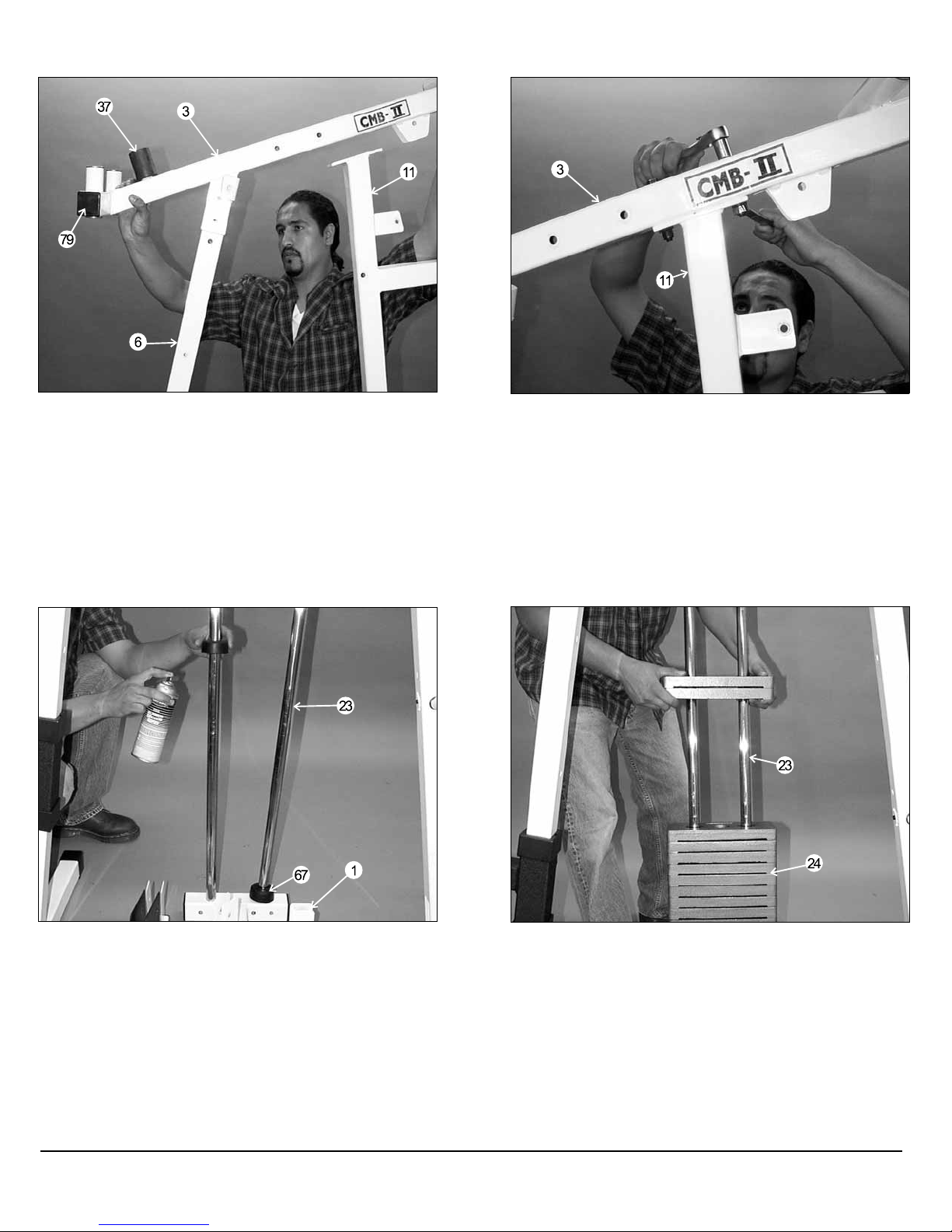
1) Lubrication of all moving parts is essential to the longevity
and optimal performance of your Muscle Beach Home Gym.
Initial lubrication of some parts of your gym have been done
at the factory, but the weight stack guide rods must be
lubricated at the time of assembly. We recommend a clear
aerosol, silicone or Teflon spray.
Note: Do not use oil based lubricants as they will attract
dust,dirt and grime, and will eventually gum up and erode
bushings and sealed bearings.
2) All pulleys and bushings should be checked regularly for
signs of wear.
3) Check and adjust tension on cables periodically as it will
maintain proper anatomical fusnction.
4) Periodically check all moving parts, upholstery and grips
for wear. If replacement is necessary, please contact your
local Muscle Beach retailer or call our Customer Service
Department.
5) As needed, upholstery may be cleaned with a mild
solution of soap and water. Regular use of a vinyl treatment
will add to the life and appearance of your upholstery.
6) All chrome plated surfaces should be cleaned regularly to
prolong the life and luster of the finish. Wipe machine down
with a damp cloth and dry thoroughly each day. At least
once a week your chrome equipment should be polished
with a commercial grade or automotive type chrome polish.
Tool Requirements
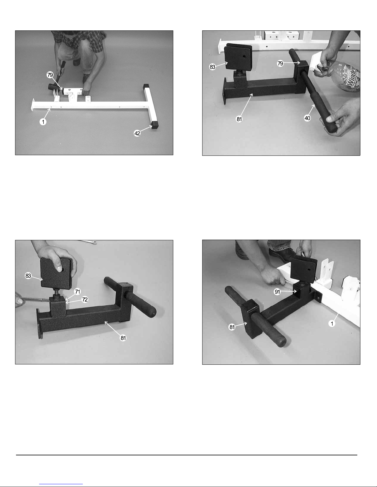
1) Two 3/4” Open-end wrenches
2) Two 9/16” Open-end wrenches
3) One rubber mallet hammer
4) Windex or household glasscleaner
5) One can Silicone Spray/ Teflon Spray Lubricant
6) Snap ring pliers
7) Hex Key 3/16” (Supplied)
7) Windex or household glass cleaner
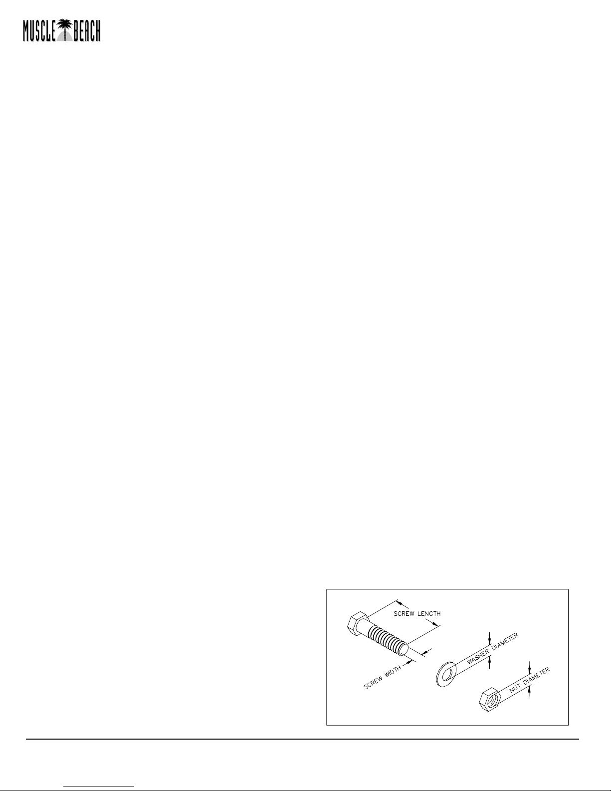
Hardware Measurement Diagram
Introduction

FIG. 1 On a flat surface, lay the Base Frame (#1) down
and insert the two Plastic End Caps 2” Sq. w/groove (#42)
onto the front stabilizer of the Base Frame (#1). Next, insert
two Plastic Insert Caps 2” Sq. (#79) into the Base Frame (#1)
as illustrated above.
FIG. 2 Slide a Hard Grip .875 X 8 (#40) over each end of the
tube on the Low Row Foot Support (#81), This Hard Grip .875
X 8 (#40) fits very tightly onto the Low Row Foot Support (#81)
and it may be necessary to use windex or a household glass
cleaner (as illustrated) to complete this procedure. Next, insert
one Plastic Insert Cap 2” Sq. (#79) into the tube-end of the Low
Row Foot Support (#81).
FIG. 3 Install the Low Row Swivel Pulley Bracket (#83)
into the receptacle on the Low Row Foot Support (#81) and
secure it using one Flat Washer SAE 1/2 (#72) and one Nylon
Insert Jam Lock Nut 1/2-13 (#71). Note: It is recommend that
the axle on the Low Row Swivel Pulley Bracket (#83) be
lubricated with grease prior to assembly.
FIG. 4 Attach the Low Row Foot Support (#81) to the
Base Frame (#1) and secure it using two Hex Head Cap
Screws 3/8-16 X 2 3/4 (#55), four Flat Washers SAE 3/8 (#73)
and two Nylon Insert Jam Lock Nuts 3/8-16 (#69). Next insert
two Plastic Insert Caps 2” X 3” (#91) into the pulley bracket
housing on the Low Row Foot Support (#81).
Owners’ Manual: Assembly Instructions
CMB-2 Muscle Beach Home Gym 2

FIG. 5 Attach the Rear Upright (#6) to the Base Frame
(#1) and secure it using two Hex Head Cap Screws 3/8-16 X 3
(#61), four Flat Washers SAE 3/8 (#73) and two Nylon Insert
Lock Nuts 3/8-16 (#70). Note: Do not tighten this hardware
assembly at this time. Next, insert two Plastic End Caps 2” Sq.
w/groove (#42) into the Rear Upright (#6), as shown above.
FIG. 6 Slide the Pec Dec Adj Seat Tube (#7) onto the
Rear Upright (#6), as shown above. Note: Position the Pec
Dec Adj Seat Tube (#7) with the Push-Pull Pin 1/2 (#89)
facing the same side as the selector holes on the Rear
Upright (#6).
FIG. 7 Attach the Front Upright (#11) to the Base Frame
(#1) and secure it using one Hex Head Cap Screw 3/8-16 X 2
3/4 (#55), two Flat Washers SAE 3/8 (#73) and one Nylon
Insert Jam Lock Nut 3/8-16 (#69). Note: Do not tighten this
hardware assembly at this time.
FIG. 8 Attach the Leg Ext Bench Frame (#8) to the Base
Frame (#1) and Front Upright (#11). Secure the Leg Ext
Bench Frame (#8) to the Base Frame (#1) using one Hex
Head Cap Screw 3/8-16 X 4 1/2 (#88), two Flat Washers SAE
3/8 (#73) and one Nylon Insert Jam Lock Nut 3/8-16 (#69),
Next, secure the Leg Ext Bench Frame (#8) to the Front
Upright (#11) using one Hex Head Cap Screw 3/8-16 X 2 3/4
(#55), two Flat Washers SAE 3/8 (#73) and one Nylon Insert
Jam Lock Nut 3/8-16 (#69). Note: Do not tighten this hardware
assembly at this time.
CMB-2 Muscle Beach Home Gym
3

FIG. 9 Attach the Top Pulley Assembly (#3) onto the Rear
Upright (#6), as shown above, and secure using one Hex
Head Cap Screw 3/8-16 X 2 3/4 (#55), two Flat Washers SAE
3/8 (#73) and one Nylon Insert Jam Lock Nut 3/8-16 (#69).
Next, insert two Plastic Insert Caps 2” Sq. (#79) into the tube-
ends of the Top Pulley Assembly (#3), as shown above.
Next, attach a Rubber Stopper 1 X 2 X 2 1/2 (#37) to the prong
on the Top Pulley Assembly (#3), as shown above.
FIG. 10 Secure the Top Pulley Assembly (#3) to the Front
Upright (#11) using two Hex Head Cap Screws 3/8-16 X 3
(#61), four Flat Washers SAE 3/8 (#73) and two Nylon Insert
Lock Nuts 3/8-16 (#70).
FIG. 11 Insert the two Guide Rods (#23) into the receptacle
of the Base Frame (#1), as shown above. Next, insert two
Rubber Donuts 1 X 2 1/2 (#67) onto each Guide Rod (#23).
Note: Lubricate the Guide Rods (#23) with a silicone or Teflon
lubricant at this time.
FIG. 12 Carefully begin sliding the 10 Lb Weight Plates
(#24) over the Guide Rods (#23), one or two at a time as your
skill permits. Make sure that the 10 Lb Weight Plates (#24) are
installed onto the Guide Rods (#23) in numerical order,
beginning with the number 200 at the bottom, 190 next, and so
on.
Owners’ Manual: Assembly Instructions
CMB-2 Muscle Beach Home Gym 4

FIG. 13 Now slide the Top Plate/ Selector Bar (#12) over
the Guide Rods (#23) allowing it to come to rest on the
completed weight stack.
FIG. 14 Maneuver each of the Guide Rods (#23) into the
holes on the bottom side of the Guide Rod Retainer (#13).
Next, mount the Guide Rod Retainer (#13) along with the two
captive Guide Rods (#23) to the side of the Top Pulley
Assembly (#3) and secure using two Hex Head Cap Screws
3/8-16 X 2 3/4 (#55), four Flat Washers SAE 3/8 (#73) and two
Nylon Insert Jam Lock Nuts 3/8-16 (#69).
FIG. 15 Now position the Press Arm (#2) to the Top Pulley
Assembly (#3), as shown above. Next, press the Pivot Axle 1
X 11 3/4 (#18) through the holes in the Press Arm (#2) and
through the receptacle tube on the Top Pulley Assembly (#3)
using a rubber mallet hammer until it is flush with both sides.
Then insert the Rubber Stopper Cap 2” Sq (#84), as shown on
the Front Upright (#11).Note: It is recommend that you you
grease the Pivot Axle 1 X 11 3/4 prior to assembly.
FIG. 16 At the top edge of each end of the Press Arm (#2)
is a set screw fixture. Secure the Press Arm (#2) using two
Set Screws 3/8-16 X 1/2 (#38). Use the Hex-Key 3/16 (#80)
tool for fastening the Set Screws 3/8-16 X 1/2 (#38). Next,
insert two Plastic Insert Caps 1 X 2 (#77) into the tube-ends of
the Press Arm (#2).
CMB-2 Muscle Beach Home Gym
5

FIG. 17 Insert the Lat Bar Holder (#20) into the tube-end of
the Top Pulley Assembly (#3), as shown above, and secure
using one Hex Head Cap Screw 3/8-16 X 2 1/2 (#56), two Flat
Washers SAE 3/8 (#73) and one Nylon Insert Jam Lock Nut
3/8-16 (#69).
FIG. 18 Insert both Pec Dec Arms (#5) and (#4-Not
Shown) into the receptacle tube on the Top Pulley Assembly
(#3), as shown. Note: It is recommended that the axles on both
Pec Dec Arms (#5) and (#4-Not Shown) be lubricated with
grease prior to the assembly.
FIG. 19 Secure both Pec Dec Arms (#5) and (#4-Not
Shown) to the Top Pulley Assembly (#3) using two Retaining
Snap Rings (#74). If possible, use special snap ring pliers for
this job, as shown above. If not available, carefully work each
Retaining Snap Ring (#74) into the groove, then push down
alternately with a screw driver working the Retaining Snap Ring
(#74) into the groove. Note: Be careful not to distort the
Retaining Snap Ring (#74) or bend it.
FIG. 20 Now attach the Foot Roll Bracket (#51) to the Leg
Ext Arm (#10) and secure it using one Hex Head Cap Screw
1/2-13 X 2 3/4 (#86), two Flat Washers SAE 1/2 (#72) and one
Nylon Insert Jam Lock Nut 3/8-16 (#71). Next, install a Rubber
Bumper 3/8 X 1 1/2 (#60) to the Leg Ext Arm (#10), as shown,
using one Hex Head Cap Screw 3/8-16 X 1 (#59) and one Flat
Washer SAE 3/8 (#73). Note: Do not over-tighten this bolt as
the Foot Roll Bracket (#51) should be allowed to swivel
freely.
Owners’ Manual: Assembly Instructions
CMB-2 Muscle Beach Home Gym 6

FIG. 21 Attach the Leg Ext Arm (#10) to the Leg Ext
Bench Frame (#8), as shown, and secure using one Hex Head
Cap Screw 1/2-13 X 3 1/4 (#53), two Flat Washers SAE 1/2
(#72) and one Nylon Insert Jam Lock Nut 1/2-13 (#71). Be sure
not to over-tighten this hardware assembly as the Leg Ext Arm
(#10) should be allowed to swivel freely. Note: It is
recommended that the Leg Ext Arm (#10) be greased at the
pivot point prior to assembly.
FIG. 22 Insert the Foot Roll Tube 1 X 16 (#21) through the
Foot Roll Bracket (#51). Then insert a Foam Foot Roll 7 X 4
X 1 onto each end of the Foot Roll Tube 1 X 16 (#21). Next,
insert a Plastic Insert Cap 1” Rd (#75) into each end of the
Foot Roll Tube 1 X 16 (#21).
FIG. 23 Attach the Seat Pad (#32) to the Bench Press Adj
Seat Tube (#9). Secure using two Hex Head Cap Screws 3/8-
16 X 1 3/4 (#57) and two Flat Washers SAE 3/8 (#73), as
shown above.
FIG. 24 Insert the Bench Press Adj Seat Tube (#9) into
the receptacle on the Leg Ext Bench Frame (#8), as shown
above. Next, insert two Foam Foot Rolls 7 X 4 X 1 (#30) and
two Plastic Insert Caps 1” Rd (#75) onto the tube-ends of the
Bench Press Adj Seat Tube (#9).Note: Pull the Push-Pull
Pin 1/2” (#23) to allow the Bench Press Adj Seat Tube (#9) to
adjust up and down.
CMB-2 Muscle Beach Home Gym
7

FIG. 25 On the Bench Press Adj Seat Tube (#9) there is a
threaded socket. Secure the Foot Roll Tube 1 X 16 (#21) using
one Set Screw 1/4-20 X 1/4 (#36). Use the supplied Hex-Key
1/8 (#19) tool for securing this Set Screw 1/4-20 X 1/4 (#36).
Next, insert a Plastic Insert Cap 2” Sq. (#79), as shown.
FIG. 26 Now, insert a Foot Roll Tube 1 X 25 (#82) through
the Front Upright (#11), as shown above. Secure the Foot
Roll Tube 1 X 25 (#82) using a Set Screw 3/8-16 X 1/2 (#38).
Use the Hex-Key 3/16 (#80) tool for securing the Set Screw
3/8-16 X 1/2 (#38). Next, insert two Foam Foot Rolls 7 X 4 X 1
(#30) and two Plastic Insert Caps 1” Rd. (#75) into the the Foot
Roll Tube 1 X 25 (#82).
FIG. 27 Attach the Back Pad (#33) for the Bench Press to
the Front Upright (#11) and secure using two Hex Head Cap
Screws 3/8-16 x 2 3/4 (#55) and two Flat Washers SAE 3/8
(#73).
FIG. 28 Attach the Seat Pad (#34) to the Pec Dec Adj Seat
Tube (#7) and secure it using two Hex Head Cap Screws 3/8-
16 X 2 3/4 (#55) and two Flat Washers SAE 3/8 (#73).
Owners’ Manual: Assembly Instructions
CMB-2 Muscle Beach Home Gym 8

FIG. 29 Attach the Pec Dec Back Pad (#33) to the Rear
Upright (#6), as shown, and secure using two Hex Head Cap
Screws 3/8-16 X 2 3/4 (#55) and two Flat Washers SAE 3/8
(#73). Next, insert the two Foam Foot Rolls 1 3/4 X 16 (#29)
onto both of the Pec Dec Arms (#4) and (#5-Not Shown),
Then insert two Plastic Insert Caps 1 3/4 Sq (#78) into the
tube-end of both Pec Dec Arms.Note: Use a windex or
household glass cleaner for easy insertion of the Foam Foot
Rolls (#29).
FIG. 30 Thread one Nylon Insert Jam Lock Nut 1/2-13 (#71)
and one Flat Washer SAE 1/2 (#72) onto the Top Swival
Bracket (#14), as shown in diagram above. Next, attach the
Top Swival Bracket (#14) to the the Guide Rod Retainer
(#13) and secure it using one Nylon Insert Jam Lock Nut 1/2-
13 (#71) and one Flat Washer SAE 1/2 (#72), as shown in
diagram above. Loosely secure the Nylon Insert Jam Lock
Nut 1/2-13 (#71) to allow for adjustment for the cable tension
later in the assembly process.
FIG. 31 Install the Ab Crunch Insert Bracket (#22) and
one Nylon Pulley 4 1/2 Rd. (#48-Not Shown, See Fig. 42) into
the Rear Upright (#6) and secure it using one Hex Head Cap
Screw 3/8-16 X 2 1/2 (#56), two Flat Washers SAE 3/8 (#73)
and one Nylon Insert Jam Lock Nut 3/8-16 (#69).
FIG. 32 Raise the Lat Cable (#44) into place, as shown
above, with the Lat Cable (#44) fitted into the groove of the
Nylon Pulley 4 1/2 Rd. (#48). Secure into place using one Hex
Head Cap Screw 3/8-16 X 1 3/4 (#57), two Flat Washers SAE
(#73) and one Nylon Insert Jam Lock Nut 3/8-16 (#69). Route
the Lat Cable (#44) over the Nylon Pulley 4 1/2 Rd. (#48) and
into the tube of the Top Pulley Assembly (#3). Use Fig. I on
page 15 and Fig. B on page 16 for further detailed illustration
cable routing.
CMB-2 Muscle Beach Home Gym
9

FIG. 33 Route the Lat Cable (#44) through the second
pulley bracket on the Top Pulley Assembly (#3). Then insert
one Nylon Pulley 4 1/2 Rd. (#48) into the pulley bracket on
the Top Pulley Assembly (#3) and secure using one Hex
Head Cap Screw 3/8-16 X 1 3/4 (#57), two Flat Washers SAE
3/8 (#73) and one Nylon Insert Jam Lock Nut 3/8-16 (#69). Use
Fig. I on page 15 and Fig. B on page 16 for further detailed
illustration cable routing.
FIG. 34 Install two Nylon Pulleys 4 1/2 Rd (#48) and two
Cable Retainer Brackets (#17) into the pulley bracket located
on the Press Arm (#2), as shown above. Secure this hardware
assembly using one Hex Head Cap Screw 3/8-16 X 3 1/2
(#54), two Flat Washers SAE 3/8 (#73) and one Nylon Insert
Jam Lock Nut 3/8-16 (#69). Use the exploded view diagram on
page 18 for further illustration of this assembly. Note: Be sure
the Cable Retainer Brackets (#17) are positioned in the
direction shown above. Use Fig. I on page 15 and Fig. B on
page 16 for further detailed illustration cable routing.
FIG. 35 Install one Nylon Pulley 4 1/2 Rd. (#48) onto the
pulley bracket on the Front Upright (#11) and secure it using
one Hex Head Cap Screw 3/8-16 X 1 3/4 (#57), two Flat
Washers SAE 3/8 (#73) and one Nylon Insert Jam Lock Nut
3/8-16 (#69). Route the Lat Cable (#44) through the Nylon
Pulley 4 1/2 Rd. (#48), as shown in Fig. I on page 15 and Fig.
Bon page 16.
FIG. 36 Next, route the Lat Cable (#44) through the Nylon
Pulley 4 1/2 Rd. (#48) on the Press Arm (#2). Use Fig. I on
page 15 and Fig. B on page 16 for further detailed illustration
cable routing.
Owners’ Manual: Assembly Instructions
CMB-2 Muscle Beach Home Gym 10

FIG. 37 Now install a Nylon Pulley 4 1/2 Rd. (#48) and one
Cable Retainer Bracket (#17) onto the Front Upright (#11),
as shown, and secure it using one Hex Head Cap Screw 3/8-
16 X 3 3/4 (#52), two Flat Washers SAE 3/8 (#73) and one
Nylon Insert Jam Lock Nut 3/8-16 (#69). Route the Lat Cable
(#44) over the pulley as shown. Use Fig. I on page 15 and
Fig. B on page 16 for further detailed illustration cable routing.
Note: Be sure the Cable Retainer Bracket (#17) is positioned
as shown above.
FIG. 38 Next, assemble the Double Pulley Plates 1/8 X 2
X 9 (#16) using two Nylon Pulleys 4 1/2 Rd. (#48), two Hex
Head Cap Screws 3/8-16 X 1 3/4 (#57), four Flat Washers
SAE 3/8 (#73) and two Nylon Insert Jam Lock Nuts 3/8-16
(#69). Use the exploded view diagram on page 18 for further
illustration of this assembly. Next, route the Lat Cable (#44)
through the Double Pulley Plates (#16), as shown above.
Note: The four holes on the Double Pulley Plates 1/8 X 2 X 9
(#16) are used to adjust the cable tension once the cable
routing has been complete. Use Fig. I on page 15 for further
detailed illustration cable routing.
FIG. 39 Insert a Nylon Pulley 4 1/2 Rd. (#48) into the Top
Plate Swivel Bracket (#14) and secure it using one Hex Head
Cap Screw 3/8-16 X 1 3/4 (#57), two Flat Washers SAE 3/8
(#73) and one Nylon Insert Jam Lock Nut 3/8-16 (#69). Route
the Lat Cable (#44) through the Top Plate Swivel Bracket
(#14), as shown above. Use Fig. I on page 15 for further
detailed illustration of cable routing.
FIG. 40 Attach the Lat Cable (#44) to the Top Plate/
Selector Bar (#12) and secure it using one Split Bolt 1/2-13 X
1 (#62) and one Split Washer 1/2” (#63). Use Fig. E on page
16 for further illustration of this assembly. Note: Be sure this
hardware assembly is securely fastened.
CMB-2 Muscle Beach Home Gym
11

FIG. 41 Begin the routing of the Pec Dec Cable (#45).
Attach one end of the Pec Dec Cable (#45) to the Pec Dec
Arm Lt (#4), as shown above. Secure the cable using one Hex
Head Cap Screw 3/8-16 X1 (#59), two Flat Washers SAE 3/8
(#73) and one Nylon Insert Jam Lock Nut 3/8-16 (#69). See
Fig. A on page 16 for further clarification of this assembly.
Note: Be sure hardware assembly is securely fastened.
FIG. 42 Attach one Nylon Pulley 4 1/2 Rd (#48) and one
Cable Retainer Bracket (#17) to each side of the Top Pulley
Assembly (#3), as shown above. Secure using two Hex Head
Cap Screws 3/8-16 X 1 3/4 (#57), four Flat Washers SAE 3/8
(#73) and two Nylon Insert Jam Lock Nuts 3/8-16 (#69).
Continue to route the Pec Dec Cable (#45) down to the Offset
Pulley Bracket (#15), as shown in Fig. 43 and Fig. A on page
16.
FIG. 43 Insert two Nylon Pulley 4 1/2 Rd. (#48) into the
Offset Pulley Bracket (#15) and secure using two Hex Head
Cap Screws 3/8-16 X 1 3/4 (#57), four Flat Washers SAE 3/8
(#73) and two Nylon Insert Jam Lock Nuts 3/8-16 (#69). Next
route the Pec Dec Cable (#45) through this bracket, as shown.
Repeat the same procedure in Fig. 41 and Fig. 42 to complete
the routing of the Pec Dec Cable (#45) to the Pec Dec Arm Rt
(#5). Also see Fig. A on page 16 for further clarification of this
assembly.
CMB-2 Muscle Beach Home Gym 12
FIG. 44 Attach the Leg Ext Cable (#43) to the Leg Ext
Arm (#10), as shown above. Secure using one Hex Head Cap
Screw 3/8-16 X 1 (#59), two Flat Washers SAE 3/8 (#73) and
one Nylon Insert Jam Lock Nut 3/8-16 (#69). Refer to Fig. F
on page 16 for further clarification of this assembly.
Owners’ Manual: Assembly Instructions

FIG. 45 Insert a Nylon Pulley 4 1/2 Rd. (#48) into the
pulley bracket on the Base Frame (#1) and secure it using one
Hex Head Cap Screw 3/8-16 X 1 3/4 (#57), two Flat Washer
SAE 3/8 (#73) and one Nylon Insert Jam Lock Nut 3/8-16
(#69). Next, insert the Leg Extension Cable (#43) through the
Front Upright (#11) then through the Nylon Pulley 4 1/2 Rd.
(#48), as shown above. See Fig.I for further clarification.
FIG. 46 Next, lift the loose end of the Leg Extension Cable
(#43) up into the Double Pulley Plates 1/8 X 2 X 9 (#16). See
Fig. I on page 15 for further clarification of this routing.
FIG. 47 Insert a Nylon Pulley 4 1/2 Rd. (#48) into the pulley
bracket on the Base Frame (#1) and secure it using one Hex
Head Cap Screw 3/8-16 X 1 3/4 (#57), two Flat Washers SAE
3/8 (#73) and one Nylon Insert Jam Lock Nut 3/8-16 (#69).
Next, route the Leg Extension Cable (#43) through the Nylon
Pulley 4 1/2 Rd (#48), as shown above. See Fig. I on page 15
for further clarification of this routing.
FIG. 48 Now, lift up the loose end of the Leg Extension
Cable (#43) and route through the Offset Pulley Bracket
(#15), as shown above. See Fig. I on page 15 for further
clarification of this routing.
CMB-2 Muscle Beach Home Gym
13

FIG. 49 Next, route the Leg Extension Cable (#43) down
through the Offset Pulley Bracket (#15), as shown above.
See Fig. I on page 15 for further clarification.
FIG. 50 Finally, route the remainder of the Leg Extension
Cable (#43) through the Nylon Pulley 4 1/2 Rd. (#48) located
on the Rear Upright (#6). Then assemble one Nylon Ball 1 3/4
x 5/16 (#68), one Strap Bracket (#64) and the Abdominal Strap
(#41-Not Shown) onto the cable-end of the Leg Extension
Cable (#43) and secure using one Shoulder Bolt 3/8 X 3/4
(#58) and one Nylon Insert Lock Nut 5/16-18 (#66). Refer to
Fig. C on page 16 for further clarification of this assembly.
FIG. 51 Insert the end of the Short Cable (#46) with the ball
into the Low Row Swivel Pulley Bracket (#83) and secure it
into place with a Nylon Pulley 4 1/2 Rd. (#48). Use the pulley
mounting hardware described in Fig. 47 on page 13 to fasten
the pulley and cable into place. See Fig. I on page 15 for
further clarification.
FIG. 52 Insert a Nylon Pulley 4 1/2 Rd. (#48) and the Short
Cable (#46), as shown above. Use the pulley mounting
hardware described in Fig. 47 on page 13 to fasten the pulley
and cable into place. See Fig. I on page 15 for further
clarification.
CMB-2 Muscle Beach Home Gym 14
Owners’ Manual: Assembly Instructions

Note: Some parts not
shown or cut away
for clarity
Fig. I
See Fig. A
See Fig. B
See
See Fig. C
See Fig. F
See Fig. G,H
See Fig. D See Fig. A
FIG. 53 Finally, connect the other looped end of the Short
Cable (#46) to the empty pulley bracket located on the Base
Frame (#1), as shown above. Refer to Fig. G on page 16 for
proper assembly. Secure this assembly using one Hex Head
Cap Screw 3/8-16 X 1 3/4 (#57), two Flat Washers SAE 3/8
(#73), two Nylon Spacers 3/8 x 3/8 (#47) and one Nylon Insert
Jam Lock Nut 3/8-16 (#69).
Note: This completes the assembly of the CMB-2. It is
recommended that you check and secure all the hardware
assemblies and inspect the complete cable routing of all cables.
CMB-2 Muscle Beach Home Gym
15

Owners’ Manual: Assembly Instructions
CMB-2 Muscle Beach Home Gym 16
FIG. A
FIG. C FIG. D FIG. E
FIG. F FIG. G FIG. H
Note: Some Parts Have Been Cut
Away For Clarity.
FIG. B
Leg Press Configuration

CMB-2 Muscle Beach Home Gym
17
CMB-2 PARTS LIST
Item No. Description Part No. Qty Item No. Description Part No. Qty
1 BASE FRAME CMB2-01-00 1 46 SHORT CABLE CMB2-46-00 1
2 PRESS ARM CMB2-02-00 1 47 NYLON SPACER 3/8 X 3/8 BNH0392 2
3 TOP PULLEY ASSEMBLY CMB2-03-00 1 48 NYLON PULLEY 4 1/2 RD BNH0506 19
4 PEC DEC ARM (LT) CMB2-04-00 1 49 BRONZE BUSHING 1 X 1 1/4 BNH0527 6
5 PEC DEC ARM (RT) CMB2-05-00 1 50 BRONZE BUSHING 1/2 X 5/8 BNH0528 2
6 REAR UPRIGHT CMB2-06-00 1 51 FOOT ROLL BRACKET UP176 1
7 PEC DEC ADJ SEAT TUBE UP133 1 52 HEX HEAD CAP SCREW 3/8-16 X 3 3/4 BNH0281 1
8 LEG EXT BENCH FRAME UP172 1 53 HEX HEAD CAP SCREW 1/2-13 X 3 1/4 BNH0576 1
9 BENCH PRESS ADJ SEAT TUBE UP171 1 54 HEX HEAD CAP SCREW 3/8-16 X 3 1/2 BNH0280 1
10 LEG EXT ARM UP150 1 55 HEX HEAD CAP SCREW 3/8-16 X 2 3/4 BNH0278 14
11 FRONT UPRIGHT CMB2-11-00 1 56 HEX HEAD CAP SCREW 3/8-16 X 2 1/2 BNH0276 2
12 TOP PLATE/ SELECTOR BAR UP003 1 57 HEX HEAD CAP SCREW 3/8-16 X 1 3/4 BNH0274 18
13 GUIDE ROD RETAINER UP169 1 58 SHOULDER BOLT 3/8 X 3/4 BNH0718 2
14 TOP PLATE SWIVAL BRACKET UP127 1 59 HEX HEAD CAP SCREW 3/8-16 X 1 BNH0275 4
15 OFFSET PULLEY BRACKET UP121 2 60 RUBBER BUMPER 3/8 X 1 1/2 BNH0514 1
16 DOUBLE PULLEY PLATE 1/8 X 2 X 9 UP092 2 61 HEX HEAD CAP SCREW 3/8-16 X 3 BNH0282 4
17 CABLE RETAINER BRACKET UP014 6 62 SPLIT BOLT 1/2-13 X 1 BNH0479 1
18 PIVOT AXLE 1 X 11 3/4 UP067 1 63 SPLIT WASHER 1/2 BNH0572 1
19 HEX KEY LONG 1/8" BNH0767 1 64 STRAP BRACKET #20 BNH0562 2
20 LAT BAR HOLDER UP120 1 65 SNAP LINK ZINC BNH0065 2
21 FOOT ROLL TUBE 1 X 16 UP053 2 66 NYLON INSERT LOCK NUT 5/16-18 BNH0215 2
22 AB CRUNCH INSERT BRACKET UP119 1 67 RUBBER DONUT 1 X 2 1/2 BNH0062 2
23 GUIDE ROD UP124 2 68 NYLON BALL 1 3/4 X 5/16 BNH0392 2
24 10 LB. WEIGHT PLATE BNH0561 19 69 NYLON INSERT JAM LOCK NUT 3/8-16 BNH0365 32
25 CHROME LAT BAR 48" UP093 1 70 NYLON INSERT LOCK NUT 3/8-16 BNH0214 4
26 LOW ROW BAR 16" UP094 1 71 NYLON INSERT JAM LOCK NUT 1/2-13 BNH0366 5
27 COIL CHAIN 3/16 X 21 BNH0017 1 72 FLAT WASHER SAE 1/2 BNH0238 7
28 WEIGHT SELECTOR PIN BNH0064 1 73 FLAT WASHER SAE 3/8 BNH0239 80
29 FOAM FOOT ROLL 1 3/4 X 16 BNH0041 2 74 RETAINING SNAP RING BNH0419 2
30 FOAM FOOT ROLL 7 X 4 X 1 BNH0043 6 75 PLASTIC INSERT CAP 1" RD BNH0002 6
31 DECAL- CMB 2 BNH0832 2 76 PLASTIC INSERT CAP 1 1/2 SQ BNH0009 1
32 SEAT PAD UP173 1 77 PLASTIC INSERT CAP 1 X 2 BNH0005 5
33 PEC DEC BACK PAD CMB2-33-00 2 78 PLASTIC INSERT CAP 1 3/4 SQ BNH0053 2
34 SEAT PAD UP122 1 79 PLASTIC INSERT CAP 2" SQ BNH0012 11
35 TUBE GUIDE 2 1/2 SQ BNH0060 2 80 HEX KEY 3/16 BNH0371 1
36 SET SCREW 1/4-20 X 1/4 BNH0790 1 81 LOW ROW FOOT SUPPORT UP177 1
37 RUBBER STOPPER 1 X 2 X 2 1/2 BNH0611 1 82 FOOT ROLL TUBE 1 X 25 UP175 1
38 SET SCREW 3/8-16 X 1/2 BNH0474 3 83 LOW ROW SWIVAL PULLEY BRACKET UP178 1
39 RUBBER HOSE 1.185 X .125 X 13 1/2 BNH0807 2 84 RUBBER STOPPER CAP 2" SQ BNH0613 1
40 HARD GRIP .875 X 8 BNH0523 6 85 DECAL- MUSCLE BEACH BNH0717 2
41 ABDOMINAL STRAP BNH0821 1 86 HEX HEAD CAP SCREW 1/2-13 X 2 3/4 BNH0261 1
42 PLASTIC END CAP 2" SQ W/GROOVE BNH0051 4 87 PLASTIC INSERT CAP 1 1/4 RD BNH0573 2
43 LEG EXTENSION CABLE CMB2-43-00 1 88 HEX HEAD CAP SCREW 3/8-16 X 4 1/2 BNH0284 1
44 LAT CABLE CMB2-44-00 1 89 PUSH PULL PIN 1/2" BNH0515 2
45 PEC DEC CABLE CMB2-45-00 1 90 VELCRO ANKLE STRAP 20000-VNAS 1
91 PLASTIC INSERT CAP 2" X 3" BNH0052 2
COLOR CHART
GRAY= SUB-ASSEMBLY PARTS
BLACK= HARDWARE

CMB-2 Muscle Beach Home Gym 18
Owners’ Manual: Assembly Instructions
CMB-2 EXPLODED VIEW DIAGRAM

DO NOT DISCARD THIS MANUAL
1325 E. Franklin Ave., Pomona, CA 91766
Ph: 909-629-1600 Fax: 909-629-4967
Table of contents