!!
!""
##"$
"%"
##"$
"
"
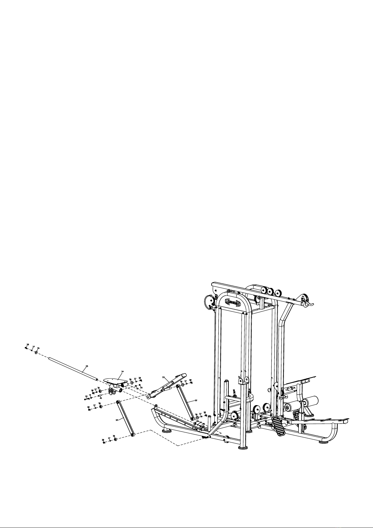
STEP 9:
Attaching Seat Back Support Tube, Seat Handles,
Cam, and Seat Back Adjustment Lever, Scissor
Flat Strap, & Gas Piston to Seat Frame
First attach the seat back support tube to the 4 flat strap metal pieces using 4
short axles. The axles go through the holes at back support tube at the top
holes of the flat straps as well as through the bottom holes on the flat strap
metal pieces secured by bolts, washers, and nuts. Note that one of the 4 flat
straps has a pie shaped metal wedge with Holes and this must go in the forward
most position. Attach the gas piston to the flat strap and to the upright tube
under the seat.