MVE Fusion Series User manual

MVE Fusion Series
Quick Reference Guide

MVE FUSION Quick Reference Guide
2 –21205647 B
Table of Contents
NOTE: MVE Fusion cryogen freezer should be installed by Chart Personal or an
authorized MVE Distributor per the MVE Fusion Technical Manual, PN 20994124.
Product Identification
Display / Control Panel……………………………………………………………………………………………………………….3
Bottom Panel / Electrical / Physical Connections ……………………………………………………………………….4
Dewar Plumbing Connections…………………………………………………………………………………………………….5
Setup/Filling Procedure ……………..………………………………………………………………………………………………6
Calibration of Temperature Probe.…………………………………………………………………………………………….10
Alarms and Definitions………………………………………………………………………………………………………………11
Contact Information………………………………………………………………………………………………………………….11

MVE FUSION Quick Reference Guide
3 –21205647 B
Display / Control Panel
Table 1: Front Panel Identification
Front Panel
MVE FUSION Graphical User Interface (GUI)
Temp A and Liquid Nitrogen (LN2) % with Timeline Graph.
Display
A Liquid Crystal Display (LCD) shows the value of all the current
conditions including Temperature and LN2 level. The display also shows
any current alarm conditions that may exist.
Temperature Probe
Used to monitor internal Fusion freezer temperature.
Setup
Used to adjust the value of all the user adjustable functions including
Temperature, Alarms, Passwords, Etc.
Alarm Mute
Used to silence the audible alarm. Also used to reset the latching alarm
after the alarm condition is corrected.

MVE FUSION Quick Reference Guide
4 –21205647 B
Bottom Panel / Electrical / Physical Connections
1
Temp Probe
2
Global Alarm Contacts (These connections monitor All Alarms)
3
Service Port
4
Service Port
5
Input Power
6
Main Power Switch
7
Battery Backup Switch
4
3
2
1
6
5
7

MVE FUSION Quick Reference Guide
5 –21205647 B
Dewar Plumbing Connections
1. Connect the transfer line to the LN2 supply tank. Optimum supply tank pressure is 22 to 35 PSIG
(1.5 to 2.4 bar).
2. Although the plumbing assembly has a 50 PSIG (3.45 bar) pressure relief device, it is
recommended the supply tank be pressurized below 35 PSIG (2.4 bar) to reduce the cryogen
“flash-off” rate during filling and to maximize the cryogenic valve life.
3. The transfer hose can be insulated to minimized liquid transfer losses.
4. Connect the other end of the transfer line to the MVE Fusion freezer fill valve.
5. After the transfer line has been securely coupled to the supply tank and freezer, the freezer is
ready to be filled with LN2
Vent Valve
PRV
Fill Valve

MVE FUSION Quick Reference Guide
6 –21205647 B
Set up / Filling Procedure
1. Load racks and empty boxes into the MVE Fusion. NOTE: VERY IMPORTANT TO ADD RACKS
AND BOXES BEFORE FILLING.

MVE FUSION Quick Reference Guide
7 –21205647 B
2. Connect the temperature probe to backside of the liquefier.
3. Shut off isolation valves. They are located underneath the shroud on both sides of the liquefier
4. Connect A/C electrical power to MVE Fusion power receptacle at the rear.

MVE FUSION Quick Reference Guide
8 –21205647 B
5. At startup, the MVE Fusion Controller Main Screen will automatically display by default. Below
shows the default LCD startup order. No programming required for the first fill. MVE Fusion
Password: Fusion01
6. The Lid is installed during the fill process.
7. For the first charge, or if the inner tank is warm, fill the storage area with 20-30 liters of LN2
through the neck of the tank with an LN2 supply tank. Then using a second LN2 supply tank, fill
the inner for the initial cool down. NOTE: This step may temporary cause a slight level
fluctuation displayed on the GUI.
8. Open the vent valve on the freezer to decrease freezer system pressure to a level well below the
supply tank pressure (This will create a pressure differential sufficient to push the LN2 from the
supply tank into the freezer). The vent valve will remain open until the freezer is filled with LN2.

MVE FUSION Quick Reference Guide
9 –21205647 B
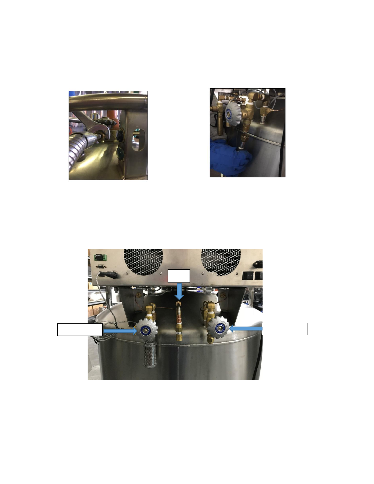
9. Open the fill valve on the freezer and then the liquid discharge valve on the supply tank.
Vent Valve on the left and Fill valve on the right View inside the storage area of the MVE Fusion
10. The LN2 will begin to flow from the supply tank into the freezer. As the cryogen vessel begins to
fill up, LN2 will periodically spray out of the freezer vent valve. When a steady stream of LN2
exits the vent valve, the cryogen vessel is full (the vent valve may spray and sputter for several
minutes prior to discharging a steady stream of liquid). The MVE Fusion first fill will take
approximately 35 to 45 minutes.
11. Once LN2 begins to flow steadily out of the vent, first shut off the vent valve, then second, shut
off the fill valve, then thirdly, shut off the fill valve on the supply tank.
12. Verify LCD displays % of Liquid (Turn on isolation valves on both sides). Wait until the transfer
hose thaws, loosen and remove the hose connection on the freezer inlet fitting.
13. The freezer’s pressure relief valve will begin releasing gaseous nitrogen as the liquid boils off
and build pressure (above 50 PSIG) inside of the storage tank. As the internal chamber and
storage racks come down to temperature the “relief” events will decrease.
14. Equilibration Period 1: Wait 12-18 hours and repeat steps 3, 8-11 to top off the cryogen vessel.
15. Equilibration Period 2: Wait an additional 24 hours and repeat the process (steps 1-6) again. At
this point all internal freezer surfaces should be at operating temperature and the cryogenic
vessel will be full and thermally stable.
Open fill valve

MVE FUSION Quick Reference Guide
10 –21205647 B
Calibration of Temperature Probe
Temperature sensor probe (A) used with the MVE Fusion has been calibrated at the factory
using the “Low Temperature Range” method. This calibration method provides a level of
accuracy of +/- 1.8◦F (+/- 1◦C) when operated in the altitude range of 1000ft to 1500ft (305m to
457m). Further calibration should not be required unless desired by the end user. Refer to the
MVE Fusion Technical Manual for information on calibration methods and procedures.

MVE FUSION Quick Reference Guide
11 –21205647 B
Alarms and Descriptions
Alarm Display
Description
TIP TEMP FAULT
CryoCooler Coldhead cold tip temperature (T1) fault
SYSTEM SHUTDOWN
System alarm shutdown
REJECT TEMP FAULT
Reject Temperature (T4) fault
MOTOR TEMP L FAULT
Motor Temperature L (T5) fault
MOTOR TEMP R FAULT
Motor Temperature R (T6) fault
TEMP A OPEN
Temp A (RTD1) open fault
MOTOR R OUT OF RANGE
Motor temperature R (T6) out of range
TIP TEMP OUT OF RANGE
Tip temperature (t1) out of range
REJECT T OUT OF RANGE
Reject Temperature (T4) out of range
MOTOR L OUT OF RANGE
Motor Temperature L (T5) out of range
TEMP A OUT OF RANGE
Temp A (RTD1) out of range
TEMP A SHORT
Temp A (RTD1) short
VIBRATION FAULT*
Vibration fault
LID OPEN
Lid open
BATTERY LOW
Battery low
LN2 OUT OF RANGE
LN2 out of range
GAS PRESS OUT OF RANGE
Gas Pressure (P2) out of range
VFD HARDWARE FAULT
VFD hardware fault
VFD OVER CURRENT
VFD over current
VFD OVER TEMPERATURE
VFD over temperature
If any alarms occur, contact your authorized MVE Distributor or Customer / Technical Service
Customer / Technical Service:
Phone: (800) 482-2473 Fax: (888) 932-2473

MVE FUSION Quick Reference Guide
12 –21205647 B
NOTES:

MVE FUSION Quick Reference Guide
13 –21205647 B
Chart Inc. reserves the right to discontinue its products, or change the prices, materials, equipment, quality, descriptions, specifications and/or
processes to its products at any time without prior notice and with no further obligation or consequence. All rights not expressly stated herein are
reserved by us, as applicable. Copyright © 2017 Chart Industries
21205647 Rev B
Other manuals for Fusion Series
2
Table of contents
Other MVE Freezer manuals