my!WIND 10 kW wind turbine User manual

my!WIND Ltd.
Soola 1a
51013 Tartu, Estonia
Email: info@mywind.ee
Website: www.mywind.ee
1 | P a g e 2 6 / 0 7 / 2 0 1 9
my!Wind Ltd
10 kW wind turbine
10m Tower Installation Manual

my!WIND Ltd.
Soola 1a
51013 Tartu, Estonia
Email: info@mywind.ee
Website: www.mywind.ee
2 | P a g e 2 6 / 0 7 / 2 0 1 9
Contents
Contents..................................................................................................................................................2
General remarks .....................................................................................................................................3
1. Introduction......................................................................................................................................4
2. Prior to installation...........................................................................................................................4
2.1 Important safety instructions...................................................................................................4
2.2 Building permits and zoning requirements..............................................................................5
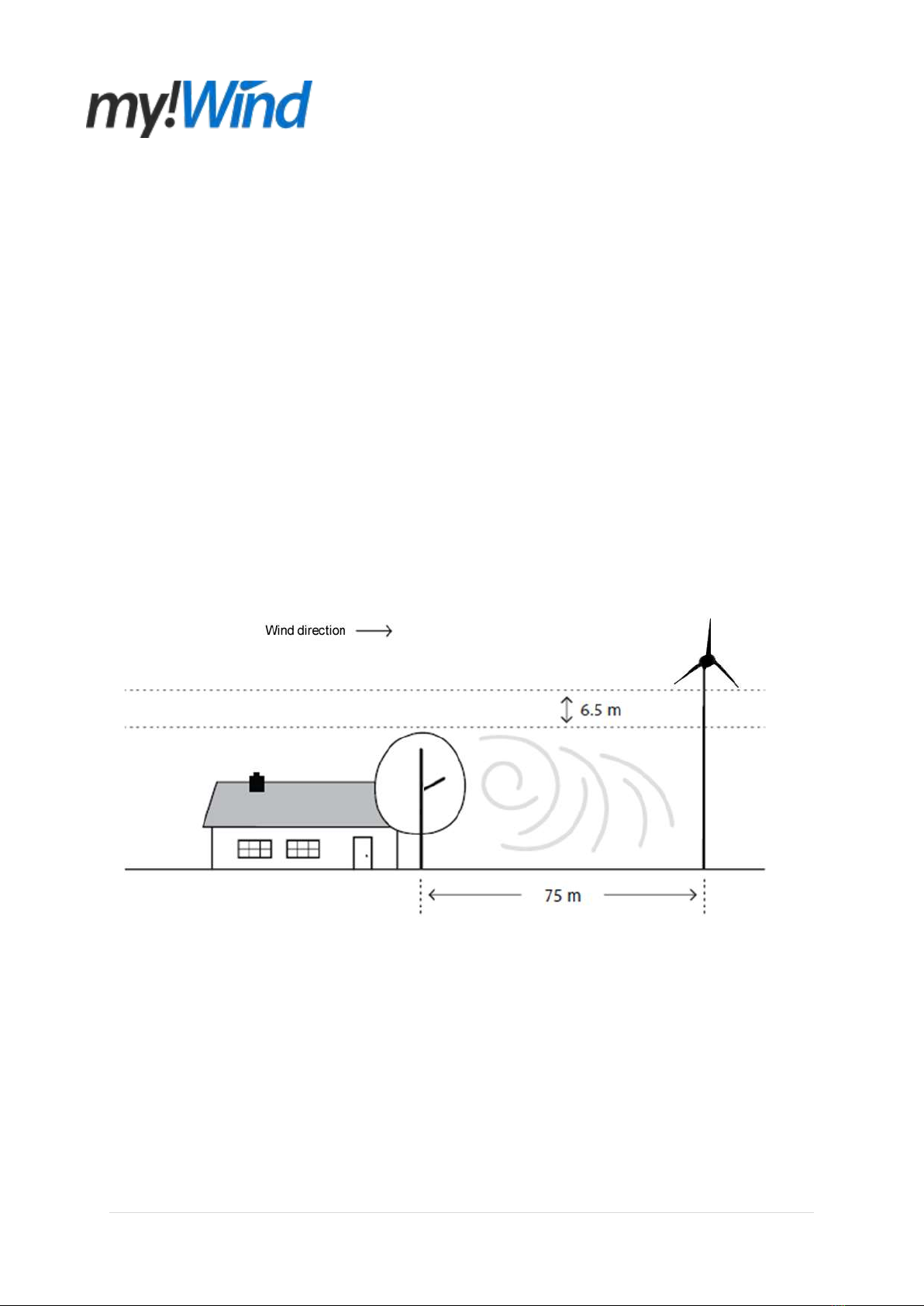
2.3 Siting .......................................................................................................................................5
3. Parts list...........................................................................................................................................7
4. Tools................................................................................................................................................8
5. Erection the of tower .......................................................................................................................9
Step 1: Placing the tower base plate...................................................................................................9
Step 2: Placing the tower 1st segment...............................................................................................10
Step 3: Placing the tower 2nd segment..............................................................................................11
Step 4: Placing the gin-pole...............................................................................................................12
Step 5: Placing the gin-pole cables...................................................................................................13
Step 6: Connecting the lifting equipment...........................................................................................14
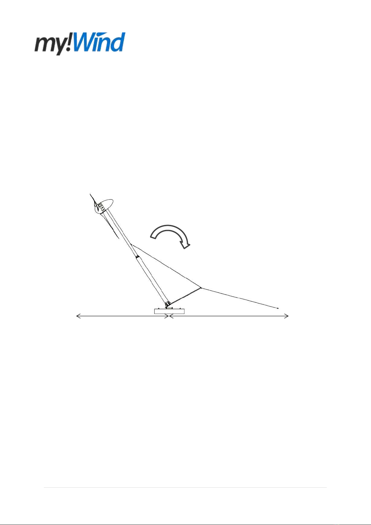
Step 7: Test lifting the tower..............................................................................................................14
Step 8: Levelling the tower................................................................................................................16
Step 9: Lowering the tower................................................................................................................16
6. Assembling the turbine..................................................................................................................17
Step 1: Placing the generator............................................................................................................17
Step 2: Repositioning the tower ........................................................................................................18
Step 3: Placing the cover holders......................................................................................................19
Step 4: Placing the blades.................................................................................................................20
Step 5: Placing the blade cover.........................................................................................................20
Step 6: Placing the nacelle cover......................................................................................................21

my!WIND Ltd.
Soola 1a
51013 Tartu, Estonia
Email: info@mywind.ee
Website: www.mywind.ee
3 | P a g e 2 6 / 0 7 / 2 0 1 9
7. Erection of the turbine...................................................................................................................22
Step 1: Lifting the tower.....................................................................................................................22
Step 2: Disconnecting the lifting equipment......................................................................................23
Step 3: Placing the tower junction box ..............................................................................................23
Annex 1 –Levelling the tower with ITS-2-45 dual axis inclinometer ....................................................25
Annex 2 –Tower verticality...................................................................................................................26
General remarks
Please read this manual thoroughly through before beginning the assembly. No guarantee is
assumed by my!WIND for the correct interpretation and application of the information by the
customer. In case any incomplete, incomprehensible or erroneous information is detected, the
circumstances must be clarified immediately my!WIND representative or local dealer.
This document supersedes any previously released version.

my!WIND Ltd.
Soola 1a
51013 Tartu, Estonia
Email: info@mywind.ee
Website: www.mywind.ee
4 | P a g e 2 6 / 0 7 / 2 0 1 9
1. Introduction
Overview of the my!Wind 10 kW turbine installation with a 10 m self-standing mast on a foundation
block is given in this document. The manual is solely intended to be used for a tower corresponding
with appendix 01 and for a foundation corresponding with appendix 02. Please DO NOT attempt to
use the manual for any other configuration of my!Wind products or for any products provided by other
suppliers. This can result in serious harm or loss of life.
Carefully read and understand the disclaimer at the beginning. While simple in concept, the
installation requires basic mechanical knowledge and attention to detail. Tools listed to erect the
turbine are readily available in most parts of the world or can be obtained from a distributor. When
even remotely possible use a my!Wind distributor who has received a corresponding training to carry
out the installation for you.
2. Prior to installation
2.1 Important safety instructions
1) Read, understand and follow all warnings.
2) Install foundation and tower in accordance with the electric code used in your country or region
and all local building and zoning codes and requirements.
3) Obtain building and construction permits prior to starting the installation.
4) Make sure that you have enough space for the erection before installing the foundation.
5) Foundation concrete must be completely cured prior to installing tower (Minimum 20 MPa, 28
day strength).
6) my!Wind uses high voltage and is potentially dangerous. Follow all safety precautions at all
times.
7) Remain at a safe distance when rising and lowering tower. NEVER stand or walk under tower
while it is being raised or lowered.
8) Be aware of overhead power lines.
9) Do not attempt to raise tower on a windy day (maximum wind speed 5 m/s).
10) Always wear personal protection equipment –closed toe shoes, work gloves, safety glasses and
hardhat.

my!WIND Ltd.
Soola 1a
51013 Tartu, Estonia
Email: info@mywind.ee
Website: www.mywind.ee
5 | P a g e 2 6 / 0 7 / 2 0 1 9
2.2 Building permits and zoning requirements
Building codes and installation requirements may vary greatly depending on state, city and local
townships. Be sure to obtain all required building permits BEFORE beginning the installation.
Be sure you understand all the installation and inspection requirements. Many localities require
inspections at key phases of the installation before next steps can be taken.
! IMPORTANT: Do not pour concrete before all required permits are obtained, inspections complete
and you are authorized to proceed.
2.3 Siting
The best location to install a wind turbine is often a compromise. Local building restrictions, the height
of surrounding structures, length of power cables and available open area may require the my!Wind to
be installed in a less then optimum location. In general my!Wind will produce more power if installed
on a taller tower. However, towers are expensive so it is important to balance performance to
installation costs, in order to achieve the lowest cost of energy and the quickest payback.
Figure 1 –Optimal location for the turbine
For optimal performance, install my!Wind in such a manner that blade tip at its lowest position is
6.5 m above any surrounding object within a 75 m radius (see Figure 1). For example in case a 10 m
tower is used, there should be no objects in a 75 m radius, as the tip of the 3 m blade is located at
7 m above the ground.
In addition keep in mind where you plan to install the inverter system and gain access to the grid if it
planned to have a grid connected turbine. Lengthy power cables can substantially contribute to the
installation costs and generate higher losses in the energy conversion process. If a long distance is

my!WIND Ltd.
Soola 1a
51013 Tartu, Estonia
Email: info@mywind.ee
Website: www.mywind.ee
6 | P a g e 2 6 / 0 7 / 2 0 1 9
required between your turbine and the connection point, it will be necessary to use heavy gage wire to
reduce the resistance of the wire.
When raising the 10 m tower using the gin-pole kit, a minimum open area with approximately 32 m
length is required (see Figure 2). Slightly less than 14 m are required on one side of the foundation
(measured from the centre of the foundation) for the tower and turbine. Depending on the length of
the vehicle and the method used to raise the tower, over 18 m might be required on the other side of
the foundation for the vehicle, lifting cable and gin-pole. For an easier and safer assembly, this area
should be 7 m wide over the entire length, having 3,5 m to either side in order to accommodate the
turbine blades. Narrower area on the gin-pole and the lifting cable side might be sufficient dependant
on the used vehicle width.
Figure 2 –Required area for erection
If the tower is being erected on the side of a hill it will be much easier to raise the tower if it is
assembled to the uphill side of the base.
14 m
18 m

my!WIND Ltd.
Soola 1a
51013 Tartu, Estonia
Email: info@mywind.ee
Website: www.mywind.ee
7 | P a g e 2 6 / 0 7 / 2 0 1 9
3. Parts list
After purchasing my!Wind 10 kW turbine the client shall receive following items for the installation:
QTY
Part number
Description
1
5KW-MD-01.01.00.00.00
Generator
3
5KW-MD-01.01.04.00.00
Blade
1
5KW-MD-01.01.00.00.01
Blade cover
3
5KW-MD-01.01.00.00.02
Blade cover holder
1
5KW-MD-01.01.00.00.03
Nacelle cover
1
08 VBS 30 B9/T
Junction box
1
5KW-MD-01.02.01.00.00
Tower 1st segment
1
5KW-MD-01.02.02.00.00
Tower 2nd segment
1
5KW-MD-01.02.03.00.00
Tower base
2
DIN 912 –M5 x 16 - Zn
Cylinder Head Cap Screw
20
ISO 7380 - M8 x 20 - A2
Hexagon Button Head Screw
24
DIN 912 - M10 x 35 - Zn
Cylinder Head Cap Screw
6
DIN 933 - M16 x 40 - Zn
Hex-Head Bolt
16
DIN 933 - M20 x 45 - Zn
Hex-Head Bolt
2
DIN 975 - M27 x 500 - Zn
Threaded Bar
6
DIN 127 - A 8 - Zn
Spring Washer
20
DIN 125 - A 8,4 - A2
Washer
48
DIN 125 - A 10,5 - Zn
Washer
6
DIN 127 - A 16 - Zn
Spring Washer
6
DIN 125 - A 17 - Zn
Washer
16
DIN 127 - A 20 - Zn
Spring Washer
16
DIN 125 - A 21 - Zn
Washer
12
DIN 125 - A 28 - Zn
Washer
24
DIN 985 –M10 –Zn
Nylock hex Nut
16
DIN 934 - M27 - Zn
Hex Nut
! IMPORTANT: Inspect and unpack all the parts included in your installation kit besides the generator
and make sure that nothing is missing or damaged. Leave the generator in its transportation box for
easier assembly. Use the Parts List and this manual for assistance in identifying parts as you unpack
the shipment. In case some parts turn out to be missing or damaged, do not continue the assembly
and contact your local distributor or my!Wind representative for assistance.

my!WIND Ltd.
Soola 1a
51013 Tartu, Estonia
Email: info@mywind.ee
Website: www.mywind.ee
8 | P a g e 2 6 / 0 7 / 2 0 1 9
4. Tools
Dependant on the installation method and desired installation speed a certain tool nomenclature is
necessary.
QTY
Description
Notes
1
Spirit level
At least 300 long
1
41 mm wrench
2
30 mm wrench
2
24 mm wrench
2
17 mm wrench
2
8 mm hex key
2
5 mm hex key
1
4 mm hex key
1
Socket wrench set
30, 24 and 17 mm sockets
1
Torque wrench
Up to 1080 Nm
1
Hammer
Big size
1
Crowbar
1
Pliers
Flat nose
1
WD 40 oil
200 ml
10
Cable ties
200 mm length
2
Lifting sling
Rated at least 400 kg
1
11 m rod or 12 m strong blank cable
For pushing the wires through the tower
1
Fork lifter, tractor, crane
At least 400 kg of lifting force, at least 3000 kg of
pulling force
1
Truck with a winch (optional)
At least 3000 kg of pulling force
10
Wooden pallets or mast tripods (2 pcs)
To support the tower segments
1
Gin-pole
3
Shackle Us. Std M16
Rated at least 2000 kg
1
Cable 6x19-FC 8 x 6655 mm
rated at least 3800 kg, 2 x thimble ends
1
Cable 6x19-FC 8 x 6655 mm
rated at least 3800 kg, 1 x thimble end, 1 x hook
end
1
6 m ladder (optional)
For removing the connection cable
1
ITS-2-45 Dual axis inclinometer (optional)
For levelling the tower according to Annex 1
2
M4x10 screws (optional)
For fixing the inclinometer
1
3 mm hex key (optional)
For fixing the inclinometer

my!WIND Ltd.
Soola 1a
51013 Tartu, Estonia
Email: info@mywind.ee
Website: www.mywind.ee
9 | P a g e 2 6 / 0 7 / 2 0 1 9
5. Erection the of tower
Before starting the tower erection, following steps must be completed:
1. The foundation has been manufactured according to appendix 02 and has had at least 28
days to cure.
2. All the parts have been inspected and unpacked and deemed to be of right quantity and
quality.
3. All the tools have been acquired and their presence has been verified.
Step 1: Placing the tower base plate
1. Place four pairs of M27 nuts onto the M27 threaded bars and place A 28 washer on top of
each pair (see Figure 3). Adjust the upper nut surface to roughly 95 mm from the foundation
surface. Use WD-40 oil to lubricate the nuts before placing them on the bars.
2. Place the tower base plate onto the washers and use a spirit level to level the base plate in
the horizontal plane. Do so by turning the upper M27 nuts up and down as far as needed.
! HINT: Do not push the bottom nuts against the upper nuts before levelling out the base
plate. This will make the adjustment process faster. Take not of the base plate placement in
terms of lifting equipment to have enough space available at the right sides.
3. Place A 28 washer onto each threaded bar and on top of the base plate.
4. Place M27 nuts onto each threaded bar and fix them cross wise with a torque of 1080 Nm,
going first 50% and then 100%.
5. Push the bottom counter nuts against the upper nuts and fix them with a torque of 540 Nm.
Figure 3 –Placing the base plate

my!WIND Ltd.
Soola 1a
51013 Tartu, Estonia
Email: info@mywind.ee
Website: www.mywind.ee
10 | P a g e 2 6 / 0 7 / 2 0 1 9
Step 2: Placing the tower 1st segment
1. Place the tower 1st segment hinge between base plate hinges (see Figure 4). The 1st segment
weighs about 285 kg, therefore a lifting aid in form of a tractor, fork lifter or a crane is
necessary to perform the operation. Use synthetic lifting slings to make contact with the tower
1st segment in order not to damage the zinc layer. ! IMPORTANT: Make sure you DO NOT
place any body part underneath the lifted object while it is being lifted.
2. Once the tower segment hinge and base plate hinges are coaxial, place the M27 x 500
threaded bar through the hinges.
3. Place A 28 washers onto both ends of the threaded bar.
4. Place M27 nuts onto both ends of the threaded bar and fix them by hand only.
Figure 4 –Placing the 1st segment
5. Place the mast tripod or wooden pallets with a height of 0,7 m underneath the 1st segment
approximately 2,6 m from the foundation edge (see Figure 5).
6. Lower the tower 1st segment onto the tripod or pallets and release the lifting equipment.
! IMPORTANT: Make sure that the segment is securely supported and shall not fall over.

my!WIND Ltd.
Soola 1a
51013 Tartu, Estonia
Email: info@mywind.ee
Website: www.mywind.ee
11 | P a g e 2 6 / 0 7 / 2 0 1 9
Figure 5 –Supporting the 1st segment
Step 3: Placing the tower 2nd segment
1. Place the tower 2nd segment bottom against the 1st segment top (see Figure 6). The 2nd
segment weighs about 145 kg, therefore a lifting aid in form of a tractor, fork lifter or a crane is
necessary to perform the operation. Use synthetic lifting slings to make contact with the tower
2st segment in order not to damage the zinc layer. ! IMPORTANT: Make sure you DO NOT
place any body part underneath the lifted object while it is being lifted. Make sure that the
segment lifting eye is facing upward direction.
2. Fit eight M20 x 45 bolts with a spring washer and then a regular washer and place the bolts to
join the two segments. Use WD-40 oil to lubricate the bolts before placing them into the
threaded holes. Fix the bolts cross wise with a torque of 434 Nm, going first 50% and then
100%. ! TIP: When having trouble getting bolts into threads, rock the segment slightly up and
down.
Figure 6 –Placing the 2nd segment

my!WIND Ltd.
Soola 1a
51013 Tartu, Estonia
Email: info@mywind.ee
Website: www.mywind.ee
12 | P a g e 2 6 / 0 7 / 2 0 1 9
3. Place the mast tripod or wooden pallets with a height of 0,75 m underneath the 2nd segment
approximately 4,5 m from the foundation edge (see Figure 7).
4. Lower the tower 2nd segment onto the tripod or pallets and release the lifting equipment.
! IMPORTANT: Make sure that the segment is securely supported and shall not fall over.
Figure 7 –Supporting the 2nd segment
Step 4: Placing the gin-pole
1. Place the gin-pole hinge pipes between tower 1st segment hinge (see Figure 8).
2. Once the gin-pole hinges and tower 1st segment hinge are coaxial, place the M27 x 500
threaded bar through the hinges.
3. Place A 28 washers onto both ends of the threaded bar.
4. Place M27 nuts onto both ends of the threaded bar and fix them by hand only.
5. Lay the gin-pole a rest on the tower 1st segment.
Figure 8 –Placing the gin-pole

my!WIND Ltd.
Soola 1a
51013 Tartu, Estonia
Email: info@mywind.ee
Website: www.mywind.ee
13 | P a g e 2 6 / 0 7 / 2 0 1 9
Step 5: Placing the gin-pole cables
1. Take the 6x19 8 mm cable (connection cable) with thimbles at each end and connect it with
M16 shackles to the 2nd segment lifting eye (pos 1) and the gin-pole lower lifting eye (pos 2)
(see Figure 9 and 10).
2. Take the 6x19 8 mm cable (lifting cable) with thimble at one end and a hook at the other end
and connect the thimble end with a M16 shackle to the gin-pole upper lifting eye (pos 3).
3. Make sure that all the shackles are securely fastened and that the cables do not have knots
or twists in them.
Connection cable
Lifting cable
Figure 9 –Cable ends
Figure 10 –Placing the gin-pole cables

my!WIND Ltd.
Soola 1a
51013 Tartu, Estonia
Email: info@mywind.ee
Website: www.mywind.ee
14 | P a g e 2 6 / 0 7 / 2 0 1 9
Step 6: Connecting the lifting equipment
1. Lift the gin-pole up into a vertical position as much as the connection cable allows it.
2. Take the cable end with the hook and connect it to a lifting equipment. A tractor or a car with
a winch can be used in order to achieve at least 3000 kg of pulling force (see Figure 11). If
you are using a car with a winch, make sure that the car has all the brakes applied at all times
and is anchored to a strong point. The winch on the car must have a functional brake.
! IMPORTANT: Keep the lifting cable under pressure all the time to prevent the gin-pole from
falling down.
In this manual two different tower levelling techniques are presented. In Step 8 of this chapter, a
technique with the simple sprit level is presented. In case you have acquired or your distributor
possesses ITS-2-45 dual axis inclinometer, please follow the guideline in Annex 1 before proceeding
to Step 7 and in that case skip Step 8.
Figure 11 –Connecting the lifting equipment
Step 7: Test lifting the tower
1. Check that all the tower segments are firmly connected together and to the base plate. Check
that the gin-pole is connected to the 1st segment. Check that all the shackles and cables are
firmly secured to the segments, gin-pole and lifting equipment. Clear all the uninvolved
persons from the area. ! IMPORTANT: DO NOT raise the tower with a turbine until you have
raised and lowered the tower without a turbine. Never stand near or under the tower or gin-
pole when raising or lowering the tower.
2. Raise the tower slowly –carefully observing the tension in the cables. If your lifting equipment
does not have enough power or begins to slip, stop the lifting process immediately and gently
lower the tower back to the ground. DO NOT perform any pumping movement to gain more
power.
3. Raise the tower until nearly vertical but with tension still on the lift cable (see Figure 12).
Second person can now catch the gin-pole and lower it gently to the ground by applying
downward pressure. DO NOT allow the gin-pole to crash to the ground, this will but serious
strain on the system. ! IMPORTANT: Continue applying pressure on the gin-pole, till at least
2 tower bolts are fixed.

my!WIND Ltd.
Soola 1a
51013 Tartu, Estonia
Email: info@mywind.ee
Website: www.mywind.ee
15 | P a g e 2 6 / 0 7 / 2 0 1 9
Figure 12 –Catching the gin-pole
4. Fit eight M20 x 45 bolts with a spring washer and then a regular washer and place the bolts to
join the 1st segment to the tower base plate (see Figure 13). Use WD-40 oil to lubricate the
bolts before placing them into the threaded holes. Fix the bolts cross wise with a torque of
434 Nm, going first 50% and then 100%. ! TIP: When having trouble getting bolts into
threads, move the mast via gin-pole left to right or front to back. If necessary loosen slightly
pressure on the lifting cable but DO NOT relieve the downward pressure on the gin-pole.
Figure 13 –Fixing tower bolts

my!WIND Ltd.
Soola 1a
51013 Tartu, Estonia
Email: info@mywind.ee
Website: www.mywind.ee
16 | P a g e 2 6 / 0 7 / 2 0 1 9
Step 8: Levelling the tower
1. Unhook the lifting cable from the gin-pole to avoid any influence of side pressure.
2. Take a spirit level and place it against tower 1st segment to observe the tower verticality. This
must be done at two sides of the tower, 90 degrees from each other. TIP: Using magnetic
pullet level will make the observation process easier.
3. Adjust the tower vertical by turning the M27 nuts supporting the base plate up and down as
necessary (see Figure 14). Lower the bottom nuts away from the upper nuts before levelling
out the tower. ! IMPORTANT: Do the adjustment incrementally, 1 nut turn at the time. Never
remove the upper M27 nuts from the threaded bars, this could result in the tower falling down.
4. Once the tower is vertically levelled fix the M27 nuts cross wise with a torque of 1080 Nm,
going first 50% and then 100%.
5. Push the bottom counter nuts against the upper nuts and fix them with a torque of 540 Nm.
Figure 14 –Levelling the tower
Step 9: Lowering the tower
1. Take the cable end with the hook and connect it to a lifting equipment. If you are using a car
with a winch, make sure that the car has all the brakes applied at all times and is anchored to
a strong point. The winch on the car must have a functional brake.
2. Use the lifting equipment to put slight pressure on the lifting cable and gin-pole.
3. Remove 6 of the M20 x 45 bolts connecting the tower base and 1st segment. Second person
can now catch the gin-pole and apply downward pressure. ! IMPORTANT: DO NOT allow the
tower to start lowering by itself. This will but serious strain on the system.

my!WIND Ltd.
Soola 1a
51013 Tartu, Estonia
Email: info@mywind.ee
Website: www.mywind.ee
17 | P a g e 2 6 / 0 7 / 2 0 1 9
4. Remove the last 2 of the M20 x 45 bolts connecting the tower base and 1st segment.
5. Place a crowbar between the tower base plate and tower 1st segment on the gin-pole side
and apply slight pressure to lift the tower out of the stable position. Second person must
stabilize the tower from the gin-pole until the lifting equipment is able to hold the tower on its
own. After this do not stand near or under the tower or gin-pole lowering the tower.
6. Lower the tower slowly on to the tripods or pallets.
7. Keep enough pressure on the lifting cable to prevent the gin-pole from falling down.
6. Assembling the turbine
Step 1: Placing the generator
1. Remove lid and yaw system flange side of the generator transportation box (see Figure 15).
2. Place the generator package near the tower 2nd top, leaving approximately 1 m distance. The
generator package weighs about 230 kg, therefore a lifting aid in form of a tractor, fork lifter or
a crane is necessary to perform the operation. Use the strong base of the box to do the lifting.
! IMPORTANT: Make sure you DO NOT place any body part underneath the lifted object
while it is being lifted.
Figure 15 –Placing the generator
3. Run the two wires coming out from the yaw system through the mast and out of the 1st
segment hole for wires (see Figure 4). ! TIP: Use a long rod or a strong blank cable to
perform the operation.

my!WIND Ltd.
Soola 1a
51013 Tartu, Estonia
Email: info@mywind.ee
Website: www.mywind.ee
18 | P a g e 2 6 / 0 7 / 2 0 1 9
4. Push the yaw system flange against the tower 2nd segment top by moving the transportation
box. Make sure that holes in the yaw system flange align with the holes in the tower 2nd
segment top and that the flanges are approximately parallel to each other. If necessary adjust
the height of the transportation box or the tower according to the tower erection sequence.
5. Fit six M16 x 40 bolts with a spring washer and then a regular washer and place the bolts to
join the yaw system flange to tower 2nd segment top (see Figure 16). Use WD-40 oil to
lubricate the bolts before placing them into the threaded holes. Fix the bolts cross wise with a
torque of 222 Nm, going first 50% and then 100%.
Figure 16 –Fixing the generator
Step 2: Repositioning the tower
1. Use the lifting equipment according to the tower erection chapter to lift the generator out of
the transportation box and remove the box.
2. Place the mast tripod or wooden pallets with a height of 1,3 m underneath the 2nd segment
approximately 4,5 m from the foundation edge (see Figure 17).
3. Lower the tower 2nd segment onto the tripod or pallets. ! IMPORTANT: Make sure that the
segment is securely supported and shall not fall over.
4. Keep enough pressure on the lifting cable to prevent the gin-pole from falling down.

my!WIND Ltd.
Soola 1a
51013 Tartu, Estonia
Email: info@mywind.ee
Website: www.mywind.ee
19 | P a g e 2 6 / 0 7 / 2 0 1 9
Figure 17 –Repositioning the tower
Step 3: Placing the cover holders
1. Fit six M8 x 20 bolts with a spring washer and then a regular A2 washer and place the bolts to
join the three blade cover holders to the blade holder back flange (see Figure 18). Use WD-40
oil to lubricate the bolts before placing them into the threaded holes. Fix the bolts with a
torque of 27 Nm. TIP! Use the holes in the blade holder front flange to do the initial fixing with
a hex key.
Figure 18 –Placing cover holders

my!WIND Ltd.
Soola 1a
51013 Tartu, Estonia
Email: info@mywind.ee
Website: www.mywind.ee
20 | P a g e 2 6 / 0 7 / 2 0 1 9
Step 4: Placing the blades
1. Take a my!Wind blade and place it against the root tube flange. Align the 8 mm fitting holes in
the blade flange and the root tube flange to achieve the right position for the blade (see
Figure 19). NO BOLTS shall go through these holes.
2. Take 24 M10 x 35 bolts and fit them with A 10,5 washers and place the bolts to join the blade
flange to the root tube flange. Place A 10,5 washers to the end of the bolts and fix the bolts
with M10 nylock nuts. Use WD-40 oil to lubricate the bolts before placing nuts onto them. Fix
the bolts cross wise with a torque of 53 Nm, going first 50% and then 100%. TIP: Fix at first
two bolts with a small torque and then place to others. This will make the bolt placement
easier.
3. Once the blade is fixed, place a support under the blade tip or have another person hold it to
prevent the generator turning on the yaw axis. DO NOT allow the blade tip to be turned
against the ground.
4. Repeat the process for the other two blades.
Figure 19- Placing the blades
Step 5: Placing the blade cover
1. Take the my!Wind blade cover and place it from underneath onto the cover holders in a way
that the blades pass through the hole for blade (see Figure 20). Align the six fixing holes in
the cover and in the blade holders. Use two person to perform this job.
2. Take six M8 x 20 bolts and fit them with A 8,4 A2 washers and place the bolts to join the
blade cover to the cover holder flanges. Use WD-40 oil to lubricate the bolts before placing
Table of contents