8 Sectional Monopole Tower Foundation & Installation Manual, Revision A
CONSTRUCTING THE FOUNDATION
Foundation Drawings
Detailed technical drawings for the Pier, Mat and SMarT foundations are
provided in Appendices A, B and C respectively. The drawings are also
available on Southwest Windpower’s website (www.skystreamenergy.com).
The drawings were prepared by Tower Engineering Professionals (TEP),
Raleigh, North Carolina and reviewed and certified by a State of Arizona
Registered Professional Engineer.
The drawings are provided as a reference to assist with obtaining building
permits and with the construction approval process.
Note the foundation dimensions for the Pier and Pad, and Pier founda-
tions will vary based on the Soil Class and Wind Zone. The dimensions
for the SMarT and Mat foundations do not vary based on soil conditions.
These foundations assume Soil Class 5 (worst case) conditions exist and
are sized accordingly.
Wind Zones
The foundation dimensions are in part dictated by the maximum anticipat-
ed wind speed the turbine will experience. A larger (or deeper) foundation
is required to withstand higher speed winds.
The dimensions and construction details for each of the foundations will
change based on the anticipated wind speed. Refer to the accompanying
tables to determine your Wind Speed Zone and the location of the foun-
dation dimensions for your tower height and foundation type.
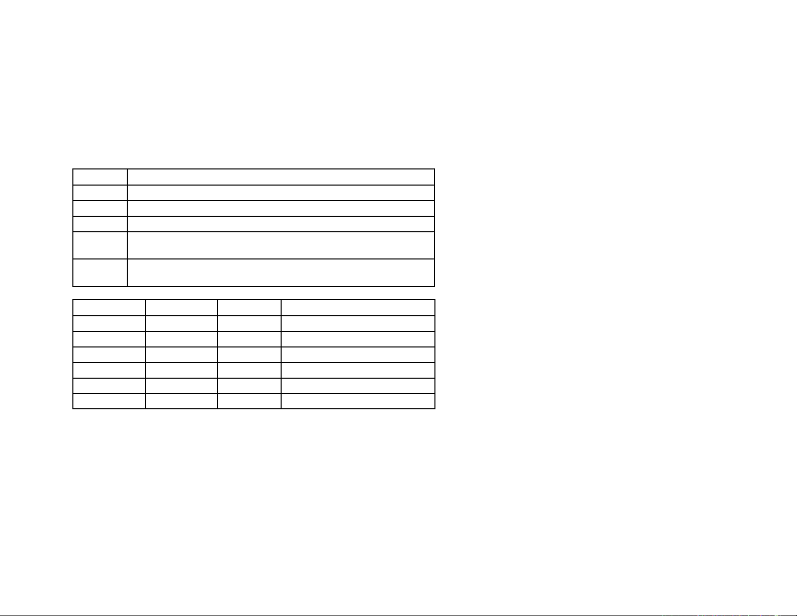
Wind Zones
Zone Wind Speed
1120 – 150 mph / 54 – 67 m / sec
290 – 120 mph / 40 – 54 m / sec
3< 90 mph / 40 m / sec
TIP: Excellent wind speed information is available on the internet at
http://www.awea.org/faq/usresource.html as well as other websites.
Tower Height Foundation Wind Zone For Dimensions See
33.5 ft (10.2 m) Mat 1Appendix A, Sheet S-4A
33.5 ft (10.2 m) Mat 2Appendix A, Sheet S-4B
33.5 ft (10.2 m) Mat 3Appendix A, Sheet S-4C
33.5 ft (10.2 m) Pier 1, 2 & 3 Appendix A, Sheets S-5 & S-6
33.5 ft (10.2 m) SMarT 1, 2 & 3 Appendix C, Sheet S-1
45 ft (13.7 m) Pier & Pad 1, 2 & 3 Appendix B, Sheet S-5 & S-7
45 ft (13.7 m) Pier 1, 2 & 3 Appendix B, Sheets S-8 & S-10
45 ft (13.7 m) SMarT 1, 2 & 3 Appendix C, Sheet S-1
Local building codes may specify the wind speed the foundation must with-
stand. If the building code does not specify a wind speed the local weather
service can provide maximum wind speed information.
TIP: If your installation requires “Wet Stamped” Foundation Drawings
for your state they may be purchased from Tower Engineering
Professionals, Raleigh , North Carolina. Phone: 919.661.6351.