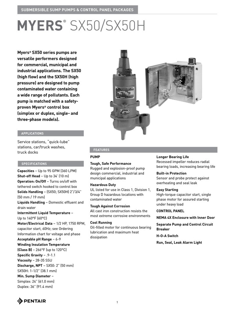
MYERS SX50 Manual

23833A465 03/10
SX50/SX50H
Sump Pumps
Used in Hazardous Locations Class 1, Division 1, Group D
Installation and Service Manual

GENERAL
1. Mostaccidentscanbeavoidedbyusing
COMMON SENSE.
2. Readtheoperationandmaintenance
instructionsmanualsuppliedwiththepump.
3. Donotwearlooseclothingthatcanbecome
entangledintheimpellerorothermoving
parts.
4. Thispumpisdesignedtohandlematerialsthat
couldcauseillnessordiseasethroughdirect
exposure.Wearadequateprotectiveclothing
whenworkingonthepumporpiping.
ELECTRICAL
5. Toreducetheriskofelectricalshock,pump
mustbeproperlygroundedinaccordancewith
theNationalElectricCodeandallapplicable
stateandlocalcodesandordinances.
6. Toreduceriskofelectricalshock,disconnect
thepumpfromthepowersourcebefore
handlingorservicing.
7. Anywiringtobedoneonpumpsshouldbe
donebyaqualiedelectrician.
8. Neveroperateapumpwithapowercordthat
hasfrayedorbrittleinsulation.
9. Neverletcordsorplugslieinwater.
10. Neverhandleconnectedpowercordswith
wethands.
PUMPS
11. Pumpbuildsupheatandpressureduring
operation;allowtimeforpumptocoolbefore
handlingorservicing.
12. Onlyqualiedpersonnelshouldinstall,
operateorrepairpump.
13. Keepclearofsuctionanddischargeopenings.
DONOTinsertngersinpumpwithpower
connected.
14. Donotpumphazardousmaterialnot
recommendedforpump(ammable,
caustic,etc.).
15. Makesureliftinghandlesaresecurely
fastenedeachtimebeforelifting.
16. Donotliftpumpbythepowercord.
17. Donotexceedmanufacturer's
recommendationformaximumperformance,
asthiscouldcausethemotortooverheat.
18. Securethepumpinitsoperatingpositionsoit
cannottipover,fallorslide.
19. Keephandsandfeetawayfromimpellerwhen
powerisconnected.
20. Submersiblesumppumpsarenotapproved
foruseinswimmingpools,recreationalwater
installations,decorativefountainsorany
installationwherehumancontactwiththe
pumpeduidiscommon.
21. Donotoperatepumpwithoutsafetydevices
inplace.
22. Forhazardouslocations,usepumpsthatare
listedandclassiedforsuchlocations.
IMPORTANT! Myersisnotresponsiblefor
losses,injuryordeathresultingfromafailure
toobservethesesafetyprecautions,misuseor
abuseofpumpsorequipment.
GENERALINFORMATION
PumpModels:Theseinstructionscoverthe
installationandserviceoftheMyersSX50and
SX50Hseriessubmersiblesumppumps.The
motorsareCSAlistedforhazardoussewage
locationsClass1,Div.1,GroupD.
MotorHP&Voltages:TheSX50/SX50Hsump
pumpsareofferedinsingleandthreephase.
Voltageswillvaryaccordingtotheapplicationand
canbeseeninthetablesinthismanual.
ElectricalControls:Allofthesepumpmodelsmust
beusedwithacontrolpanel.Myersbuiltcontrol
panelsaredesignedtosupplythecorrectelectrical
controls,motorstartingequipmentandinclude
thecircuitryformoistureandheatsensors.Itis
recommendedthataMyersbuiltcontrolpanelbe
usedsothatallwarrantiesapply.
GeneralConstruction:TheSX50/SX50Hmotor
constructionisdesignedtomeetCSArequirements
forClass1,GroupDsewageapplications.These
modelsareapprovedandnameplatedwithaCSA
lenumber.Acrosssectionalviewoftheinternal
workingsofthepumpscanbeseenonpages7and
8.Themotorchamberandsealchamberarelled
withahighdielectrictypeoilforimprovedlubrication
andheattransferofthebearingsandmotor.Since
thebearingshavebeendesignedfor50,000hours
oflife,theoilshouldneverrequirereplacement
23833A465 2
WARNING!IMPORTANTSAFETYINSTRUCTIONS!READCAREFULLYBEFORE
INSTALLATION.Thismanualcontainsimportantinformationforthesafeuseofthis
product.Readthismanualcompletelybeforeusingthisproductandrefertoitoften
forcontinuedsafeproductuse.DONOTTHROWAWAYORLOSETHISMANUAL.
Keepitinasafeplacesothatyoumayrefertoitoften.

undernormaloperatingconditions.Anairspace
abovetheoillevelinboththesealandmotor
chambersisprovidedtoallowfortheexpansionof
theoilwhenatoperatingtemperature.Thepower
andcontrollinesaresealedandstrainrelievedon
theoutsideentrancewithastandardcordgrip,and
internallythroughtheuseofadielectricpottingresin
surroundingtheelectricalwires.
Internalconnectionwiringdiagramsareshownin
Figure8.Allofthepumpfastenersandshaftsare
madefromcorrosionresistantstainlesssteel,while
thepumpcastingsaremadeofASTMA-48Class
30castiron,andthemultivanevorteximpellersare
madefromClass20castiron.
GeneralInstallation:Variouscongurationsand
methodsofplumbingthisseriesofsumppumpsmay
beused.
Note:IftheSX50/SX50Hhazardouslocation
pumpsareusedinconjunctionwitharaillift-out
system,itmustbeaULorCSAlistednonsparking
systemforhazardouslocations.
IMPORTANT:Ifthefollowingguidelinesare
notfollowed,theCSAhazardouslocationlisting
isvoid.
Thesepumpsaretobeusedforhandlingseptictank
efuent,sewage,andstormwateronly.Do notuse
inotherhazardouslocations.Thesemotorsmust
berepairedandservicedonlyataMyersauthorized
servicecenterorattheMyersfactory.Any
unauthorizedeldrepairvoidswarrantyandthe
hazardouslocationrating.
CAUTION:Afterthepumpisinstalledand
sewagehasenteredthebasinthereisDanger.
Sewagewatergivesoffmethaneandhydrogen
suldegases,whicharepoisonous.Never
enterawetwellunlessthecoverisopenfora
sufcientperiodoftimetoallowfreshairinto
thebasin.Itisrecommendedthatamanin
thebasinhaveaharnessonwitharopetothe
surface,sothathecanbepulledoutincaseof
asphyxiation.ItisforthisreasonthatMyers
recommendsusingtheraillift-outsystemsothat
noserviceisrequiredinsidethebasin.
Motor:Eachmotorisprovidedwithheatsensor
thermostatsattacheddirectlytothemotorwindings.
Thethermostatsopenifthemotorwindingssee
excessiveheatand,inturn,openthemotor
contactorinthecontrolpanel,breakingthepower
tothepump.Whenthemotorisstoppedduetoan
overheatcondition,itwillnotstartuntilthemotorhas
cooledandtheheatsensorresetbuttonismanually
pushedonthefrontoftheMyerscontrolpanel.
ThiscircuitryisprovidedintheMyerscontrolpanel
designs.
TheSX50/SX50Hpumpsareequippedwith
internalthermostats.TheSX50/SX50Hmodels
aredesignedtomeetClassBheatriseof266°F
(130°C).
Note:Failuretousepropercircuitryandtoconnect
themotoroverheatprotectioninthecontrolpanel
wouldnegateallwarrantiesandCSAListings.
MotorSealFailureWarning:Thesealchamberis
oillledandprovidedwithmoisturesensingprobes
todetectwaterleakagethroughthelowershaftseal.
Theprobescanalsodetectmoisturepresentinthe
uppermotorhousing.
Thepresenceofwaterenergizesaredsealleak
warninglightatthecontrolpanel.Thisisawarning
lightonly,anddoesnotstopthemotor.Itindicates
aleakhasoccurredandthepumpmustberepaired.
Normally,thisindicatestheoutboardsealhas
leaked.Allowingtheunittooperatetoolongafter
thewarningcouldcauseuppersealleakagealong
withmotorfailure.
Theresistanceacrossthemoisturesensing(seal
failure)probesshouldbecheckedafteraseal
leakwarninglighthaslit.Thiscanbedoneby
disconnectingtheredandorangecontrolwiresfrom
thecontrolpanel,andmeasuringtheresistancewith
anohmmeterbetweenthewires.TheSX50/SX50H
readingshouldbeabove30,000ohms.Ifthe
measuredvaluesarebelowthoseindicatedabove,
thepumpmayhavealowersealfailureand
requireservice.
OntheMyerscontrolpanelsthesealleaktestswitch
teststhesealleakcircuitcontinuity.Whenpushed
thesealleaktestbulbshouldlight.Ifthetestbulb
doesnotlightitmeanseitherthewiringcircuitryto
thesealleakprobeshavebeenbrokenorthebulb
hasburnedout.
Note:Myersbuiltcontrolpanelssupplythecorrect
circuitryformoistureandheatsensorconnections.
Failuretoinstallthecorrectcircuitrywithproper
connectionwouldnegatewarrantyandCSAListing.
SeeFigure7.
MotorPowerCord,ControlCordandCord
CapAssembly:Eachmotorpowercordhas4
conductors–white,black,redandgreen.Fora
singlephasemotortheblackisconnectedtothe
commonlead,thewhiteisconnectedtothemain
lead,whiletheredisconnectedtothestartcircuitry,
andthegreenisattachedtoagoodground.The
23833A4653

rotationofasinglephasepumpissetproperlyatthe
factory.
Forthreephasemotor,theblack,white,andred
conductorsarepowerleadsandthegreenisground.
Note:Rotationshouldbeclockwisewhenobserved
fromthetopofthepump.Thiscanbecheckedby
notingwhichdirectionthepumptorquesuponinitial
starting.Aproperlyrotatingpumpwilltorque
counterclockwiseuponstart.
ALWAYSCHECKTHREEPHASEPUMPS
FORPROPERROTATIONBEFORE
INSTALLINGPUMPS.
Thecontrolcablehas5conductors–black,white,
red,orangeandgreen.Whiteandblackconnect
totheheatsensorterminalsinthecontrolpanels;
redandorangeconnecttothesealfailureterminals
inthecontrolpanel;andthegreenconnectstothe
groundinthecontrolpanel.
Thecordcapisepoxypotted.Thisallowsthecord
cap,withcords,toberemovedfromthemotor.With
thisarrangement,thecordscanbepermanently
installedinasealedttinginthesump.This
shouldbeanapprovedjunctionboxforthespecic
hazardouslocations.The control and power
cables cannot be spliced!
Note:Eachcablehasagreengroundwireand
mustbeproperlygroundedpertheNationalElectric
Codeandlocalcodes.
ElectricalMotorControls:Allelectricalcontrols
andmotorstartingequipmentshouldbeasspecied
intheseinstructions.Consultfactoryforany
acceptablealternatives.Forhazardouslocationsthe
controlsandcontrolpanelmustbeinstalledoutside
thehazardousarea.Onlyapprovedcontrolsthatare
intrinsicallysafemaybeusedwiththesepumps.
JunctionBox:Ifajunctionboxisusedina
hazardouslocation,itmustbeanapprovedtype
withapprovedcordconnectors.Wiresfromthe
junctionboxmustpassthroughanapprovedseal
connectorforhazardouslocations.
LevelSensingControls:Intrinsicallysafe-type
oatcontrolsarerecommendedforallapplications
andrequiredforhazardouslocations.Anintrinsically
safecontrolpanelrelaywilllimitthecurrentand
voltagetothelevelcontrols.AMyerscontrolpanel
canbesuppliedwiththistypecircuitry.
Theoatlevelcontrolsmaintainthebasinsewage
waterlevelbycontrollingpumpturn-onand
turn-offlevels.
1. Thelowerturn-offcontrolshouldbesetsothat
thepumpstopswiththewatercoveringtheentire
motorhousing.Consultthefactoryforany
settingsbelowthispoint.
2. Theupperturn-oncontrolshouldbesetabove
thelowerturn-offcontrol.Theexactheight
betweenthetwocontrolsisdeterminedbythe
numberofpumpstartsdesiredandthedepth
ofthebasin.Amaximumof10startsperhour
shouldnotbeexceeded.
3. Theoverridecontrolissetataspeciedheight
abovetheupperturn-oncontrol.
4. Thealarmcontrolissetabout6"to12"abovethe
overridecontrol.
5. Nocontrolshouldbesetabovetheinletinvert.
ElectricalConnections:Allelectricalwiringmust
beinaccordancewithlocalcodeandonlyqualied
electriciansshouldmaketheinstallations.Complete
wiringdiagramsareincludedforuseinmakingthe
installation.Allwiresshouldbecheckedforshorts
togroundwithanohmmeterormeggerafterthe
connectionsaremade.Thisisimportant,asone
groundedwirecancausefailureofthepump,control
panelorpersonalinjury.
Pump:Theuidendofthepumpiseldserviceable
andcanbedisassembledincaseofwear,damage,
pluggingoroutboardsealfailure.Thefollowingwill
describethedisassemblyandreassemblyprocess.
WARNING!Disconnectpumpfrompowersource
beforeservicingorhandling.
Disassembly
1. Withthepumplocatedinasecureplace,remove
theboltsfasteningthesealhousingtothevolute.
Themotorandimpellercannowberemovedas
aunit.
2. Laytheunitdownonitsside.Ifthelowersealis
toberemoved,itisrecommendedthattheoilin
thesealchamberbedrained.Thiscanbedone
byremovingthelowersealchamberplugand
drainingtheoilintoaholdingcontainer.
23833A465 4

3. Usingaproperwrench,theimpellerretaining
nutmustberemoved.Thismayrequireapiece
ofwoodplacedbetweenthevanestokeepthe
impellerfromrotatingwhileremovingthenut.
Loctite®isusedonthisboltandheatingto
450–500°Fmayalsoberequiredtoloosen.The
impellerismountedonathreadedshaft.To
removeimpeller,rotateimpellerwithonehand,
whileholdingpumpshaftwithscrewdriver.
4. Ifthelowersealneedstoberemoved,rst
removethecompressionspringthatrides
betweentheimpellerandthesealassembly.
Nexttakeapairofscrewdriversandremove
thecompressionringthatsurroundstherubber
bellowsontherotatingportionoftheseal
assembly.Againusingthescrewdrivers,prythe
remainingportionoftherotatingsealassembly
offtheshaft.Theceramicstationarycanbe
removedbyplacingascrewdriverbetweenthe
rubberandtheceramicface,andthenprying,
workingaroundtheentirediameter.Note,
thesepartsshouldbediscardedandanewseal
assemblyinstalled.
5. Iftheoilinthesealchamberwasdrained,
examinethecontentstodetermineiftheupper
sealhasbeendamaged.Signsofgritorother
abrasivematerialmayindicatethattheupper
sealhasalsobeendamaged.Pressurizingthe
motorhousingassemblybetween7and10psi
andobservinganydropinpressurewillindicateif
theuppersealisfunctioningproperly.
Note:UppersealrepairsmustbedoneataMyers
authorizedservicecenterorattheMyersfactory.
Anyunauthorizedeldrepairvoidswarrantyandthe
CSAlisting.
Reassembly
1. Removetheceramicportionofthenewsealfrom
thepackage.Brushnewdielectricoilaroundthe
rubberportionofthestationaryassemblyandinto
thepocketinthesealhousing.Note,keepthe
oiloffthesealface.Withoutscratchingtheseal
face,presstheceramicstationaryportionintothe
sealhousing.ApieceofPVCpipethattsonto
thefaceofthesealworkswellforinstallation.
Withcleancloth,lightlywipethefaceoftheseal
surfacetomakesureitisdirtfree.Removethe
rotatingportionofthesealfromthepackageand
lubricatetheinsidediameteroftherubberbellows
andtheoutsidediameteroftheshaft.Placethe
sealovertheshaft.Evenlypressonthebody
oftherotationalassemblyandslideitdownthe
shaftuntilthesealfacesmeet.APVCpipewith
theinsidediameterslightlylargerthantheshaft
diametercanworkwelltopresstherotational
assemblyintoposition.Oncethesealassembly
isinposition,placethespringovertheregisteron
therotationalportionoftheseal.
2. Threadtheimpellerontotheshaft,makingsure
thatthesealspringisregisteredproperlyonto
thebacksideoftheimpeller.Placetheproper
Loctiteuidontheimpellerretainingnut.Tighten
nutonshaft.
3. Fillthesealchamberwithnewdielectricoil.An
airgapof10–15%volumemustbeleftforthe
expansionoftheoilwhenitisatoperating
temperature.
4. Themotorandimpellerassemblycanbeinstalled
intothevolute,makingsurethattheunitsare
alignedproperly.Installthevoluteretainingbolts
andtighten.
5. Airtendstotrapinthepumpcasewhenwater
risesinthesumporwhenthepumpislowered
intothewaterafterservice.Toventoffthisaira
smallholeisdrilledintothevolutecasting.Be
sure this vent hole is clean after any service
work on pump.Airventingisnotaproblemafter
initialstart.
23833A4655

SX50DIMENSIONS
[Dimensionsinmm]
SX50HDIMENSIONS
[Dimensionsinmm]
FIG.1
23833A465 6

SX50PUMPPARTS
FIG.2
23833A4657

SX50HPUMPPARTS
FIG.3
23833A465 8

SX50/SX50HPARTSLIST
23833A4659
Ref. Description Qty. SX50 SX50H
1 CAP, CORD 1 22407C602 22407C602
2 CONNECTOR 7 12762A001 12762A001
3 TUBE, PLASTIC x 1-1/4" LG. 2 10649A102 10649A102
4 SCREW, CAP 5/16 x 1-1/4" LG. 8 19100A012 19100A012
5 O-RING, 4-1/2" x 4-1/4" x 1/8" 1 05876A122 05876A122
6 CAP, UPPER BEARING 1 21570B100X 21570B100X
7 O-RING, 4-7/8" x 4-5/8" x 1/8" 1 05876A123 05876A123
8 PLUG, PIPE 1/4" NPT 2 05022A054 05022A054
9 SCREW, MACH. #10 x 1/2" LG. 1 05434A034 05434A034
10 WASHER, LOCK 1 06107A015 06107A015
11 SCREW, MACH. 5/16 x 1" LG. (SX50) 2 07597A017
11 SCREW, MACH. 5/15 x 1" LG. (SX50H) 6 07597A017
12 HOUSING W/STATOR (1Ø) 1 21571D150K 21571D150K
HOUSING W/STATOR (3Ø) 230/460V 1 21571D152K 21571D152K
HOUSING, MOTOR 21571D100X 21571D100X
STATOR ONLY (1Ø) 21656C103 21656C103
STATOR ONLY (3Ø) 230/460V 1 21656C106 21656C106
13 OIL, TRANSFORMER (1 GAL. CAN) 1.06 gal. 11009A008K 11009A008K
14 WASHER, SPRING 2 19331A005 19331A005
15 BEARING, BALL (UPPER) 1 08565A013 08565A013
16 RING, RETAINING 1 11816A006 11816A006
17 ROTOR W/SHAFT (1Ø) 1 26859C101X 26859C101X
ROTOR W/SHAFT (3Ø) 1 26859C104X 26859C104X
18 BEARING, BALL (LOWER) 1 08565A018 08565A018
19 HOUSING, UPPER SEAL 1 21574D100X 21574D100X
20 SEAL, SHAFT 2 21576A010 21576A010
21 RING, RETAINING 1 12558A006 12558A006
22 ELECTRODE W/RESISTOR 1 22578A003 22578A003
23 O-RING, 6-1/8" x 5-7/8" x 1/8" 2 05876A125 05876A125
24 FERRULE, RUBBER 1 22579A000 22579A000
25 PLUG, SPECIAL 1 21577A000 21577A000
26 HOUSING, LOWER SEAL 1 21578C110X 21578C115X
27 SCREW, CAP 5/16 x 1" LG. 4 06106A008 -----
28 CASE, VOLUTE 1 21612D000 26226D012
29 SCREW, CAP 1/4 x 1" LG. 3 19099A012 19099A012
30 IMPELLER, RECESSED 1 21663C020 21663C010
31 NUT, JAM 1 19109A070 19109A070
32 SCREW, SET 2 05013A027 05013A027
Available Models Motor Electrical Data
Standard HP Volts Phase Hertz Start Amps Run Amps
Service Factor
Amps NEC Code Letter Service Factor
SX50-21 ½ 230 1 60 12.5 4.9 5.9 H 1.2
SX50H-21 ½ 230 1 60 12.5 4.9 5.9 H 1.2
SX50-23 ½ 230 3 60 10.8 3.2 4.0 G 1.25
SX50H-23 ½ 230 3 60 10.8 3.2 4.0 G 1.25
SX50-43 ½ 460 3 60 5.4 1.6 2.0 G 1.25
SX50H-43 ½ 460 3 60 5.4 1.6 2.0 G 1.25
SX50/SX50H
MOTOR ELECTRICAL DATA

"
"
"
xx
23833A465 10
WIRINGDIAGRAMS
FIG.6
CORDCONNECTORS
NOTE:Allcomponentsshownmustbeapprovedforhazardouslocations.

23833A465 11
WIRINGSCHEMATICFOR230V,1ØSIMPLEXSYSTEM
FIG.7

23833A46512
WIRINGDIAGRAM230V,1Ø
FIG.8
WIRINGSCHEMATICFOR230V,3ØDUPLEXSYSTEM
XZ
NOTES:
1. Levelswitchesmustberatedaminimumof2amps@120V.
2. Torqueallwhiteeldwiringterminalsto8in.lbs.
3. Fieldwiringmustbe60°Ccopperwireminimum.
4. ----------=itemsnotsuppliedinpanel.

23833A465 13
WIRINGSCHEMATICFOR230V,3ØSIMPLEXSYSTEM
NOTES:
1. Levelswitchesmustberatedaminimumof2amps@120V.
2. Torqueallwhiteeldwiringterminalsto8in.lbs.
3. Fieldwiringmustbe60°Ccopperwireminimum.
4. ----------=itemsnotsuppliedinpanel.

23833A46514
WIRINGSCHEMATICFOR460V,3ØSIMPLEXSYSTEM
NOTES:
1. Levelswitchesmustberatedaminimumof2amps@120V.
2. Torqueallwhiteeldwiringterminalsto8in.lbs.
3. Fieldwiringmustbe60°Ccopperwireminimum.
4. ----------=itemsnotsuppliedinpanel.

23833A465 15
CheckingforMoistureinMotor:Usean
ohmmeterorameggerandsetonhighestscale.
Readingsonthelargepowercordbetweenany
oftheconductorsred,blackorwhitetothegreen
conductorortothemotorhousingshouldbe
greaterthan1,000,000ohms(megohm).Amotor
willprobablyrunwithalowerreading,butifthe
pumpisoutofserviceandthevalueofthereading
isbelow1,000,000ohms(1megohm),themotor
housingandstatorshouldberemovedandbaked
inadryingovenat220°F.Thisserviceworkshould
bedoneonlyatanauthorizedservicestation.
Note, readings should be taken with line leads
disconnected from the control panel.
ResistanceofWindings:Everymotorwindinghas
axedresistance.Thewindingsmustcheckclose
tothevaluesgiveninthetablestooperateproperly.
Seethemotorelectricaldatachart(Figure4).Use
anohmmeterandsettotheoneohmscale.Read
theresistancewiththemotorleadsdisconnected
fromthepumpcontrolpanel.
CHECKLISTIFPUMPDOESNOTOPERATEPROPERLY
WIRINGSCHEMATICFOR460V,3ØDUPLEXSYSTEM
XZ
NOTES:
1. Levelswitchesmustberatedaminimumof2amps@120V.
2. Torqueallwhiteeldwiringterminalsto8in.lbs.
3. Fieldwiringmustbe60°Ccopperwireminimum.
4. ----------=itemsnotsuppliedinpanel.

23833A46516
PROBABLECAUSE
Thisindicatessomewaterhasleakedpastthelowerseal
andhasenteredthesealchamberandmadecontact
withtheelectrodeprobe.Pumpmustberemovedfor
replacementoflowerseal.Thispreventiverepairwillsave
anexpensivemotor.
1. Pushinonredresetbuttontoresetoverload.If
overloadtripsagainaftershortrun,pumphassome
damageandmustberemovedfrombasinforchecking.
2. Troublemaybefromcloggedimpellercausingmotorto
overloadorcouldbefromfailedmotor.
3. Troublemaybefromfaultycomponentincontrolbox.
Alwayscheckcontrolboxbeforeremovingpump.
1. IndicatesH-O-AswitchmaybeintheHandposition.
2. Levelcontrolswitchmayhavefailedcausingpumpto
continuetooperatewhenwaterisbelowlowercontrol.
3. Impellermaybepartiallycloggedcausingpumpto
operateatveryreducedcapacity.
4. Gatevalveorcheckvalvemaybecloggedcausinglow
pumpow.
5. Pumpmaybeairlocked.
1. Resetbreakerbypushingcompletelydownonhandle
thenbacktoOnposition.Ifbreakertripsagaininfew
secondsitindicatesexcessiveloadprobablycaused
byashortinthemotororcontrolbox.Checkout
instructionsgivenwithcontrolboxbeforepullingpump.
2. Ifthisconditionhappensafteranelectricalstorm,
motororcontrolboxmaybedamagedbylightning.
3. Resistancereadingofthemotorwithleadwires
disconnectedfromthecontrolboxcandetermineif
troubleisinmotororcontrolbox.
1. Impellermaybepartiallycloggedwithsomeforeign
objectscausingnoiseandoverloadonthemotor.
1. Lowercontrolswitchmaybesettoohigh.
2. RunpumponHandoperationforseveralminuteswith
smallamountofwaterrunningintobasintocleanout
solidsandgrease.Thisallowspumptobreaksuction
andsurgewhichwillbreakupthesolids.Iflevelswitch
issetproperlythisconditiongenerallywillnotoccur.
3. Trashandgreasemayhaveaccumulatedaroundoats
causingpumptooperateerratically.
CONDITION
Redlightcomesonatcontrolbox.
Overloadtripsatcontrolboxandalarmbuzzerorashing
redlightcomesonduetohighwaterlevelinbasin.
Yellowrunlightstaysoncontinuously.
Circuitbreakertrips.
Pumpisnoisyandpumprateislow.
Greaseandsolidshaveaccumulatedaroundpumpand
willnotpumpoutofbasin.
IMPORTANT–Pumpshouldbethoroughlycleanedoftrashanddepositsbeforestartingdisassemblyoperations.
CAUTION–DISCONNECTALLPOWERANDCONTROLWIRESTOMOTORATCONTROLPANELBEFORE
STARTINGDISASSEMBLYOPERATIONS.NEVERRELYONOPENINGCIRCUITBREAKERONLY.

23833A465
NOTES

67$1'$5'/,0,7(':$55$17<
0\HUVZDUUDQWVLWVSURGXFWVDJDLQVWGHIHFWVLQPDWHULDODQGZRUNPDQVKLSIRUDSHULRGRIPRQWKVIURPWKHGDWH
RIVKLSPHQWIURP0\HUVRUPRQWKVIURP WKHPDQXIDFWXULQJGDWHZKLFKHYHURFFXUVILUVW SURYLGHG WKDWVXFK
SURGXFWV DUH XVHG LQ FRPSOLDQFH ZLWK WKH UHTXLUHPHQWV RI WKH 0\HUV FDWDORJ DQG WHFKQLFDO PDQXDOV IRU XVH LQ
SXPSLQJUDZVHZDJHPXQLFLSDOZDVWHZDWHURUVLPLODUDEUDVLYHIUHHQRQFRUURVLYHOLTXLGV
'XULQJWKHZDUUDQW\SHULRGDQGVXEMHFWWRWKHFRQGLWLRQVVHWIRUWK0\HUVDWLWVGLVFUHWLRQZLOOUHSDLURUUHSODFHWR
WKHRULJLQDOXVHUWKHSDUWVZKLFKSURYHGHIHFWLYHLQPDWHULDOVDQGZRUNPDQVKLS0\HUVUHVHUYHVWKHULJKWWRFKDQJH
RULPSURYHLWVSURGXFWVRUDQ\SRUWLRQVWKHUHRIZLWKRXWEHLQJREOLJDWHGWRSURYLGHVXFKDFKDQJHRULPSURYHPHQW
IRUSULRUVROGDQGRUVKLSSHGXQLWV
6WDUWXSUHSRUWVDQGHOHFWULFDOVFKHPDWLFVPD\EHUHTXLUHGWRVXSSRUWZDUUDQW\FODLPV:DUUDQW\LVHIIHFWLYHRQO\LI
0\HUVDXWKRUL]HGFRQWUROSDQHOVDUHXVHG$OOVHDOIDLODQGKHDWVHQVLQJGHYLFHVPXVWEHKRRNHGXSIXQFWLRQDODQG
PRQLWRUHGRUWKLVZDUUDQW\ZLOOEHYRLG0\HUVZLOORQO\FRYHUWKHORZHUVHDODQGODERUWKHUHRIIRUDOOGXDOVHDOSXPSV
8QGHUQRFLUFXPVWDQFHZLOO0\HUVEHUHVSRQVLEOHIRUWKHFRVWRIILHOGODERUWUDYHOH[SHQVHVUHQWHGHTXLSPHQW
UHPRYDOUHLQVWDOODWLRQFRVWVRUIUHLJKWH[SHQVHVWRDQGIURPWKHIDFWRU\RUDQDXWKRUL]HG0\HUVVHUYLFHIDFLOLW\
7KLVOLPLWHGZDUUDQW\ZLOOQRWDSSO\DWRGHIHFWVRUPDOIXQFWLRQVUHVXOWLQJIURPIDLOXUHWRSURSHUO\LQVWDOORSHUDWHRU
PDLQWDLQWKHXQLWLQDFFRUGDQFHZLWKWKHSULQWHGLQVWUXFWLRQVSURYLGHGEWRIDLOXUHVUHVXOWLQJIURPDEXVHDFFLGHQW
RUQHJOLJHQFHFWRQRUPDOPDLQWHQDQFHVHUYLFHVDQGSDUWVXVHGLQFRQQHFWLRQZLWKVXFKVHUYLFHGWRXQLWVZKLFK
DUHQRWLQVWDOOHGLQDFFRUGDQFHZLWKDSSOLFDEOHORFDOFRGHVRUGLQDQFHVDQGJRRGWUDGHSUDFWLFHVHLIWKHXQLWLV
PRYHGIURPLWVRULJLQDOLQVWDOODWLRQORFDWLRQILIXQLWLVXVHGIRUSXUSRVHVRWKHUWKDQIRUZKDWLWLVGHVLJQHGDQG
PDQXIDFWXUHGJWRDQ\XQLWZKLFK KDVEHHQUHSDLUHGRUDOWHUHG E\DQ\RQHRWKHUWKDQ0\HUVRU DQDXWKRUL]HG
0\HUVVHUYLFHSURYLGHUKWRDQ\XQLWZKLFKKDVEHHQUHSDLUHGXVLQJQRQIDFWRU\VSHFLILHG2(0SDUWV
:DUUDQW\([FOXVLRQV0<(560$.(612(;35(6625,03/,(':$55$17,(6:+,&+(;7(1'%(<21'
7+('(6&5,37,21217+()$&(+(5(2)0<(5663(&,),&$//<',6&/$,067+(,03/,(':$55$17,(6
2)0(5&+$17$%,/,7<$1'),71(66)25$1<3$57,&8/$5385326(
/LDELOLW\/LPLWDWLRQ,1 12 (9(17 6+$//0<(56%(/,$%/( 25 5(63216,%/( )25 &216(48(17,$/
,1&,'(17$/ 2563(&,$/'$0$*(65(68/7,1*)520 255(/$7(',1$1<0$11(572$1< 0<(56
352'8&7 25 3$576 7+(5(2) 3(5621$/ ,1-85< $1'25 3523(57< '$0$*( 0$< 5(68/7 )520
,03523(5 ,167$//$7,21 0<(56 ',6&/$,06 $// /,$%,/,7< ,1&/8',1* /,$%,/,7< 81'(5 7+,6
:$55$17<)25,03523(5,167$//$7,210<(565(&200(1'6,167$//$7,21%<352)(66,21$/6
6RPHVWDWHVGRQRWSHUPLWVRPHRUDOORIWKHDERYHZDUUDQW\OLPLWDWLRQVRUWKHH[FOXVLRQRUOLPLWDWLRQRILQFLGHQWDO
RUFRQVHTXHQWLDOGDPDJHVDQGWKHUHIRUHVXFKOLPLWDWLRQVPD\QRWDSSO\WR\RX1RZDUUDQWLHVRUUHSUHVHQWDWLRQVDW
DQ\WLPHPDGHE\DQ\UHSUHVHQWDWLYHVRI0\HUVVKDOOYDU\RUH[SDQGWKHSURYLVLRQKHUHRI
0\HUV3DUNZD\
$VKODQG2KLR
ZZZIHP\HUVFRP
23833A46503/10


START-UP REPORT
Distributor______________________________________________________Order #: _________________
Installing Contractor: _____________________________________ Phone: _________________________
Sales Contact: __________________________________________ Phone: _________________________
Customer & Location _____________________________________________________________________
1. SYSTEM INFORMATION
A. Size of wet well: __________________________________ Manufacturer:_____________________
B. Discharge from bottom of basin: ___________________ Location:__________________________
C. Inlet from bottom of basin:________________________ Location: __________________________
D. Type of check valves: ______________________________________________________________
E. Type of piping ____________________________________________________________________
F. Does system have suction and discharge gauges? _______________________________________
G. Pressure reading? Suction_____________________ Discharge _________________________
H. Liquid being pumped:____________________ Temperature: __________ % of solid: __________
I. Sketch or photograph of system attached? _____________________________________________
J. Any additional comments on system: __________________________________________________
__________________________________________________________________________________
2. ELECTRICAL INFORMATION
A. Control panel part #:__________________________ Panel rated amps: ___________________
Manufacturer ___________________________ Voltage: __________ Phase: _____________
B. Heater size: _____________________________________________________________________
C. Location of panel to wet well: ________________________________________________________
D. Incoming line voltage: _________________________ Actual? _____________________________
E. Voltage to pumps ____________________________ Actual? _____________________________
F. Type of junction box: _____________________________ Manufacturer:_______________________
G. Are floats installed in wet well? _______________________________________________________
H. Are floats set to engineer’s spec? ____________________________________________________
I. Are floats wired for proper sequencing? ________________________________________________
J. Any additional comments on electrical: ________________________________________________
__________________________________________________________________________________
3. PUMP INFORMATION
A. Type of pump:______________________________________ Serial # ______________________
B. Voltage:_____________ Phase:_____________ RPM:_____________ Amps: ___________
C. Impeller size: ______________ C.O.S. TDH:________________ GPM: ___________________
D. Voltage supplied from panel:___________________ Actual?: _____________________________
E. Actual amperage (all phases): _____________ amps _____________amps _____________amps
F. Have you checked pump rotation? ____________________________________________________
G. Any additional comments on pumps: __________________________________________________
__________________________________________________________________________________
Acknowledge that all information is accurate and proper procedures have been followed:
Customer Signature:__________________________________________________ Date ___________
Start-up Technician:__________________________________________________ Date __________
Send to: Warranty Department, 740 E. Ninth Street, Ashland, OH 44805, Fax: 419-207-3344,
or e-mail to: startupreport@myers.com
We will make this a permanent part of our file on this order.
cut along dotted line
Other manuals for SX50
1
This manual suits for next models
7
Table of contents
Other MYERS Power Pump manuals