MYUNGSAN MS850FHR Guide

manual-r-pul, 30p, 21 April, 2000
MYUNGSAN HYDRAULIC ROTATABLE PULVERIZER
OPERATION AND PARTS MANUAL
MYUNGSAN

1
Congratulations on your joining as a
MYUNG SAN customer
Myungsan pulverizer have been developed based on the long year’s accumulated
excellent design technologies. Several years field test ensures its durability and high
performance. However, the customer is kindly requested to read this manual and to
understand necessary instructions for the safe and long life usage. Any troubles caused
by improper maintenance, abnormal usage and repairs using non-genuine spare parts
can not be covered by warranty claims.
WARRANTY INFORMATION
WARRANTY is provided as part of the Myungsan support program for customers
who operate and maintain their equipment as described in this manual. Should the
equipment be abused or modified to alter its performance beyond original
specifications, the warranty will become void. Setting the carrier hydraulic
pressure above specification or changing the size of the attachment cylinder to
increase performance will also void warranty.
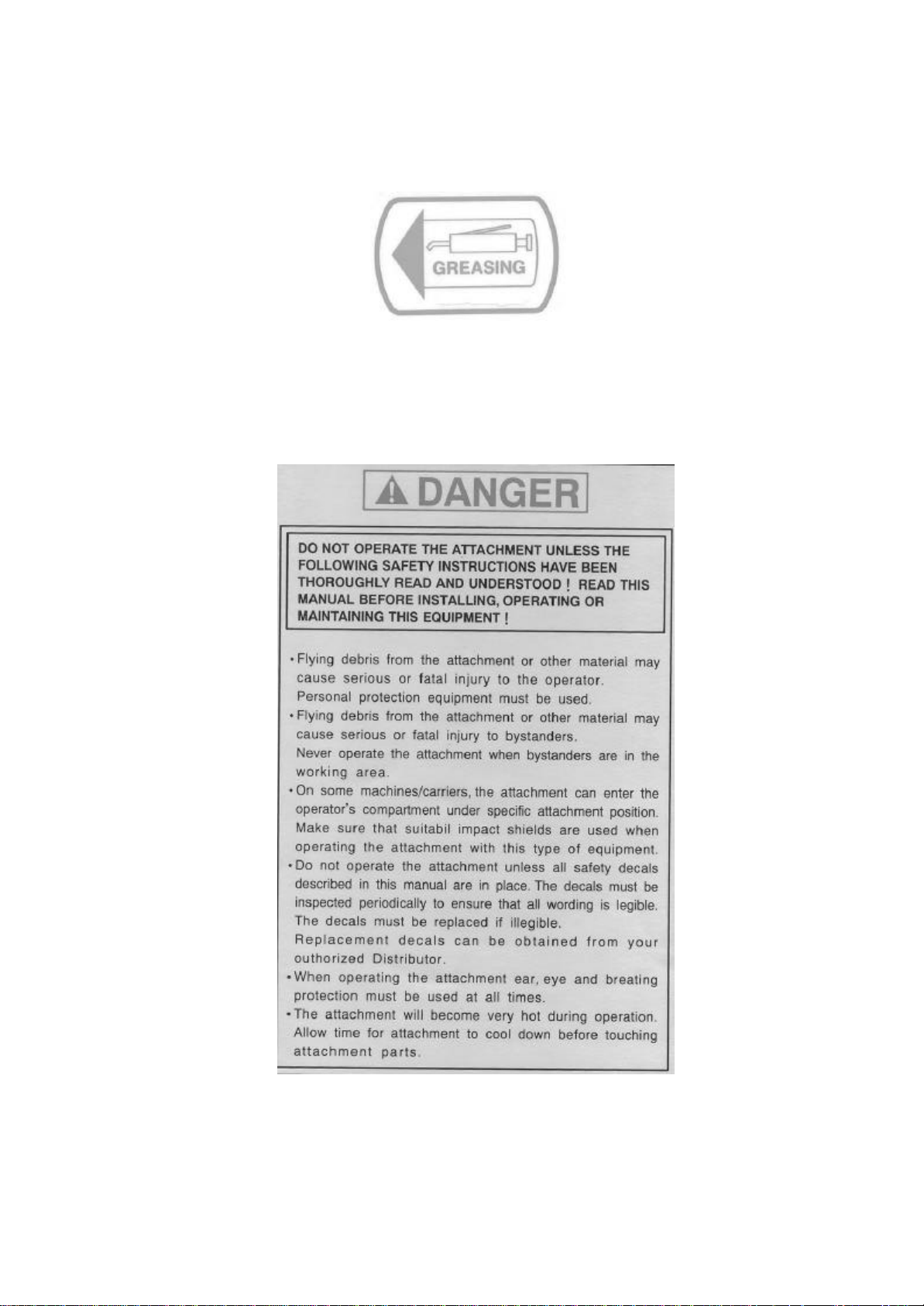
SAFETY FIRST
It is the responsibility of the operator
and service technician to read rules and
instructions for safe and proper
operation and maintenance.
A cautious worker using common sense
is the greatest safety device.

2
CONTENTS
CHAPTER 1. PRECAUTIONS AND SAFETY SYMBOLS … … … . … … … . … ...3
1.1 PRECAUTIONS
1.2 SAFETY SYMBOLS
1.3 LABEL LOCATIONS
CHAPTER 2. SPECIFICATIONS …………………………………………………..9
CHAPTER 3. EXTERNAL DIMENSIONS ……………………………………….10
3.1 MS850FHR
3.2 MS1000FHR
3.3 MS1300FHR
CHAPTER 4. INSTALLATION …………………... … … … … … … … … . … … . … ..11
4.1 GENERAL VIEW OF CRUSHER
4.2 HYDRAULIC CIRCUIT
4.3 PULVERIZER MOUNTING PROCEDURE
4.4 PULVERIZER REMOVAL PROCEDURE
CHAPTER 5. OPERATION AND MAINTENANCE … … … . … … … … … . … … .15
5.1 PRECAUTIONS FOR SAFE OPERATION
5.2 MAINTENANCE
CHAPTER 6. TROUBLE CAUSE AND REMEDY… … … . … … … … … … ... …..22
CHAPTER 7. EXPLODED VIEW AND PARTS LIST … … . … … … … … .. …. … 23
7.1 EXPLODED VIEW
7.2 PARTS LIST

3
CHAPTER 1. PRECAUTIONS AND SAFETY SYMBOLS
1.1 PRECAUTIONS
The Myungsan Hydraulic Rotatable Pulverizer can operate safely and normally if it is
operated in accordance with instruction given in this manual. Read this manual
thoroughly before operation. If operator do not understand necessary instructions
completely serious personal injury or equipment damage can occur.
(1) Observe all laws and regulations that affect you and your equipment when you
operate the pulverizer.
(2) Read the excavators operation manual and understand the safety and operation
instructions completely.
(3) Check all the necessary maintenance procedures are completed.
(4) The operator should quit the operation immediately if anyone moves in the working
area which is much larger than that of excavator due to the risk of flying debris.
(5) Before leaving the excavator, set the boom lower position and insure the excavator is
stable. Never leave the excavator while the engine is running. Fasten the parking
brake.
(6) Stop the engine when you want to repair or adjust the pulverizer.
(7) Keep temperature of the working fluid of excavator between 20 oC ~ 80oC for
proper performance.
(8) To avoid personal injury and pulverizer damage genuine parts of Myungsan should
be used. Also, only the authorized person or well trained person should repair the
pulverizer.
(9) Keep this manual near operator.

4
(10) Do not operate this pulverizer when you are under the influence of drug or alcohol.
(11) Detach pulverizer from excavator during transport.
(12) Observe the excavator manufacturer’s safety regulations.

5
1.2 SAFETY SYMBOLS
Your safety and the safety of others is a result of how you operate and maintain your
equipment. Read and understand this manual and other safety information provided
with the carrier machine. Carefully read all safety messages in this manual and on your
equipment safety signs. Keep safety signs in good condition, replace missing or
damaged safety signs.
Understand signal words
Indicates immediate hazards which will results in severe personal injury and death.
Indicates hazards or unsafe practices which could result in severe personal injury or
death.
Indicates hazards or unsafe practices which could result in damage to the machine or
personal injury.
GREASING
Indicates to fill cavity with recommended grease through the grease nipple before use.

6
1.3 LABEL LOCATIONS
ITEM DESCRIPTION
1GREASE DECAL- one at each grease fitting
2DANGER DECAL-1-one on front side of body
3DANGER DECAL-2-one on back side of body
4LOGO DECAL-one on front side of body
5MODEL DECAL-one on back side of body
6MODEL and SERIAL NUMBER plate-one on front side
of top bracket
7WARNING DECAL –one on back side of top bracket

7
ITEM 1 GREASE DECAL
ITEM 2 DANGER –1 DECAL

8
ITEM 3 DANGER-2 DECAL-2
ITEM 6 MODEL and SERIAL NUMBER PLATE
ITEM 7 WARNING DECAL

9
CHAPTER 2. SPECIFICATIONS
MODEL
ITEM MS850FHR MS1000FHR MS1300FHR
Cylinder Force
U.S (lb)
Metric (ton) 263,396
120 263,396
120 344,609
157
Attachment Weight-Approx
U.S (lb)
Metric (kg) 4,829
2,200 6,804
3,100 9,219
4,200
Carrier Weight-Approx
U.S (lb)
Metric (ton) 39,509-61,459
18-28 61,459-87,799
28-40 87,799-
153,648
40-60
90
2,296 100
2,543 126
3,200
Dimension
Length (in)
(mm)
Width (in)
(mm) 47
1,200 54
1,360 58
1,480
Jaw Opening
(in)
(mm) 33
835 36
926 43
1,100
4,651
320 4,651
320 4,651
320
Max. Working Pressure
Cylinder (psi)
(bar)
Motor (psi)
(bar) 3,052
210 3,052
210 3,052
210
100-200 100-250 150-300
Flow Range(Q)
Cylinder (lpm)
Motor (lpm) 10-20 10-30 10-40
1.31 1.30 1.52
Cycle Time(under Qmax
)
Open (sec)
Close (sec) 3.97 3.93 4.22

10
CHAPTER 3. EXTERNAL DIMENSIONS
Model Length(L) Width(W) Opening Width(O)
MS850FHR (in)
(mm) 90
2,296 47
1,200 33
835
MS1000FHR (in)
(mm) 100
2,543 54
1,360 36
926
MS1300FHR (in)
(mm) 126
3,200 58
1,480 43
1,100

11
CHAPTER 4. INSTALLATION
4.1 GENERAL VIEW
No Name
1Hydraulic Pump
2Oil Tank
3Main Control Valve
4Directional Control Valve for Cylinder
5Directional Control Valve for Rotating Motor
6Pedal Switch
7Electric Fuse

12
4.2 HYDRAULIC CIRCUIT

13
4.3 PULVERIZER MOUNTING PROCEDURE
1. Place the pulverizer on the ground(or wood block) with blocking to keep the pulverizer
level for installation.
2. Remove the bucket or other attachment following the manufacturer’s recommended
procedure.
Be careful not to contaminate the hydraulic system by plugging the hydraulic hoses.
3. With the jaws of the pulverizer facing the excavator, operate the excavator into proper
position, lining the excavator’s arm(second boom) into the top bracket pivot of the
pulverizer.
4. Pin the excavator’s arm and pulverizer top bracket pivot together.
5. Pick the pulverizer up into a proper position where the second linkage pin can be
inserted. Insert pin.
5. Connect the hydraulic hoses to the manifolds(or fitting) located on each side of the
Top bracket. Tighten the bolts or cap to the proper torque.
When installation is complete, fully extend excavator bucket cylinder to curl pulverizer.
Check for interference. Contact factory or authorized dealer if any interference occurs.
7. Lift the boom and slowly try the pulverizer rotate function and pulverizer open and close
function. Watch for hydraulic oil leakage.
Observe flow rate and pressure range(both cylinder and motor) or the warranty will
become void.

14
4.4 PULVERIZER REMOVAL PROCEDURE
1. Position the pulverizer under the boom of the excavator.
Trapped hydraulic pressure may be present after base machine is turned off. Extreme
caution must be taken when removing pulverizer hydraulic hoses or possible injury or
death could result.
2. Disconnect the hydraulic hoses. Be careful not to contaminate the hydraulic system
by plugging the hydraulic hoses.
3. Remove the bucket cylinder pin from the pulverizer mounting bracket.
4. Remove the arm pin of the excavator from the pulverizer mounting bracket.

15
CHAPTER 5. OPERATION AND MAINTENANCE
5.1 PRECAUTIONS FOR SAFE OPERATION
(1) Check the excavator position is stable.
(2) Do not use pulverizer like a lever.

16
(3) Do not pull or push object with pulverizer when cylinder is acting.
(4) Do not hit the pulverizer against the object.

17
(5) Inadequate operation can cause damage to the cylinder rod.
(6) Operate carefully not to hit the excavator with the pulverizer

18
5.2 MAINTENANCE
Inspection Items Check Points and Remedy
1. Bolts, Nuts, Snap-Ring, etc -Looseness, damage, missing
àTighten, replace
2. Cylinder-Rod -Damage on the surface of cylinder rod.
àSurface finishing or replace
3. Center-Joint -Oil leakage, or bolt looseness
àReplace seals, tighten the bolts
4. Cutter -Damage, gap more than 1mm due to
wear, breakage, and or bolt looseness
àReplace or tighten the bolts
5. Pins, Bush -Gap more than 1mm due to heavy wear or
breakage
àReplace
6. Rotation motor-malfunction -Problem of motor, pinion or bearing,
àAdjust brake valve pressure, Replace
7. Grease -Grease every 4~8 working hours
(Slew-ring, Pins, Gear)
8. Damage on the structure -Check crack, breakage, damage
àRepair
9. Oil leakage -Check piping and seals
àTighten, Replace seals
10. Pressure setting
-Check main relief pressure
àAdjust relief valve(280~300 bar)
-Check setting pressure of motor brake
valve and flow rate
àAdjust pressure(140-~210 bar) and
flow rate(10~40 lpm)
11. Fluid contamination -Check fluid(oil) contamination regularly
àReplace oil and filter

19
ROTATOR MAINTENANCE
The rotator is capable of 360 degree continuous rotations for easy, accurate crushing at all
angles. The rotator is to be used only as a positioning features, not as a means of bending or
breaking material. Use of he rotation feature for any other purpose may damage the rotation
components and may compromise the attachment’s warranty.
The rotation mechanism consists of a hydraulic motor driving a turntable bearing. Periodic
maintenance requirements include maintaining proper bolt torque and lubrication, these items
are detailed below.
BOLT TORQUING
The bolts connecting the turntable bearing are important maintenance area. After the first
eight hours of use the bolt must be retorqued. Bolts be retorqued only once and then must be
replaced if they loosen due to fatigue caused by stretching the bolt during torquing. If the
bolts continue to loosen, contact the dealer or factory. These bolts should be inspected daily
and replaced after 1,500 hours or 12 months.
TURNTABLE BEARING LUBRICATION
Rotating attachments in storage should be lubricated at least every six months. Equipment
operating frequently in extreme environments should be lubricated at least every eight hours.
If old grease is noted to be in good condition and free of contamination, the interval may be
extended. Conversely, if the old grease is contaminated or deteriorated, the interval should be
shortened.
LUBRICATION PROCEDURES
Bearings Are equipped with 1 to 4 grease fittings, depending upon model used. The grease
fittings will be located either on the outside of the bearing or on the upper head side plate. It is
recommended to rotate bearing while greasing in order to uniformly distribute the grease and
to most effectively flush out the old grease and contaminants. The bearing should be turned
through two full revolutions while greasing through any one fitting. Continue greasing until
clean grease can be felt exiting at the seals.
TURNTABLE BEARING LUBRICANTS
For normal operating conditions, periodic lubrication with lithium Grade 2 extreme pressure
grease is recommended. For operation below 0o C (32oF), Grade 0 is recommended.
Comparable lubricants produced by other reputable manufacturers not referred below may
also be used.
This manual suits for next models
2
Table of contents