Page 2 N-Tech Jets F-9F Panther Assembly Guide
Recommended Equipment:
Using appropriate equipment is important to your suc-
cess with this model. The equipment we recommend
has been tested and flown in this product. You can use
different brands, but the specifications must be simi-
lar.
Radio:
*We recommend an 8-10 channel radio for conve-
nience although technically the Panther only has 6
functions: Ailerons, Rudder, Elevator, Flaps, Throttle,
and Retracts.
*Qty 7 Airtronics 94851 Digital Metal Gear Servos
*Qty 1 Airtronics 94722 Digital Standard Servo
*Qty 2 750mm Extensions (for tail servos)
*Qty 4 500mm Extensions (from wing joint to receiv-
er)
*Qty 2 300mm Extensions (from Ail servos to wing
joint)
*Qty 1 100mm Extension (from steering servo to re-
ceiver)
*If your radio is only 6-8 channel, you’ll need QTY
3 Y-harnesses for the Aileron and Flaps and Steering/
rudder servos.
*Servo Lead retainers (Heat shrink, molded clips,
whatever is your preference
*Receiver Battery: We recommend either a 5 cell Ni-
MH pack of 1600 or more mAh rating, or a Li-FE
6.6v receiver battery with 1600mAh or more rating.
*Check your radio manufacturer’s recommendations.
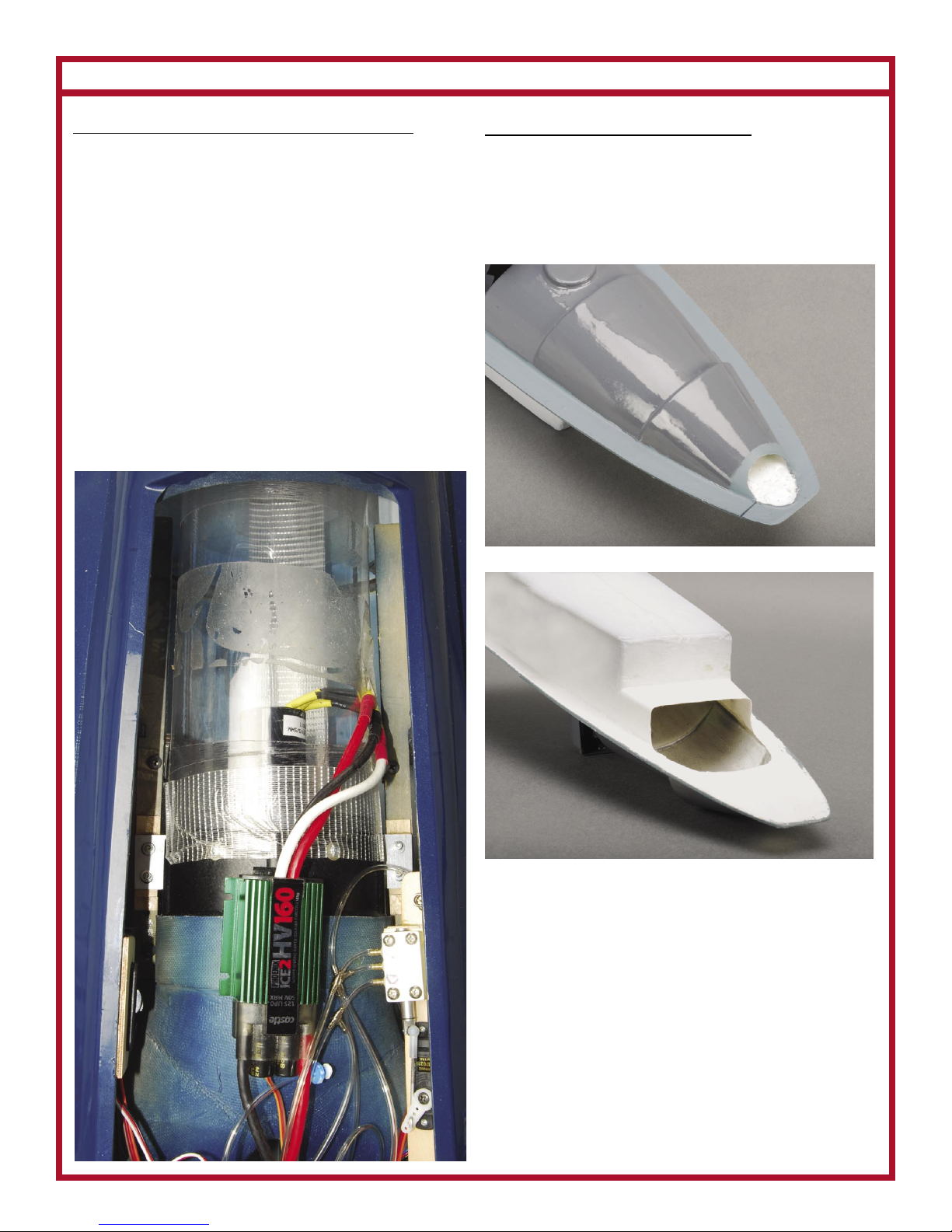
Power System:
*120mm Fan (Jet Hangar Hobbies E-Turbax fan with
13-15 pounds of thrust)
*12S Motor (Neu Motor for the E-Turbax fan)
*Castle 160HV (Some systems may be suitable with a
140HV esc, check your mfr’s specifications)
*12S 5000 to 6500mAh Li-PO packs, minimum 40C
rating (The airplane is setup for using two separate 6S
packs sometimes called Saddle Packs)
-6mm Gold Connectors (Castle 6.5mm connectors for
example)
-Mounting Screws for the Fan Unit (different fans may
have different requirements, we used #4 x 3/4 Dubro
Socket Head Wood Screws for mounting the E-Turbax
Fan)
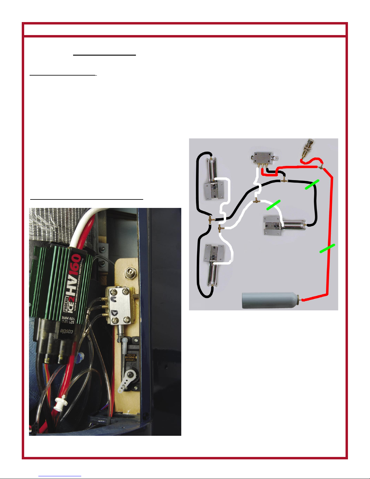
Other Items:
*The fuselage can be broken down into two parts, so
we installed air-line connectors at the fuselage break.
3 Air Line Disconnects will be required. Robart, Jet
Hangar Hobbies, or other similar air-line connectors
will work.
*Glues: We used Wood Glue, Epoxy, and C/A (in-
stant glue)
*Thread-lock, (blue or semi-permanent, do NOT use
“red” or permanent thread lock)
*Tape: Gaffer’s Tape or bi-directional Packing Tape
will work. This is to assemble the rear air-tube and
seal off the air between duct joints and around the
motor wires where they exit the exhaust air duct.
*Basic tools (file, wire cutter, pliers, hobby knife,
various metric hex-drivers, small drill bits, drill, etc)
*Paint to detail the cockpit (Optional)
*Small amount of fiberglass cloth (3/4 to 1 oz)
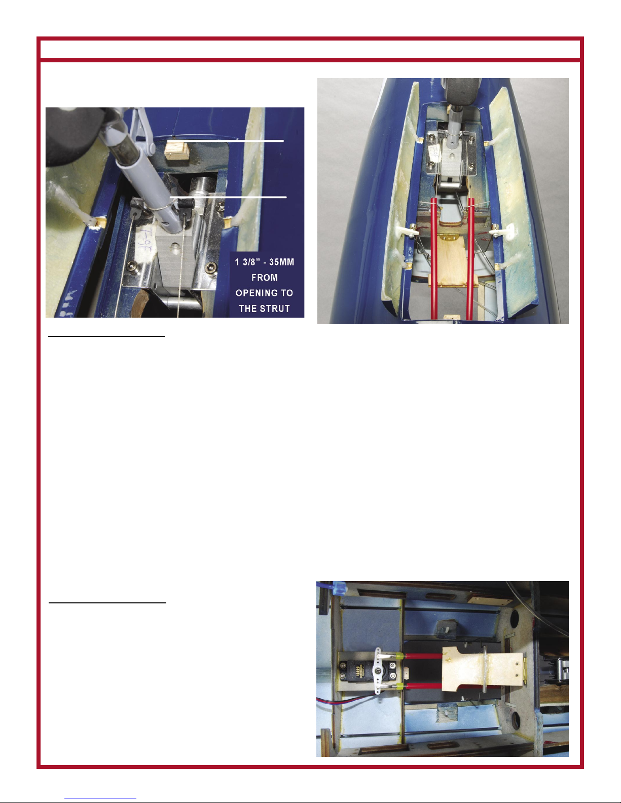
Wing Assembly
Aluminum Tube Wing Joiner
The wing is attached to the fuselage with an alumi-
num tube. One end of the tube must go into the fuse-
lage far enough to engage the clamp inside. The other
end is glued into the wing with epoxy. The clamp is
accessed through a small hole on the top of the fuse-
lage. Use a hex-tool to tighten the clamp. Loosen the
clamp to remove the wing half.
A Note About Assembly. Each N-Tech Jet is custom
made by hand. In that these are hand-made products,
there may be variations from what is shown in our
manual. Thus, it is important that you trial fit each
part before gluing, cutting, etc.
Let’s Get Started!