Wooden Model Boat Riviera Motor Boat User manual

Riviera Motor Boat
Part No. WBC1000
Specification Recommended Running Gear
Length 410mm Motor 280 brushed
Beam 120mm Speed controller 15A marine
Height 100mm Battery 7.4V 1100mAh LiPo
Finished weight 505g Prop shaft 150 x 2mm threaded
Propeller 30mm M2
Rudder 33 x 22mm brass
Coupling Neoprene tube
Radio 2.4GHz 2-ch proportional
Servo Mini or micro
WELCOME ABOARD!
Thank you for purchasing a Riviera Motor Boat kit. Based on a classic open cockpit 4-seater it’s a
design that epitomises a classic wooden runabout of the 1930s and ‘40s and, as such, we
sincerely hope you’ll enjoy many satisfying hours building, displaying and operating this model.
Here at the Wooden Model Boat Company we pride ourselves on producing traditional model
boat kits that build quickly and accurately into delightful semi-scale replicas, each as happy
cruising on the lake as it is adorning the mantelpiece at home. Using precise laser-cut balsa and
ply parts, coupled with a semi self-jigging / interlocking hull frame, success is practically
guaranteed, providing you closely follow these instructions. Whether you plan to build your
Riviera for two channel radio control or static display the build process is very similar, as are the
glues and materials you’ll need to finish and waterproof the boat (see Recommended Materials).
If you’re new to model boat building allow a quiet 30 minutes to read these instructions
carefully and to familiarise yourself with every part in the box, its function and when it’s required
in the assembly sequence.

LIST OF PARTS
You will find the following parts in the box. Please check the list carefully and contact your retailer
if anything is missing. Use this list in conjunction with the drawings of the laser-cut parts at the
end of this manual.
Part No. Description Quantity Material
1 Frame 1 3mm ply
2 Frame 1 3mm ply
3 Frame 1 3mm ply
4 Motor mount beam 1 3mm ply
4a Motor mount bracket 1 3mm ply
4b Motor mount nut (M3) 2 Mild steel
4c Motor mount bolt (M3) 2 Mild steel
4d Motor mount washer (M3) 2 Mild steel
5 Frame 1 3mm ply
6 Frame 1 3mm ply
7 Servo and battery tray 1 3mm ply
8 Transom 1 3mm ply
9 Keel 1 3mm ply
9a Keel doubler 4 1.5mm balsa
9b Keel trebler 2 1.5mm ply
10 Deck support 1 3mm ply
11 Chine stringer 2 3mm sq. ply
12 Gunwale 2 6 x 3mm ply
13 Stern skin 1 1.5mm ply
14 Rudder support 3 3mm ply
15 Bottom skin 2 1.5mm balsa
16 Side skin 2 1.5mm balsa
17 Bow profile blocks 28 3mm balsa
18 Bow deck coaming 1 3mm ply
19 Forward deck coaming 2 3mm ply
20 Aft deck coaming 2 3mm ply
21 Stern deck coaming 1 3mm ply
22 Spray rails 2 3mm sq. ply
23 Deck frame 1 3mm ply
24 Deck former 1 1.5mm ply
25 Deck former 1 1.5mm ply
26 Deck former 1 1.5mm ply
27 Deck former 1 1.5mm ply
28 Cockpit floor 1 Printed 1.5mm ply
29 Engine hatch 1 Printed 1.5mm ply
30 Deck 1 Printed 1.5mm ply
31 Windscreen 1 1mm Perspex
32 Steering wheel 1 1.5mm ply
33 Seat backs 2 Printed plastic
34 Deck magnets 2 (4 pcs) 6mm diameter
35 Riviera name plate 1 1.5mm ply
36 Flag pole 1 2mm dowel
37 Flag base large 1 1.5mm ply
38 Flag base small 1 4mm dowel
39 Stand end plates 2 3mm ply
40 Stand name plates 2 3mm ply
GENERAL INFO: STICK WITH US!
As one of the UK’s leading model and hobby distributors the team here at J Perkins are acutely aware that quality
tools and materials play a vital part in the successful completion of any model build. Fortunately our staff are active
modellers too, so we’re very fortunate in being able to both supply and thoroughly recommend the perfect glues,
paints and materials that are needed to complete your Riviera to a very high standard. We can do this because
we’ve built one too. Actually, more than one!
RECOMMENDED MATERIALS
The following is a list of the recommended materials you’ll need in order to complete the model as
depicted on the box and in the accompanying drawings and photographs (see jperkins.com).
Description J Perkins Part No.
MD Aliphatic White Glue: MDP5524821
ZAP Epoxy (15 min): 5525782-1
ZAP Canopy Glue (for the windscreen): 5525725-1
MD Super Filler: MDP5524830
500-Grit Sandpaper: –
800-Grit Sandpaper: –
1200-Grit Sandpaper –
Sanding block: –
Guild Lane Sanding Sealer 60ml jar): GLDCEX1100060
Guild Lane High Build Primer (400ml aerosol): GLDCEX0960400
Chroma Enamel Gloss White (400ml aerosol): GLDCHR6400
Chroma Enamel Gloss Dark Blue (400ml aerosol): GLDCHR6404
Oratrim Corsair Blue: ORA27-019-002
Guild Lane Gloss Fuel Proofer (400ml aerosol): GLDCEX1360400
Antique Pine Woodstain (for the deck): –
Low-tack double-sided tape: _
GENERAL INFO: IMAGES & VIDEO
For reference, a series of useful images detailing the finished model, along with a video of the Riviera on the water,
can be found on our website at jperkins.com. We hope you find this useful and encourage you to send images of
your own model when it’s finished; we’d love to see them.
STEP-BY-STEP
This assembly manual is divided into four sections: 1. Hull Frame Assembly; 2. Hull Skins &
Profiling; 3. Deck Substructure; 4. Deck Assembly; 5. Finishing; 6. Motor & Radio Installation. All
sections are supported by a build sequence whilst stages 1, 2, 3 & 4 are additionally supported by
an exploded illustration (with numbered parts) for easy identification. To avoid painting yourself
into a corner please follow these steps in precise order. Find yourself a clear, flat and solid surface
for assembly and make sure you have all the components, glues and materials necessary to
complete a stage before starting it.

Section 1: Hull Frame Assembly
Note that the hull frames are assembled upside-down on a solid, flat surface.
▢
1. Locate all the parts shown in the illustration above, along with the stand parts (39 & 40 –
see parts drawings at the end of the manual) and give all the brown, laser cut edges a light
sanding to aid glue adhesion. Glue the stand end plates (39) to the stand nameplates (40) and
leave to dry. Temporarily attach the deck support (10) to your flat building surface using six or
eight small pieces of paper-thin low-tack double-sided tape. This will ensure that no twisting
occurs during assembly of the frames and keel.
▢
2. Glue frames 1, 2, 3, 5 and 6 vertically into their respective locations and leave to cure.
▢
3. Take the four keel doubler pieces (9a), orientate them correctly, then glue two each side of
the keel (9) adjacent to the marked propeller shaft slot which is indicated by double dotted lines.
NOTE! Parts 9a must be located 1.5mm lower (in the direction of your building board) than the
keel line, this to allow the 1.5mm bottom skin (attached later) to sit flush with the keel. Now glue
one of the two keel treblers (9b) on one side only, directly over the top of parts 9a, lay the keel on
your building board and apply weights to 9b until cured.
▢
4. Lift the keel, flip it over and, using a razor saw, very carefully cut through part 9 (only) to
open out the propeller tube slot. Be very careful not to cut into part 9b. Keeping the keel
absolutely straight, glue the second keel trebler (9b) in position (to mirror the first) and clamp
until the glue has fully cured.
▢
5. Dry fit the keel, check it for accuracy, then remove, add glue and refit.
▢
6. Glue the angled transom (8) in position.
▢
7. Glue the chine stringers (11) in position from frame 1 to frame 8 and add the gunwales (12),
leave to properly cure, then carefully remove the completed frame assembly from your building
board.
▢
8. Using the supplied M3 nuts, bolts and washers (4b, 4c & 4d), bolt parts 4 and 4a together
then glue part 4 (only) between frame 3 and 5, as shown. Do not glue 4a to the keel as this will
need to be removed in order to fit the motor at a later stage.
▢
9. Glue the servo and battery tray (7) in position atop part 5 & 6.
Section 2: Hull Skins and Profiling
Fitting the hull skins is by far the most challenging part of any boat build, however with care and
attention it can also be one of the most rewarding. The old proverb ‘measure twice, cut once’ very
much applies here. In other words, plan thoroughly before you take action. In this instance that
means, carry out a dry run before fitting the parts, know in advance which glue you’re going to
use, work out how you plan to apply the skins and how you intend to hold the parts in place while
the glue is setting. Make sure you have all the required tools and materials to hand and then…
▢
10. Locate the three rudder support rings (14), glue them cleanly and accurately together, then
glue them to the inner surface of the stern skin (13), in perfect alignment with the hole for the
rudder tube. When set, glue part 13 in position with the forward edge located exactly half way over
frame 6.

▢
11. Check the bottom skins (15) for fit, mark the inner surface with the position of frames 1, 2, 3,
5 and 6, then apply contact adhesive to the marked lines. Apply contact adhesive to the mating
part of frames 1, 2, 3, 5 & 6 and leave for 10 minutes to dry. Dampen only the outer surface of the
bottom skins (15) with water (to assist in bending the wood), apply aliphatic white glue to the
mating edges of the skin and hull, then carefully position each skin and press into place. If the
forward edge of the skins prove difficult to attach to frame 2, use medium cyano and kicker to
finish the job.
▢
12. Check the outboard edge of the bottom skin and trim any overlap of the chine stringer.
Locate the side skins (16), check for fit and mark the inner surface with the position of frames 1, 2,
3, 5, 6 and 8, then apply contact adhesive to the marked lines. Apply contact adhesive to the
mating part of frames 1, 2, 3, 5, 6 and 8 and leave for 10 minutes to dry. Dampen only the outer
surface of the side skins, as before, apply aliphatic white glue to the mating edges of the skin and
hull, then carefully position each skin and press into place. If the forward edge of the skins prove
difficult to attach to frame 2, use medium cyano and kicker, as before.
▢
13. Trim the hull skins flush with frame 1, locate the bow profile blocks (17) and glue in position.
▢
14. Use sandpaper to shape and profile the bow blocks and sand the hull to a finish ready for
waterproofing. Pay particular attention to the chine lines, transom and bow, and use lightweight
filler as required.
▢
15. Locate the spray rails (22), cut a slope in the leading edge, and glue accurately to the lower
edge of the side skin, following the line of the chine (the junction of the bottom and side skins).
Section 3: Deck Substructure
▢
16. Locate the deck coaming parts (18, 19, 20, 21) and glue in position as shown.
TOP TIP: WETTING WOOD
Wetting balsa sheeting on one side softens the wood fibres and acts as a plasticiser which encourages increased
flexibility in the wood and allows the drier / stronger fibres (on the opposite side) to induce a bend in the direction of
the dry side. Gentle heat from, say, a household iron, has a similar effect.
▢
17. Locate the deck magnets (34) and separate into north and south poles. Glue two units with
identical poles into the deck support (10).
Section 4: Deck Assembly
▢
18. Locate the parts shown in the illustration above and give all the brown, laser cut edges a
light sanding to aid glue adhesion. Temporarily attach the deck frame (23) to your flat building
surface using six or eight small pieces of paper-thin low-tack double-sided tape. This will ensure
that no twisting occurs during assembly.

▢
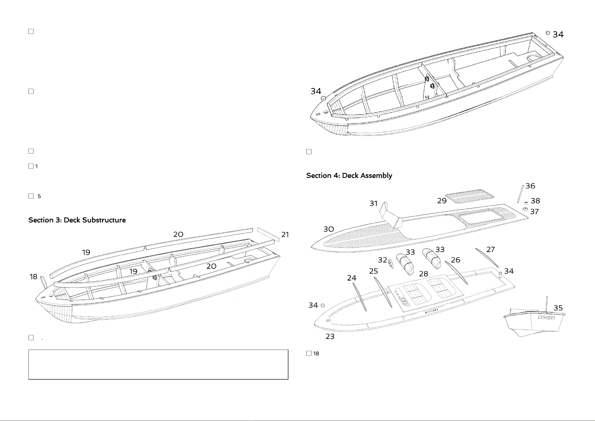
19. Glue the four deck formers (24, 25, 26, 27) and the cockpit floor (28) in position over the
deck frame. Ensure the deck formers remain vertical and are accurately ‘centered’.
▢
20. Locate the printed deck (30) and glue this accurately in position to the deck frame and
formers. If necessary wet the printed side of the wood to assist the bending process. In order for
the deck to clip snuggly onto the hull it’s essential that the deck frame (23) remains absolutely flat
during this process. If necessary use suitably heavy weights to hold the edges of the deck down
while the glue dries.
▢
21. Glue the engine hatch centrally over the hole in the rear deck.
▢
22. Assemble the flag pole and base from parts 36, 37 & 38 and glue to the stern as shown.
Section 5: Finishing
In this section we’ll make the boat waterproof and prepare for final installation of the radio
control and running gear.
▢
23. Unbolt the motor mount bracket (4a) and attach your chosen 280 brushed motor. Refit the
bracket / motor and slide your propeller tube into the hull. Accurately align the tube with the
motor shaft in both the vertical and horizontal planes, then permanently glue the shaft in place
using 15-minute epoxy. TIP! To guarantee alignment use a small piece of tight-fitting neoprene
tube to link the motor and shaft. When the epoxy has set, remove the motor.
▢
24. Trial fit the rudder tube, adjust as required (it should be absolutely vertical), then remove it
for refitting after the hull is painted.
▢
25. Apply two generous coats of Guild Lane sanding sealer to the hull and battery tray (7), leave
to dry between coats and sand after each coat with 800-grit (or similar) paper. If necessary,
repeat until you’re happy that the wood has been suitably sealed. Apply one generous coat of
Guild Lane High Build Primer to the hull, lightly sand with 1200-grit paper and check for
imperfections. Fill as necessary using lightweight filler, sand, re-prime then sand again until the
hull is deemed suitable for the gloss top coats.
▢
26. Add top coats to suit your chosen colour scheme. The prototype uses Guild Lane Gloss
White and Gloss Dark Blue enamel, plus Oratrim Corsair Blue for the trim line (see
Recommended Materials).
▢
27. Stain the deck and nameplate (35) as required (we used Antique Pine woodstain) and seal
with gloss varnish. Again, the prototype uses Guild Lane Gloss Fuel Proofer (see Recommended
Materials).
▢
28. Paint the cockpit floor as desired, along with the steering wheel (32) and seat backs (33),
then glue the steering wheel and seat backs in position.
▢
29. The Perspex windscreen (31) is supplied flat, pre-scored, with a protective film applied. Peel
away the protective film and gently bend the screen along the score lines to form the shape.
CAUTION! Bending the screen in two directions will snap it. The idea is to create a live hinge at
the score lines so that the screen can be formed and glued on in one piece. For this we suggest
Canopy Glue (see Recommended Materials).
▢
30. Locate the remaining deck magnets (34) and glue into the circular pockets in the deck
frame (23) making sure that the correct polarity orientation is observed. Glue the nameplate (35)
in position on the Transom.
Section 6: Motor & Radio Installation
We recommend the Planet TS2+2 two-channel radio system for the Riviera. Designed specifically
for boat and car modellers the stick-style system is supplied with a future-proof 6-channel
receiver and a competitive price tag. Visit jperkins.com for details and pricing and pick one up at
your local model shop.
▢
31. Refit the motor then join the motor shaft and prop shaft using tight-fitting neoprene tube.
NOTE! You may need to shorten the prop shaft by cutting a small length from the non-threaded
end.
▢
32. Fit the propeller and refit the rudder (making sure the O-ring seal is in place between the
rudder tube and hull), then tighten the rudder tube nut and washer against the top of the radio
tray.
▢
33. Attach your servo to the servo and battery tray (7) using double-sided servo tape and use a
piano wire pushrod to link it to the tiller arm.
▢
34. Use padded double-sided tape to attach your receiver (forward of the rudder servo), then
test the model for balance, in water. Establish the ideal location for your chosen 2S LiPo battery
then attach it using hook and loop tape. Check for leaks and rectify.
HAPPY CRUISING
The Riviera drives well in most conditions but, like all small model boats, excels in calmer water
and looks very much the part, displacing a satisfying bow wave and leaving a tidy wake. Steering
is positive and with the 280 motor / 2S LiPo combination the speed is beautifully matched to the
type. Don’t be tempted to over-power it. The Riviera has a semi-displacement (rather than a
planing) hull and is not designed for out-and-out speed. Like the full-size motor boat it
resembles, this is a gentleman’s Sunday cruiser and is best driven accordingly.
We hope you’ve enjoyed building this model and are suitably enthused to try other boats in
the Wooden Model Boat Company range.

LASER-CUT PARTS
Use these drawings to help identify the various laser-cut and printed parts that are included in
your kit.
This manual suits for next models
1
Table of contents
Other Wooden Model Boat Toy manuals