Nacecare TGB 2120 User manual

CAUTION, Read instructions before using the machine
Owner Instructions
RIDE-ON SCRUBBER DRYER
TGB 2120
TGB 2120
TGB2128
TGB2128

Machine Overview .................................Pages 2-3
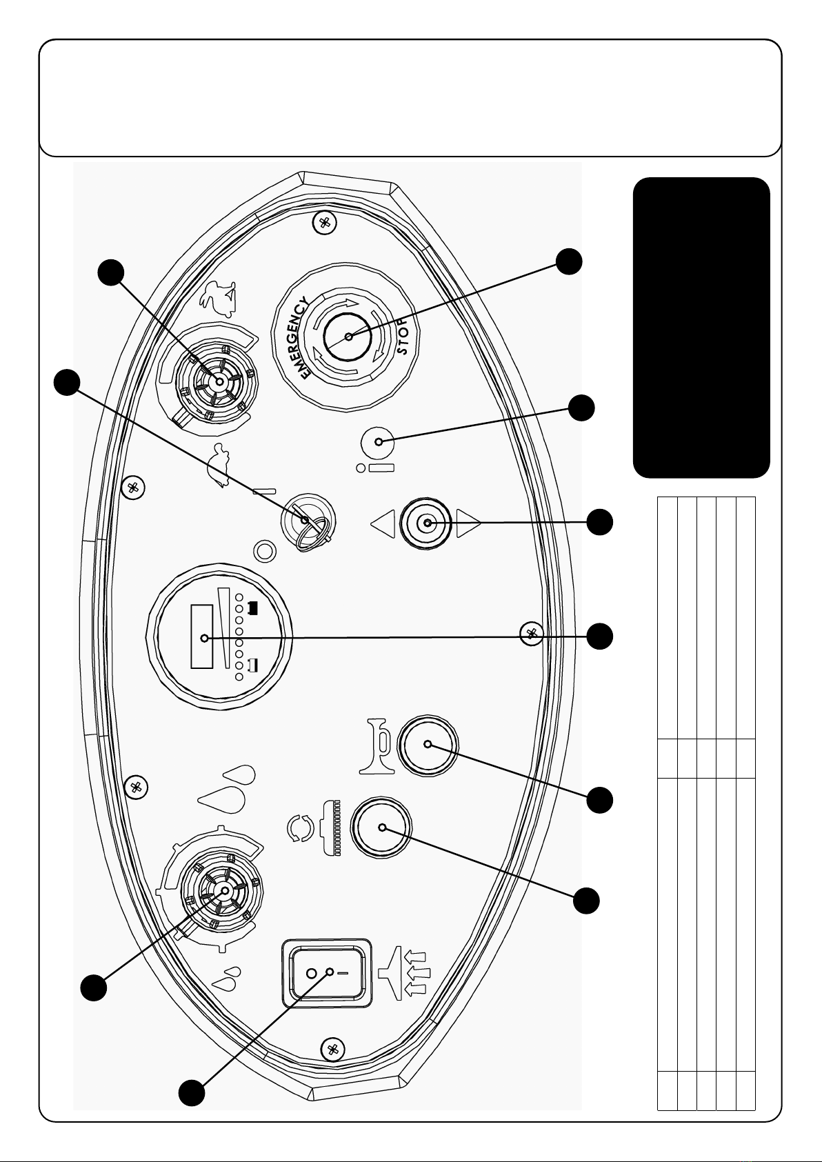
Control Panel Overview .................................Page 4
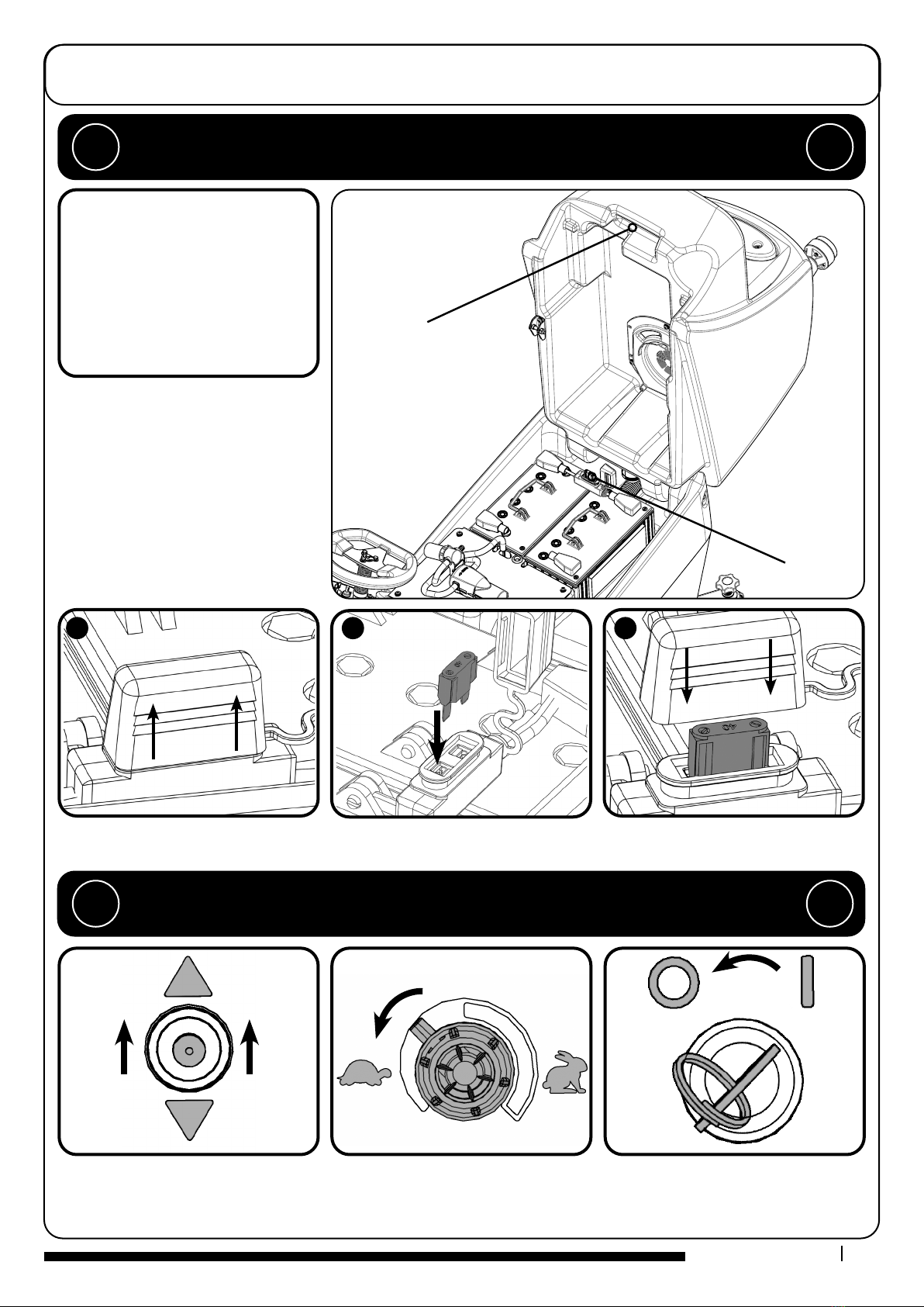
Machine Set up Guide .................................Page 5
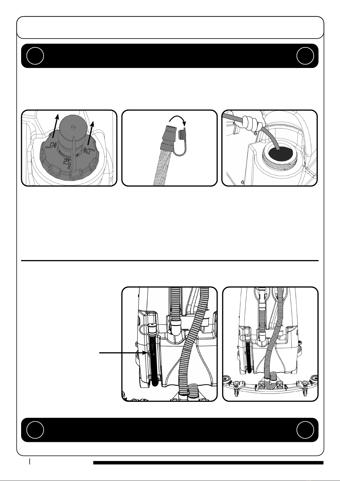
Hose U Bend Clip .................................Page 6
Fitting the Floor tool .................................Page 6
Breakaway Floor tool Feature ..........................Page 6
Raise / Lower Brush Deck................................Page 7
Fitting the brush .................................Page 7
Floor tool Transit Bracket .................................Page 7
Filling the Clean Water Tank ...........................Page 8
Fill Level Indicator ...............................Page 8
Setting the Cleaning Controls .........................Page 9
Waste Water Tank Full .................................Page 9
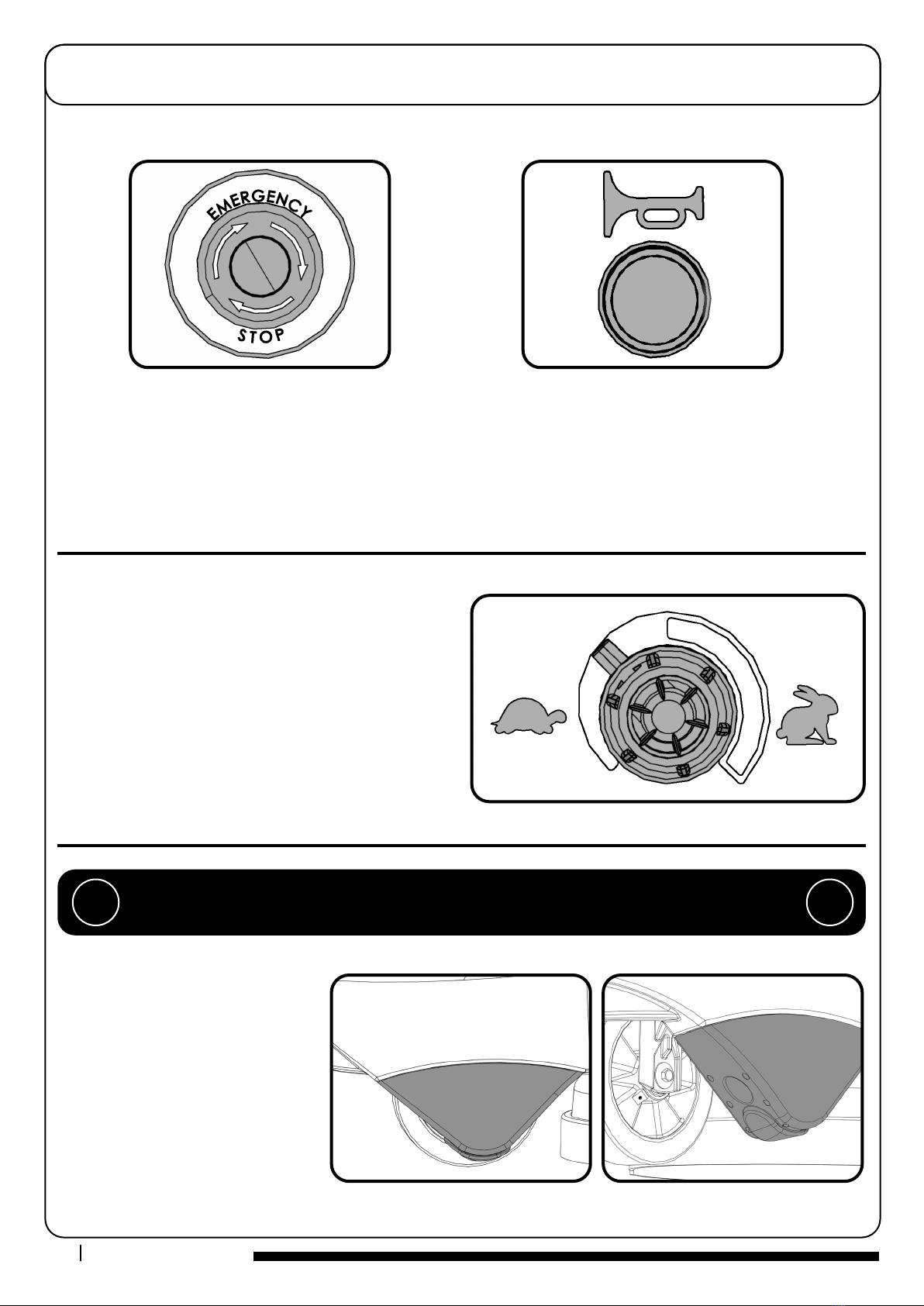
Emergency Stop Button and Horn....................Page 10
Maximum Speed Control .................................Page 10
Anti-tip System .................................Page 10
Machine in Use .................................Page 11
O-aisle Cleaning Kit .................................Page 11
Machine Cleaning .................................Pages 12-13
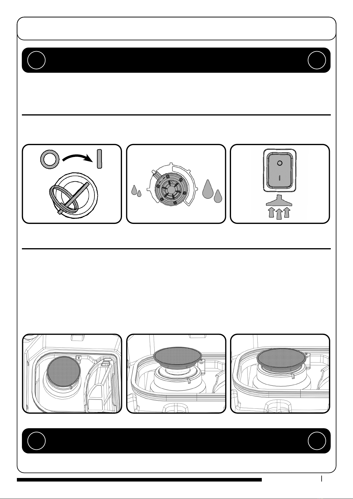
Free-Wheel Function .................................Page 13
Changing Floor tool Blades ..............................Page 14
Machine Charging .................................Page 15
Battery Care .................................Page 16
Charging Lights Sequence ...............................Pages 16-17
Specications .................................Page 18
Trouble Shooting .................................Page 18
Rating Label / Personal Protective Equipment /
Recycling .................................Page 19
Safety Precautions .................................Page 20-21
Recommended Spare Parts ...........................Page 22
Schematic Diagram .................................Page 22
Battery Wiring .................................Page 23
EU Declaration Document ..............................Page 24
Warranty .................................Page 24
Company Address .................................Page 28
RIDE ON SCRUBBER DRYER
Index
After the removal of
all the packaging, carefully open and
check the contents
●Owner Manual
●Battery Charging Lead ● 2 x Keys
●40 Amp Fuse ● 30 Amp Fuse
●20 Amp Fuse ● 10 Amp Fuse
●4 Amp Fuse ● 2.5 Amp Fuse
●Maxi Fuse Puller
PLEASE READ
BEFORE COMMENCING
OPERATION
1 Operator control panel
2 Brush deck foot pedal
3Anti-tip buers
4 Floor-tool raise / lower lever
5Clean water tank ll point
6 Brush deck
7 40 Amp battery fuse
8 Gel batteries
9Clean water tank lter
10 On-board charger and charge indicator
11 Accelerator pedal
12 Pedestrian warning light
13 Floor-tool transit bracket
14 Air separator assembly
15 Waste water emptying hose
16 Vacuum hose
17 Clean water tank emptying hose
18 Floor-tool
19 Safety Fuse (2.5A)
20 Fuse Panel (20A Vac / 30A Brush Motor /
4A Water pump / 10A Brush engage).
TGB 2128/ 2120

6
5
4
19
2
1
3
12
13
14
15
16
10
9
8
7
11
20
Machine Overview
17
18

RIDE ON SCRUBBER DRYER
3
4
5
6
7
8
9
10
2
1 Water Flow Rate 6 Forward / Reverse Switch
2Suction On/O switch 7 Traction LED
3 Brush Engage Button 8 Emergency Stop Button
4 Horn Button 9 Maximum Speed Control
5 Hours and Battery Meter Display 10 Key Ignition Switch
Control Panel Overview
In the event of a breakdown contact
your Numatic dealer or the
Numatic Technical
help line +44 (0)1460 269268
TGB 2120/2128

5
T 01460 68600
Use handle grip when
raising or lowering the
top waste-tank.
Machine Set-up Guide
Note: DO NOT depress accelerator pedal while software initialises. The machine will not operate in reverse with the oor
tool lowered. The seat is tted with a pressure sensor that disables the machine until an operator is seated.
PLEASE READ BEFORE COMMENCING ANY OPERATION AFTER THE REMOVAL OF
ALL THE PACKAGING, CAREFULLY OPEN AND CHECK THE CONTENTS. !!
Turn the key to switch on the
machine, set lever to forward.
Set to slowest speed, depress accelerator and
drive o the pallet using ramp provided.
Once in a safe location switch o machine.
!!
1
2
3
ENSURE THAT NO METAL OBJECTS COME INTO CONTACT WITH BATTERY TERMINALS
WHILE THE BATTERIES ARE EXPOSED.
WHEN INSERTING THE FIRST FUSE YOU MAY NOTICE A SPARK, THIS IS NORMAL.
Less Battery Models - Numatic International Ltd recommends using MK or Sonnenschein Batteries for the 8055 & 8072 machines
mentioned in this manual. For full battery specications see page 22.
Lift top tank assembly to reveal battery
compartment, ensuring you use the
handle grip provided.
Fit battery fuse (contained in start-up
pack) into the battery fuse holder as
illustrated.
(Fig. 1, 2, 3.)
Insert Key into ignition located on the
control panel.
Note: Wear suitable gloves when
inserting fuses.
CONTENTS
● Owner Manual ● Battery
Charging Lead ● 2 x Keys
● 40 Amp Fuse ● 30 Amp Fuse
● 20 Amp Fuse ● 10 Amp Fuse
● 4 Amp Fuse ● 2.5 Amp Fuse
● Maxi Fuse Puller
Fuse

6www.numatic.co.uk
The U-bend in the hose prevents water spillage when the vacuum is switched o.
Ret vacuum hose to the oor tool when nished.
Hose U-bend Clip
Note: DO NOT push the vacuum hose
onto the oor tool with the oor tool
in the raised position.
Machine Set-up Guide
The oor tool design incorporates a safety knock-o feature, this allows it to safely
disengage from its mounting should it become caught on an obstruction during
forward movement.
Make sure you do not over tighten the retaining knobs.
Break-away Floor Tool
Fitting the Floor Tool
Note: Raise oor tool before driving to the cleaning area.
The machine will not operate in reverse with the oor tool lowered.
Lower the oor tool.
Slide oor tool onto bracket. Tighten retaining knobs to nger tight and
attach hose.
Raise the oor tool.

7
T 01460 68600
When tting the brushes make sure it is done on a smooth surface.
To disengage the brush, remove manually.
Note: Do not lift the brush deck until the brush has stopped revolving or the
brush will release.
Make sure you raise the brush deck before driving to the cleaning site.
Safety Gloves are recommended for the changing of used brushes.
When in transit, the oor tool can be placed on the bracket at the rear of the machine.
Simply slot the retaining knob into the bracket.
Machine Set-up Guide
Always ensure that the machine is switched o before making any adjustments. !!
10
11
12
Raise Brush Deck / Fitting the Brush / Lower Brush Deck
Floor Tool Transit Bracket
Raise brush deck. Brush deck raised position. Slide brush under machine.
Brush in place. Lower brush deck. Brush deck lowered.
Press and hold brush engage button.
Switch machine on. Machine has picked up the brush.
Twin Brush
TGB 2128
Please follow the same process to fit both brushes to the TGB 2128 as is for the
single brush fitting on the TGB 2120.

8www.numatic.co.uk
Note: Great care must be taken to ensure that contaminants (leaves, hair, dirt, etc.) are not allowed to enter the clean
water tank during the lling process. If using a bucket or similar, ensure it is always clean and free from debris.
When lling the clean water tank, do not
ll above the clean water tank emptying
hose retaining clip.
This can be found at the rear of
the machine.
Machine Set-up Guide
Always ensure that the machine is switched o before making any adjustments. !!
ll.
Filling the Clean Water Tank
10
Fill Level Indicator
If you need to access the batteries, make sure that the
waste water tank is empty before lifting. !!
To ll clean water tank extend ll hose. Remove rubber seal and ll. Alternatively remove ller cap completely.
The TGB 2120/2128 is equipped with a large capacity 80 litre clean water tank, allowing for large areas to be covered in a single

9
T 01460 68600
Drive the machine to the cleaning site (read set-up guide again if necessary - page 5).
Before cleaning operation, place out appropriate warning signs and sweep or dust-mop the oor.
When ready for cleaning lower the oor tool (page 6) and the brush deck (page 7).
The vac shut o system stops the airow when the top waste water tank is full.
The vac motor will continue to run, there is an audible dierence in the sound when the shut o system operates.
For more details on checking and cleaning the shut o system see page 13.
Machine Operation
IMPORTANT
Do not operate machine unless the operator manual has been read and fully understood. !!
Setting the Cleaning Controls
Waste Water Tank Full
Always ensure that the oor is pre-swept and relevant safety signs are displayed. !!
Open Closed
Switch machine on. Battery charge-level
indicator illuminates.
Set the water ow rate as required. Switch the vacuum motor on.
Low High
H
E
A
V
Y
S
O
I
L
I
N
G

10 www.numatic.co.uk
Note: After the Emergency Stop button has been pressed the Traction LED will ash 7 times, pause and repeat until the
Emergency Stop button has been reset and the machine switched o / on.
The CRG 8055/8072 is equipped with an
Anti-tip system.
The machine automatically slows down
preventing the machine from tipping over if
cornering at speed.
The buers at the front are designed to
prevent the machine tipping in the event of
the operator turning sharply.
The buers are designed to be
replaceable when worn.
Machine Operation
Emergency Stop Button / Horn
Anti-tip System
Set desired traction speed as required, depending on oor type
and level of soiling.
Once the Max speed has been set using the control knob on the
control panel,
ne adjustments can be made using the variable control speed
pedal located on the right side of the footplate.
Maximum Speed Control
Care must be taken to reduce speed when cornering or manoeuvring. !!
In an emergency, strike the emergency
stop to disable the machine.
Horn button - for sounding a warning signal
O
P
T
I
M
U
M
F
L
O
O
R
C
L
E
A
N
I
N
G
T
R
A
N
S
I
T
S
P
E
E
D

11
T 01460 68600
To operate, select forward and depress the accelerator pedal.
Note: The machine will not operate in reverse with the oor tool lowered.
Vacuum pick-up and water ow will turn on if selected, and providing the brush and oor tool are
in the lowered position, the machine will move forward.
Clean water is dispersed evenly via ‘THRU- FEED’ scrubbing brushes.
The waste water is then retrieved by the suction oor tool.
Overlap each scrubbing path by 10cm to ensure an even clean.
After stopping, let the vacuum motor run for 10 seconds to collect any water left in the vacuum
hose, then switch the vacuum motor o.
On heavily soiled oors use a ‘double scrub’ technique.
First pre-scrub the oor with the oor tool in the raised position, allow the chemicals time
to work, then scrub the area a second time with the oor tool lowered.
If your machine leaves streaks on the cleaned oor, either clean the oor tool blade or
adjust blade height for optimum performance.
Machine Operation
Machine in Use
Do not operate the machine on inclines that exceed 11%. !!
The optional o-aisle cleaning kit gives added exibility to the operator.
The kit can be used to clean hard to reach / inaccessible areas.
Remove the vacuum hose from the oor tool and attach to the o-aisle kit.
To operate the vacuum, press the vacuum switch on.
Note: Return the hose to the oor tool once
nished using the o-aisle facility.
Off-aisle Cleaning Kit (Optional Extra Accessory) 606182
Adjusting the blade height.
Set lever to forward.
Water ow rate selection.
Brush deck in lowered position. Floor tool lever in lowered position.
Vacuum switch.
Low
High

12 www.numatic.co.uk
After use, empty waste water tank using emptying hose and ush-out with
clean water.
Remove oor tool vacuum hose ensuring you remove the U-bend clip and ush
out with clean water.
Empty clean water tank, using emptying hose and again ush out with clean
water.
Note: The separator can be hung from either side of the top tank while you maintain the machine using the clip on
the front of the lid.
A
B
C
When retting the separator make sure you engage the front of the separator BEFORE pushing the separator down.
Ret the vacuum hose.
Machine Cleaning
Always ensure that the machine is switched o prior to any maintenance. !!
A
B
C
Remove hose. Remove separator and clean. Clean and examine rubber seal during
each clean.

13
T 01460 68600
Located in your waste water top tank is a vacuum shut o system, this prevents suction when the waste water tank is full. It also
prevents foam created by high-foaming detergents from entering the motor. Sometimes the oat vents get clogged and blocked,
clean to ensure correct operation. Regularly check and clean the air lter in the top of the assembly. Remove debris basket lter
and rinse using clean water, and ret.
IMPORTANT: If the debris basket is allowed to become clogged, vacuum performance can deteriorate.
The clean water tank lter is located to the front of the battery compartment, and should be checked at regular intervals.
Lift the lter o of the cradle, unscrew the bottom and remove, taking care not to spill any liquid on to the batteries.
Rinse using clean water and ret, retting is reversal of removal.
Note: Any Spills should be wiped up before tank is lowered.
Machine Cleaning
Always ensure that the machine is switched o prior to any maintenance. !!
Free Wheel Function
operator to move the machine.
The free wheel lever can be found on the right hand side of the rear axle.
To disengage the brake, pull the lever into the down position.
Re-engage the brake by moving the lever into the up position.
Note: When the brake is disengaged the machine has no braking facility.
Care must be taken when moving the machine in free wheel mode.
ALWAYS ENSURE THAT THE MACHINE IS ON LEVEL GROUND
BEFORE DISENGAGING BRAKE ARM.
NEVER DISENGAGE THE BRAKE WHEN THE MACHINE IS ON A SLOPE / GRADIENT. !!
Debris basket removal.Float vent. Air lter.
Machine shown on it’s side.
The TGB 2120/2128 is equipped with a free wheel function that will enable the

14 www.numatic.co.uk
Changing the Floor Tool Blades
Lower the oor tool then unscrew the retaining knobs and slide it o the holding bracket.
Rinse the oor tool assembly with clean water and ret.
Periodically the oor tool blades should be examined and checked for wear and damage.
Replacement is a reversal of the removal process.
4
2
3
1
5
Floor Tool Overview
1. Retaining pins x 4
2. Rear blade
3. Blade carrier
4. Front blade (slotted)
5. Floor tool main body
Always ensure that the machine is switched o prior to any maintenance. !!
Note: The blades are designed to be
reversible, thus extending their useful
working life.
Remove oor tool. Remove four retaining pins.
Turn the oor tool over. Separate the blade from the carrier. Peel away blades.

15
T 01460 68600
Machine Charging
The large capacity gel batteries are sealed for life and are totally maintenance free.
The on-board charger automatically monitors the charging process and will switch o when the batteries are fully charged.
Note: The charging lead supplied with your machine may dier than the lead shown.
Once the charging lead has been connected the machine will be INHIBITED.
The battery charge indicator display lights will show the current charge state.
Always ensure that the machine is switched o prior to charging. !!
Machine charging point, above footplate. Insert country specic charging lead. Red charging indicator illuminates when
charging.
To ensure a full charge, the machine should be left until the charging indicator shows green.
Once fully charged, disconnect the charging lead from both the power supply and the machine.
Charging indicator (see page 16).
1. The battery meter displays the charge level of the batteries;
when fully charged, all meter lights are illuminated.
2. As the machine is used and the batteries are discharged,
the meter lights will go out from right to left.
3. When the battery meter turns RED the vacuum motor and the brush motor will stop. Once the motors have stopped, turn o the
vacuum motor and lift the brush deck. Turn the key o then back on. If required switch the vacuum motor on to pick up any remain-
ing liquid. Take machine to charging location and place on charge. Ensure the vacuum motor is switched o and the machine is
turned o by the key before charging.
Insert the charging lead required for your country into the charging point.
The machine charging point is located to the rear of the machine under the control panel.
Connect to a suitable power supply.
Once mains power is connected the red charging indicator will illuminate.
To ensure a full charge, the machine should be left for a period of 8 - 10 hrs.
Once fully charged, disconnect the charging lead from both the power supply and the machine.
2
3
1

16 www.numatic.co.uk
Battery Care
To ensure your machine remains at its maximum eciency
and prolong your battery life, please follow the simple steps below: !!
Note: Check machine rating label for correct charger amperage
Charging Light Sequence 10 & 20Amp On-board Charger
Under normal daily usage:
Re-charge the machine FULLY after each use regardless of machine operation
time.
Do not leave the machine in a discharged state.
Periodically inspect the battery connections for tightness and corrosion.
Under abnormal use;
i.e. leaving the machine without charging for a period of time, we advise that you follow
these steps:
If the machine will be standing unused for a period of 30 days or more, then batteries
must be fully charged and battery fuse removed using the maxi fuse-puller provided,
prior to this period.
Batteries should be re-charged every three
months.
Charge fully the day before you start using
the machine again.
Signal (LED) Meaning
Red LED on First Phase (constant current Mode)
Orange LED on Second Phase (Constant Voltage Mode)
Green LED on Third Phase (Constant Voltage Mode) Charge Complete
Red LED ashing
followed by Pause
Charging System Error
Unsuitable battery or charging malfunction, safety timer exceeded,
Internal short circuit, disconnect from power supply, switch power supply,
OFF then ON, to restart the charging cycle
Orange LED ashing Battery not connected
10Amp
Signal (LED) Meaning
Red LED on First Phase (constant current Mode)
Orange LED on Second Phase (Constant Voltage Mode)
Green LED on Third Phase (Constant Voltage Mode) Charge Complete
Red LED ashing
followed by Pause
Cooling Fan Locked > 1 ash between pause
Over Voltage Protection / Output Short Circuit / Battery Reverse Polarity > 2 ashes between pause
Over Temperature Protection > 3 ashes between pause
Charge Time has exceeded 16 hrs during phase 1 or 2 > 4 ashes between pause
20Amp

17
T 01460 68600
Green Status Indicator Fault Possible Cause Eect on Product Investigate the Following Action Required If Fault Persists
1 Flash with pause Batteries voltage low Batteries not been charged Operating time
severely reduced
or machine will not
operate
Check when machine last charged Charge batteries
immediately
Possible bad connection
between batteries, controller,
charger or fuses caused by
loose connections, damaged
wiring, water ingress
Switch OFF the machine :
Remove Fuses
Check connections to batteries, charger and fuses for
loose wires or screws
Tighten loose connections
and replace damaged
components
Not accepting charge due to
faulty battery / cell
Check each battery Voltage individually to detect
defect unit 10.5V min
Replace batteries as re-
quired
Charger not functioning Check battery voltage and charge current ensuring
charger red fault light is extinguished
Replace charger
2 Flashes with pause Traction motor
disconnected
The motor has a bad
connection
The motor will not
operate
Check all connections and leads between motor and
controller
Tighten loose connections
and replace damaged
components
Motor disconnected
TCO activated
(Thermal Cut Out)
Motor failed to open circuit
3 Flashes with pause Traction motor
wiring trip
The motor has a short circuit
to a battery
Motor will not operate Check all connections and leads between the motor and controller
4 Flashes with pause Battery Lockout The battery charge level
has fallen below the
battery lockout level and
the controller is inhibiting
machine functions
Machine functions not
working
Check battery voltage and charge current ensuring
charger red fault light is extinguished
Charge batteries
immediately
Check each battery voltage individually to detect
defect unit 10.5V min
6 Flashes with pause Charger connected The controller is being
inhibited from driving, this
may be because the battery
charger is connected
Machine functions not
working
Remove charger to operate machine
7 Flashes with pause Machine inhibited E-Stop pressed Machine functionality
inhibited
Check E-Stop Release E-Stop and cycle
key switch
8 Flashes with pause Controller trip A controller trip is indicated Machine functions not
working
Check all connections and leads Tighten loose connections
and replace damaged
components
9 Flashes with pause Brake deactivated
or failed
Poor brake connections
Brake failure or deactivation
Traction drive
disabled
Check brake wiring and brake lever Replace brake or wiring as
necessary. Reactivate brake
by engaging brake lever
10 Flashes with pause High battery voltage Poor connections between
battery controller and traction
motor
Machine functions not
working
Check each battery Voltage individually to ensure
voltage < 14 volts
Check connections on controller batteries and traction
motor
Check combined battery pack voltage is < 28 volts
Contact Service Agent

18 www.numatic.co.uk
Trouble Shooting
Failure to rectify the problem or in the event of a breakdown contact your Numatic dealer or
Numatic Technical helpline +44 (0)1460 269268
Model - CRG 8055 / 8072
(Empty) Net Weight
120 A/Hr Brush Weight Brush Width Brush
Pressure
Pad
Width
Pad
Pressure Brush Motor Vac
Motor
CRG 8055 - 200 kg
CRG 8072 - 220 kg
CRG 8055 - 17 kg
CRG 8072 - 32 kg
550 mm
370mm x 2
8.4 G/cm2
19.9 G/cm2
508 mm
360mm x 2
6.8 G/cm2
16.6 G/cm2
24 V
600 W
24 V
400 W
Transaxle Run Time
2 x 120 A/Hr
Run Time
2 x 100 A/Hr
Total Battery
Weight 120 A/Hrs
Total Battery
Weight 100 A/Hrs
Charge Times
2 x 120 A/Hrs
Charge Times
2 x 100 A/Hrs
24 V
400 W 3 Hrs 2 Hrs 74 kg
(163 lbs)
62 kg
(136 lbs)
10A = 12 Hrs
20A = 7 Hrs
10A = 8 Hrs
20A = 5-6 Hrs
Brush Speed Airow Transit Speed Capacity Water Flow Rate Cleaning Area Sound Pressure
150 r/min 24.2 L/sec 0-6 km/h 80L /
80L
0 - 3
L/min
CRG 8055 - 1700m2 @ 3.5 K/Hr
CRG 8072 - 2200m2 @ 3.5 K/Hr ≤ 70dB (A)
Hand Arm Vibration Whole Body Vibration Height Length Width Max Gradient
Travelling (Quarry Tiles)
1.84 m/s2
(Uncertainty 0.92 m/s2)
ISO 5439-1
Travelling (Quarry Tiles)
1.11 m/s2
(Uncertainty 0.56 m/s2)
ISO 2431-1
1160 mm 1460 mm
CRG 8055 - 805
mm
CRG 8072 -
948mm
11%
Specifications
PROBLEM CAUSE SOLUTION
Machine will not operate
Missing or blown fuses
Low battery charge
Machine is connected and charging
Key is o or missing
Handle safety fuse blown
Fit or replace fuse (page 3 & 5)
Charge batteries (page 15 / 16)
Take o charge (page 15)
Insert key & turn to operating position
Replace fuse - No 19 (page 2 / 3) (or contact service engineer)
Vacuum will not operate
Missing or blown fuse
Vacuum switch not engaged
Waste water tank full
Fit or replace fuse (page 3 & 5)
Press switch (page 9)
Empty waste water tank (page 12)
Poor water pick-up
Waste water tank full
Clogged / blocked vacuum hose
Loose hose connections
Debris basket lter clogged / blocked
Separator lter clogged / blocked
Poor separator seal
Damaged separator seal
Damaged / split vacuum hose
Damaged oor tool blades
Low battery charge
Floor tool incorrectly adjusted
Empty waste water tank (page 12)
Remove and clean (page 12)
Push tight connections (page 6)
Remove and clean (page 13)
Remove and clean (page 12)
Clean and ret (page 12)
Renew (contact service dept)
Re-charge batteries (page 15 / 16)
Adjust oor tool (page 11)
No brush / scrub function
No brushes tted
Brush deck raised
Missing or blown fuses
Check and t (page 7)
Lower brush deck (page 7 & 11)
Fit or replace fuse (page 3 & 5)
Little or no water ow
Clean water tank empty
Clean water tank lter blocked / clogged
Water ow not on
Brush deck raised
Blown pump fuse
Fill clean water tank (page 8)
Remove and clean (13)
Switch on water ow (Page 9)
Lower brush deck (page 7 & 11)
Replace fuse - No 20 (page 2 / 3)
Machine just ‘stops’ during
operating
Brush motor fuse blown due to high load
Handle safety fuse blown
Replace fuse & reduce load (page 3 & 5)
Replace fuse - No 19 (page 2 / 3) (or contact service engineer)
Warning Do not t a replacement fuse link having a higher rating than the value stated on the fuse label.

19
T 01460 68600
No HOT drinks
when operating
this machine.
Safety Critical Component:
Charging Leads: Ho5VV-F 3 Core x 1.0 mm2
Transaxle: 205190
Battery Charger: (230V), (115V)
WEEE (Waste, Electrical and Electronic Equipment)
Scrubber dryer Accessories and packaging should be sorted for environmentally-friendly recycling.
Only for EU countries.
Do not dispose of scrubber-dryer into household waste.
According to the European Directive 2002/96/EC on waste electrical electronic equipment and its incorporation
into national law.
Scrubber-dryers that are no longer suitable for use must be separated, collected and sent for
recovery in an environmentally-friendly manner.
Ear Protection Safety Footwear Head Protection Safety Gloves
Dust / Allergens
Protection
Eye Protection Protective Clothing Hi-Vis Jacket Caution
Wet Floor Sign
PPE (Personal protective equipment) that may be required for certain operations.
Note: A risk assessment should be conducted to determine which PPE should be worn.
CAUTION
Rating Label
1 Company Name & Address
2 Machine Description
3 Power rating
4 Voltage Frequency
5 Max Gradient
6 Approvals Mark
7 WEEE Logo
8 Weight (ready to use)
9 Ingress Protection Rating
10 Machine yr/wk Serial number
11 Machine Description
12 Noise Rating
13 Hand Arm Vibration
About the Machine
1
2
3
4
8
5
6
9
10
7
11
12
13

20 www.numatic.co.uk
Information for Scrubber Dryer
As with all electrical equipment care and attention must be exercised at all times during its use, in addition to ensuring
that routine and preventative maintenance is carried out periodically in order to ensure its safe operation.
Failure to carry out maintenance as necessary, including the replacement of parts to the correct standard could render
this equipment unsafe and the manufacturer can accept no responsibility or liability in this respect.
When ordering spare parts always quote the Model Number / Serial Number specied on the Rating Plate.
This appliance is not intended for use by persons (including children) with reduced physical, sensory or mental capabilities, or lack
of experience and knowledge, unless they have been given supervision or instruction concerning use of the appliance by a person
responsible for their safety.
Children should be supervised to ensure that they do not play with the appliance.
If this product does not have a factory installed Numatic battery charger and batteries then it is the responsibility of the owner and
user of the product to ensure that the charging system and battery combination are compatible, t for purpose and safe to use.
Only use brushes provided with the appliance or those specied in the instruction manual.
The use of other brushes may impair safety.
A full range of brushes and accessories are available for this product.
Only use brushes or pads which are suitable for the correct operation of the machine for the specic task being performed.
It is essential that this equipment is correctly assembled and operated in accordance with current safety regulations.
When using the equipment always ensure that all necessary precautions are taken to guarantee the safety of the operator and any
other persons who may be aected.
Wear non-slip footwear when scrubbing. Use a respiratory mask in dusty environments.
The machine, while charging, must be positioned so that the mains plug is easily accessible.
Remove the key from the ignition when cleaning and carrying out routine maintenance.
In order to prevent unauthorized use of the machine, the power source shall be switched o or locked, for example by removing the
key of the main switch or the ignition key.
When replacing major components the ignition key and battery fuses MUST be removed.
If this product does not have a factory installed Numatic battery charger and batteries then it is the responsibility of the owner and
user of the
product to ensure that the charging system and battery combination are compatible, t for purpose and safe to use.
Machines left unattended shall be secured against unintentional movement.
When detergents or other liquids are used, read the manufacturer’s instructions.
Operators shall be adequately instructed as to the correct use of the machine.
This machine is not suitable for picking-up hazardous dust.
Do not use on surfaces having a gradient exceeding that marked on the appliance.
The machine is not to be stored outdoors in wet conditions.
This machine is for indoor use only.
Read the instruction manual before using the appliance.
This product meets the requirements of BS EN / IEC 60335-2-72.
NOTE: This machine is also suitable for commercial use, for example in hotels, schools, hospitals, factories, shops and
oces for other than normal housekeeping purposes.
• Ensure only competent persons unpack/assemble the machine.
• Keep your machine clean.
• Keep your brushes in good condition.
• Replace any worn or damaged parts immediately.
• Regularly examine the power cord for damage, such as cracking or ageing. If damage is found, replace the cord
before further use.
• Only replace the power cord with the correct Numatic approved replacement parts.
• Ensure that the work area is clear of obstructions and / or people.
• Ensure that the working area is well illuminated.
• Pre-sweep the area to be cleaned.
• Use steam cleaners or pressure washers to clean the machine or use in the rain.
• Attempt machine maintenance or cleaning unless the power plug has been removed from the supply outlet,
if the machine is in charge mode or remove the key if in normal use.
• Allow any inexperienced repairs. Contact your nearest service centre.
• Strain charger lead or try to unplug by pulling on charger lead.
• Leave the brush deck in the lowered position when not in use.
• Expect the machine to provide trouble-free, reliable operation unless maintained correctly.
• Run the machine over any power cables during operation.
WARNING
CAUTION
DO
DON’T
ORIGINAL INSTRUCTIONS
READ MANUAL BEFORE USE
This manual suits for next models
1
Table of contents
Popular Dryer manuals by other brands

Whirlpool
Whirlpool YLER4634EQ2 installation instructions

Beko
Beko EDF95243CSH2A user manual

Fisher & Paykel
Fisher & Paykel DH9060FS installation guide

Podab
Podab ProLine FC 20 Service manual and spare parts list

Bosch
Bosch WTN84200AU Installation and operating instructions

XPower
XPower B-8 owner's manual