. . .
::~
.~:::..
-=-.:.
:!'i·,;
*f.:!'&~·~·...,;tlli:f'.
r: t
?t"tr
!Tet'ti?!'f:
1
.!
5.
If
within
turn-on tolerances,
allow
unit
to
warm
up
for
5 minutes.
The voltage should then
be
30
mV,
tolerances± 10mV.
IF
NOT
WITHIN
TOLERANCES
GO
TO ADJUSTINGI
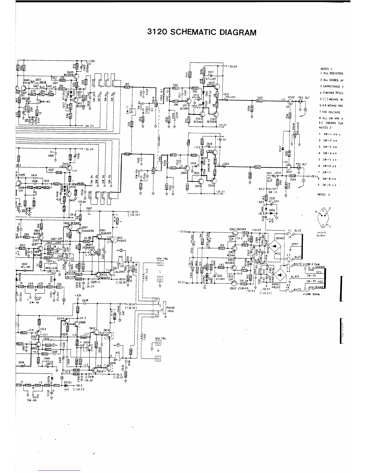
6.
If
0
K,
reconnect the soldershorts
across
R 653 and R 654.
Adjusting:
7.
Turn
off,
remove
bias
adjusting resistors RX 1 (left) and
RX
2 (right) and temporary replace
with
variable resistors 2 Kohms
to
5 Kohms,
set
the variable resistors
to
maximum resistance.
8.
Turn
on and read voltage
acress
R 653 and R 654.
It
should
be
less
than 10 mV.
If
too
high,
turn
off
unit
immediately and check the
output
amplifier
section, especially
0609-0611-
0613-0615-0617
left
channel
or
0610-0612-0614-0616-0618
right
channel.
9.
If
voltage
is
0 K upon
tum-on,
adjust variable resistors
to
read
approximately
12
mV
on VOM.
Leave
unit
on
for
5 minutes and reset voltage
to
30
mV. Note
that
it
takes a
little
time
for
readings
to
stabilize.
10.
Turn
off
and remove variable resistors and replace
with
fixed
resistance
with
exatly the
same
measured value.
Use
resistors in
series
or
paralell
if
necessary.
11. Recheck idling current.
12. Reinstall soldershorts
across
R 653 and R 654.
ALIGNMENT
INSTRUCTIONS
(continued)
Notes:
1.
Failure
to
re-install soldershort
across
R653 and R 654
will
result in failure
at
high volume.
2.
Decreasing value
of
RX 1 and RX 2
will
cause
idling current
to
increase.
3.
Too
little
idling current
will
cause
"Crossouer" distortion.
Too
much
idling
current
will
result
in overheating.
8
DC
OFFSET:
1.
Set
Volumecontrol
to
minimum,
disconnect any outputloads.
2.
Connect DMM
or
VOM across
each
channel's speaker terminals.
3.
Turn
on and read VOM. Reading should
be
0
V.
DC.
Tolerance±
50mV.
Adjust
VR 5 {left)
or
VR 6 (right)
as
necessary.
Notes:
1.
Before adjusting
VR
5
or
VR
6 soften the lock paint
with
laquer
thinner
to
avoid destroying
them. Secure
with
lock
paint
(nail polish) when adjustment
is
completed.
2.
Incorrect adjustment
of
DC
offset
can
create pop when inserting/removing Headphone plug.
"T
3. Offset more than 3 V
is
caused
by
defective parts,
not
by misadjustments.
For
Service Manuals
MAURITRON SERVICES
8
Cherry
'free Road,
Chinnor
Oxfordshlre, OX9
4QY.
Tel
(01844)
351694
Fax(01844)
3~2554
(