3/15 IOM-SDTU
Installation and Operation Manual
Single Du t Terminal Units
Nailor Industries Inc. reserves the right to change any information concerning product or specification without notice or obligation.
Page 1 of 4
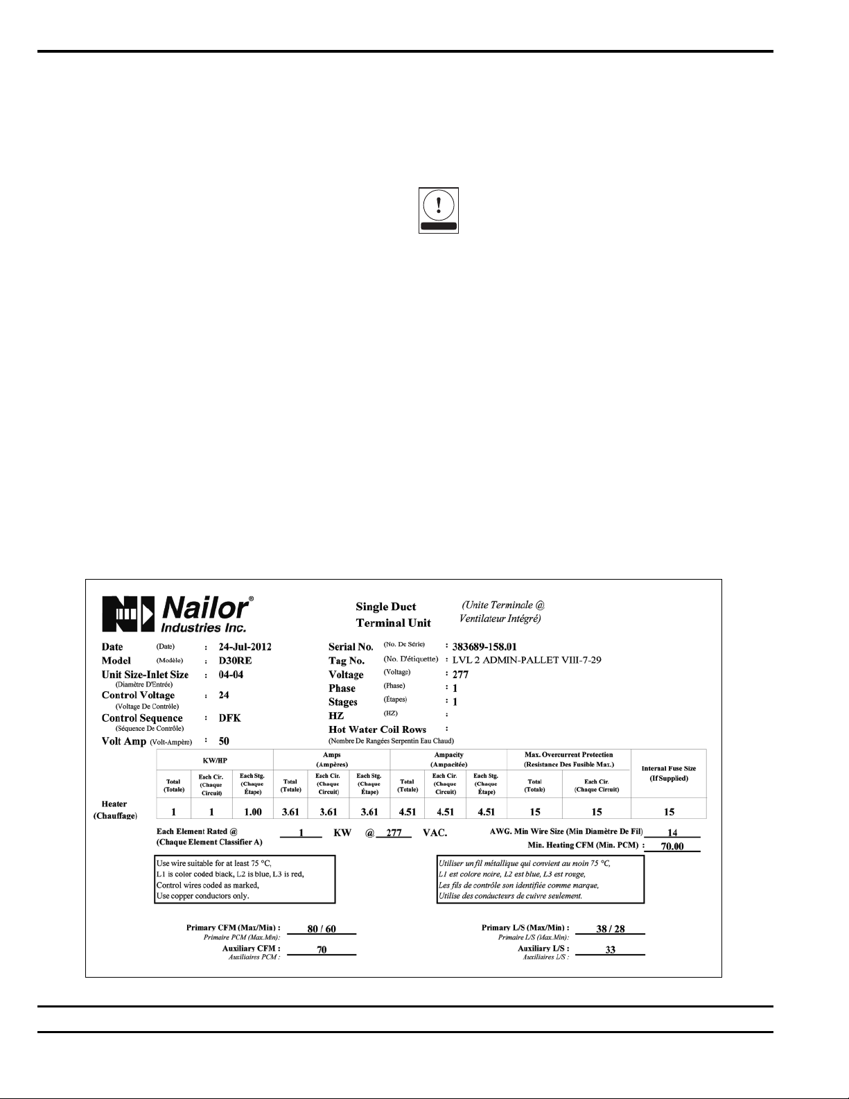
Re eiving Inspe tion
After unpacking the assem ly check it for
shipping damage. If any shipping damage is
found, report it immediately to the delivering
carrier. During unpacking and installation do
not handle y the inlet velocity sensor or the
control package.
Determine Position of the
Control En losure
The control enclosure can e installed on
either side of the ductwork y flipping the VAV
unit over 180 degrees. Unit with mercury
contactors, pneumatic controls, and digital
controls (DDC) need to e inspected efore
installing.
Important: Unit with mercury contactors is
position sensitive. As a result, efore installing
unit with mercury contactors, inspect the
position of the mercury contactors in the
control enclosure. Mercury contactors must e
heading up 90 degrees vertically. If they are
heading down, unscrew the mercury contactors,
rotate 180 degrees, and reinstall them.
If unit is equipped with pneumatic controls, it
should e mounted right side up and level
within ±10 degrees of horizontal, and parallel to
the airflow. The first letter in the model num er
indicates control type (P is for pneumatic). If
the unit is mounted upside down, the controller
will have to e repositioned, re-piped, and
recali rated. Analog control units (A-analog
model num er pre-fix) may e installed in any
orientation. Some Digital (DDC) controls
(D-digital model num er pre-fix) are position
sensitive dependent on the airflow sensor
transducer. Check with the controls
manufacturer for verification.
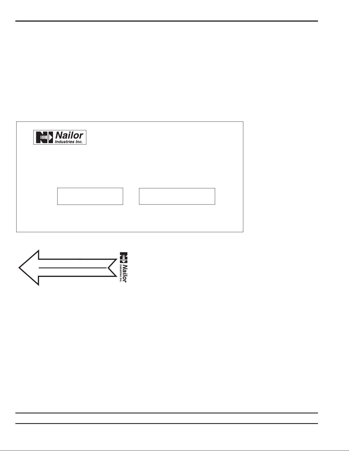
Supporting the Assembly
We recommend that each terminal unit e
independently supported, especially when
accessory modules, such as coils, attenuators,
silencers or multiple outlets are present.
Hanger straps may e used and screwed
directly into the sides or ottom of the unit
casing (see Fig. 1). Alternately, a carriage
made of unistrut may e used, somtimes this is
known as a trapeze setup. Support the VAV
and any accessories separately (Fig. 2). When
requested, unit is supplied with field mounted
hanger rackets for use with hanger rod up to
3/8" (9.5) dia. Hanger rackets should e
screwed into the top of the unit casing (see Fig.
3 & 4). Use the support method prescri ed for
the rectangular duct in the jo specifications.
CONTROL
ENCLOSURE
INLET
OPTIONAL HANGER BRACKET
(FIELD LOCATED
& INSTALLED)
RECTANGULAR
DISSIPATIVE SILENCER
SLIP & DRIVE
CONNECTION
COIL
SECTION
COMPRESSION STRAP ON FLEXDUCT
TO ENSURE AIRTIGHT JOINT
OPTIONAL
ACCESS DOOR
CONTROL
ENCLOSURE
RECTANGULAR
DISSIPATIVE SILENCER
SLIP & DRIVE
CONNECTION
COMPRESSION STRAP ON FLEXDUCT
TO ENSURE AIRTIGHT JOINT
CONTROL
ENCLOSURE
INLET
SLIP & DRIVE
CONNECTION
COMPRESSION STRAP ON
FLEXDUCT TO ENSURE
AIRTIGHT JOINT
OPTIONAL
ACCESS DOOR COIL
SECTION
RECTANGULAR
DISSIPATIVE
SILENCER
SLIP & DRIVE
CONNECTION
ACCESS
DOOR VAV
SECTION
DISCHARGE
DUCT
INLET
DUCT
CONTROL
ENCLOSURE
SLIP & DRIVE
CONNECTION
OPTIONAL HANGER BRACKET
(FIELD LOCATED & INSTALLED)
METAL STRAP HANGERS
SECURED TO BUILDING STRUCTURE
INLET 5/16" OR 3/8" (8 OR 10) DIAMETER HANGER RODS
SECURED TO BUILDING STRUCTURE
MINIMUM 2 DUCT DIAMETERS
OF STRAIGHT DUCT
ON AIR TERMINAL INLET
MINIMUM 2 DUCT DIAMETERS
OF STRAIGHT DUCT
ON AIR TERMINAL INLET
MINIMUM 2 DUCT DIAMETERS
OF STRAIGHT DUCT
ON AIR TERMINAL INLET
DISCHARGE
DUCT
DISCHARGE
DUCT
DISCHARGE
DUCT
Figure 1: Support Using Hanger Straps (Shown: Model D30RW - Single Du t VAV
Terminal Unit with Hot Water Heat).
Figure 2: Support Using Unistrut and Rods (Shown: Model 3001Q - Single Du t
Terminal Unit with Dissipative Silen er).
Figure 3: Support Using Optional Supplied Hanger Bra kets (Shown: Model
D30RWQ - Single Du t VAV Quiet Terminal Unit with Standard Dissipative
Silen er and Hot Water Heat).
Figure 4: Support Using Optional Supplied Hanger Bra kets (Shown: Model
D30HQX - Single Du t VAV Exhaust Terminal Unit with Dissipative Silen er).