Nailor Industries Inc. reserves the right to change any information concerning product or pricing without notice.
SCHEDULE TYPE:
PROJECT:
ENGINEER:
CONTRACTOR:
Page 1 of 1.
Dimensions are in inches (mm)
DATE B SERIES SUPERSEDES DRAWING NO.
3 - 18 - 18 3000 10 - 28 - 16 D30HQW
SINGLE DUCT TERMINAL UNIT WITH HOT WATER
REHEAT AND DISSIPATIVE SILENCER
HOSPITAL GRADE • SUPER QUIET
DIGITAL CONTROLS • VARIABLE OR CONSTANT VOLUME
MODEL: D30HQW
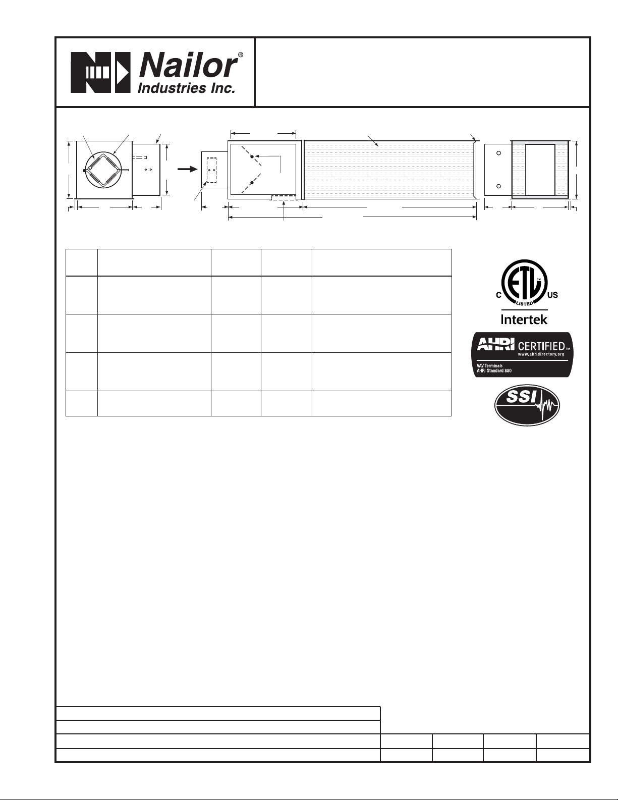
5 1/2"
(140)
OPTIONAL
ACCESS DOOR
H
DAMPER
DRIVESHAFT
L
W
W6"
(152)
11"
(279)
H
15 1/2" (394)
63 1/2" (1613)
14" (356)
48" (1219)
AIRFLOW
OPTIONAL
FMI
REMOVABLE
FLOW SENSOR
FOR FACTORY MOUNTED
CONTROLS
AVERAGING
FLOW SENSOR
6"
(152)
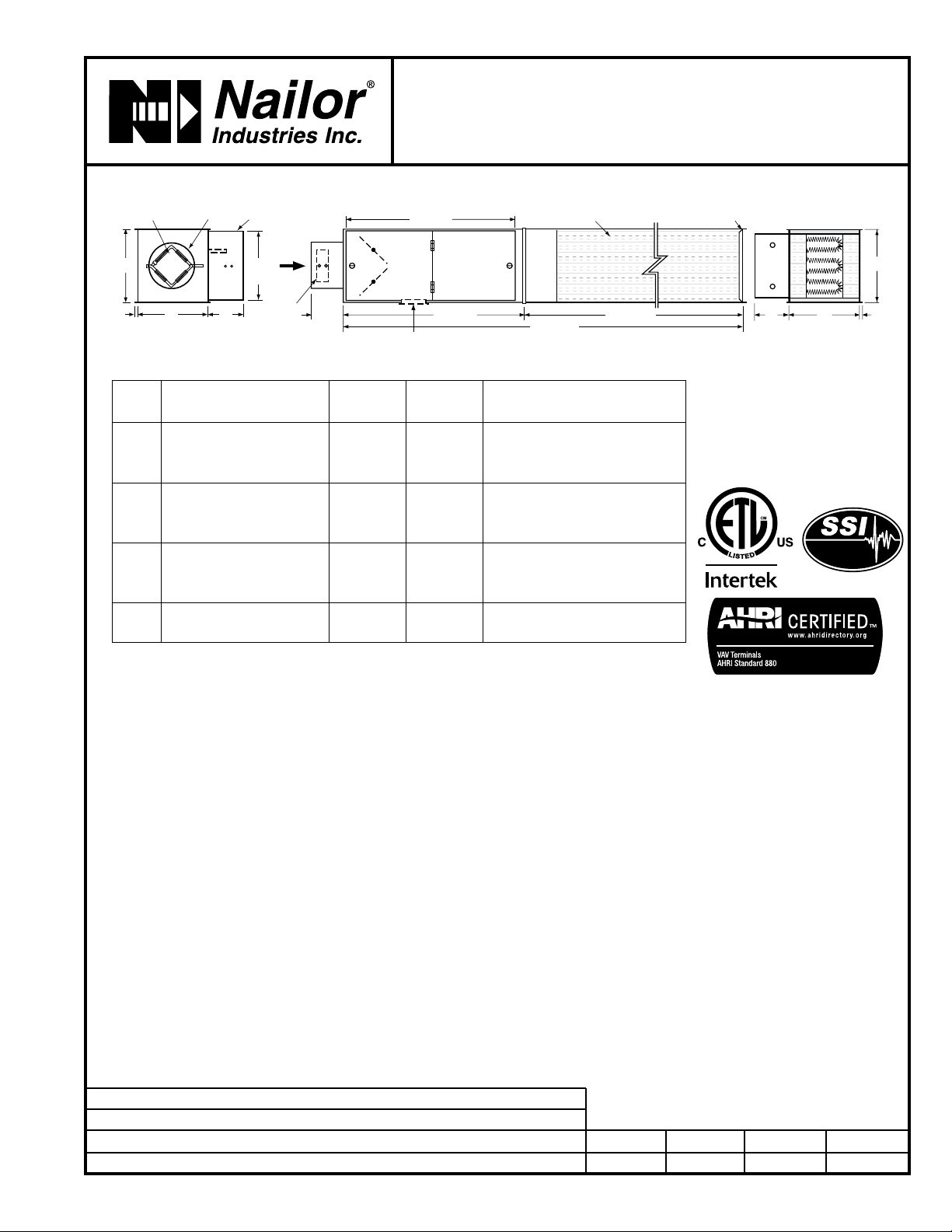
RECTANGULAR DISSIPATIVE
MYLAR LINED SILENCER
SLIP AND DRIVE
CONNECTION
FLAT OVAL OR
RECTANGULAR
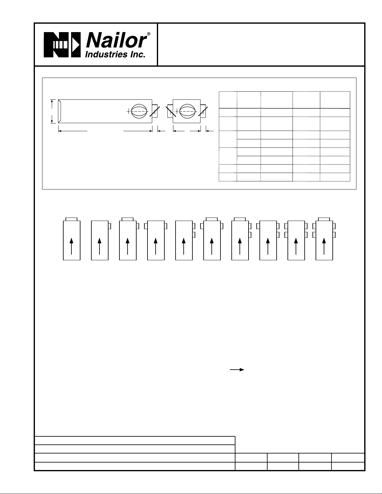
Dimensional Data
Standard Features:
• Designed for hospital and other critical
environment applications where IAQ is a
concern.
• 22 ga. (0.86) zinc coated steel casing,
mechanically sealed, low leakage
construction.
• 16 ga. (1.63) corrosion-resistant steel
inclined opposed blade damper with
extruded PVC seals (single blade on size
4, 5, 6). 45O rotation, CW to close. Tight
close-off. Damper leakage is less than 2%
of the terminal rated airflow at 3" w.g. (750 Pa).
•1/2" (13) dia. plated steel drive shaft.
An indicator mark on the end of the shaft
shows damper position.
• Multi-point averaging Diamond Flow
Sensor. Aluminum construction. Supplied
with balancing tees.
• Rectangular discharge with slip and
drive cleat duct connection.
• Full NEMA 1 type controls enclosure for
factory mounted controls.
• VAV section is lined with 13/16" (21),
thick, 4 lb. density Steri-Liner insulation.
Fiberglass with a reinforced aluminum
FSK facing. Meets the requirements of
NFPA 90A, UL 181 and ASTM C655.
"Notch and tuck" fabrication and full seam
length steel Z-strip construction.
• Right-hand controls location is standard
(shown) when looking in direction of
airflow. Optional left hand controls
mounting is available.
Silencer Section:
• Designed to mate with VAV section for
optimum performance and super quiet
operation.
• Optimized internal baffle geometry
reduces self-generated noise, minimizes
pressure drop and maximizes acoustic
attenuation.
• 22 ga. (0.86) coated steel perforated
baffles encapsulate fiberglass acoustic
media. Mylar lining with acoustical spacer
isolates material from airstream.
• Internal Steri-Liner insulation on top and
bottom optimizes sound reduction and
eliminates need for external field applied
thermal duct wrap.
Hot Water Coil Section:
• 1/2" (13) Copper tubes and aluminum
ripple fins, 10 per inch.
• 20 ga. (1.00) zinc coated steel casing
Uninsulated.
• Left or right hand connection. Determined
by looking in direction of airflow (RH
illustrated).
• 1/2" (13), 7/8" (22) or 1 3/8" (35) O.D.
male solder sweat connections.
Digital Controls:
qNailor EZvav.
qFactory mount (by others).
qField mount.
See separate submittal.
Options and Accessories:
q Bottom access door.
qFMI Removable insert type Diamond
Flow Sensor.
q24 VAC control transformer.
qToggle disconnect switch.
qHanger brackets.
qControls enclosure for field mounted
controls.
qDust tight enclosure seal.
Seismic Certification:
qSSI (Standard)
qOSHPD
qSpecial Features: ______________ .
DIMENSION "L"
1 or 2 row coils L=5" (127)
3 or 4 row coils L=7 1/2" (191)
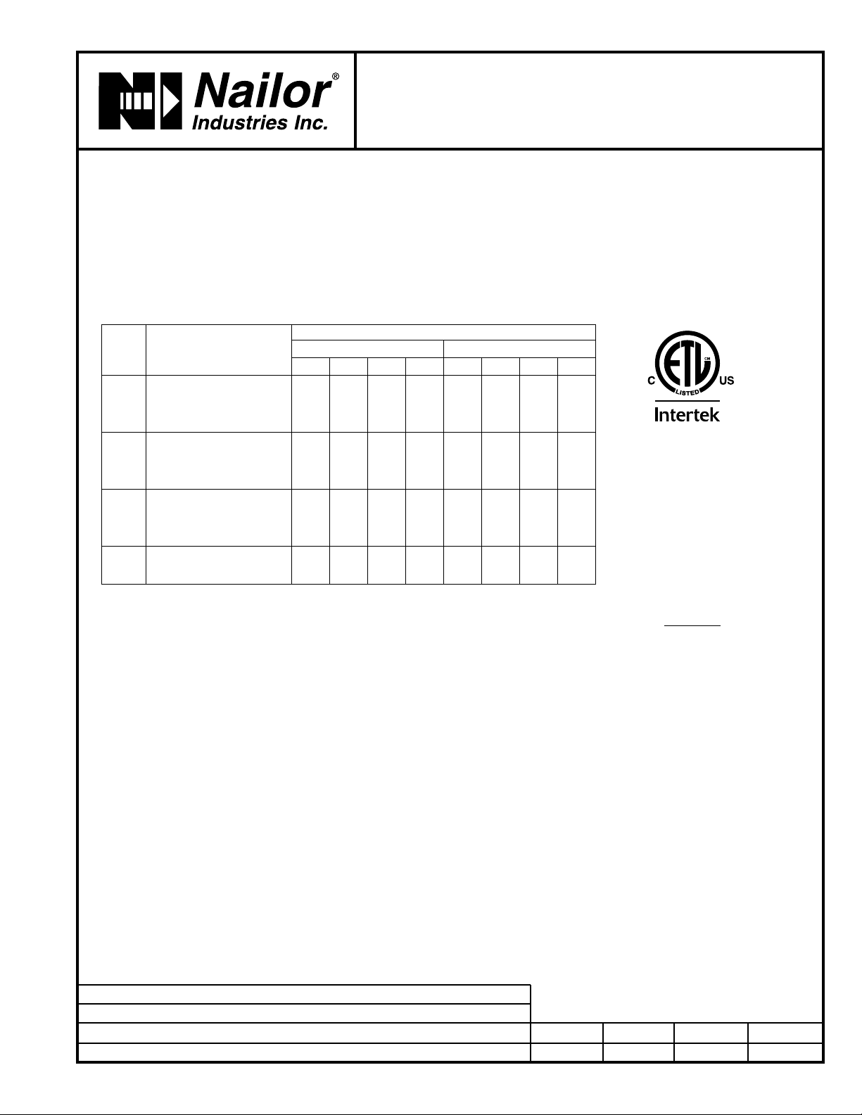
*Maximum airflow limit is based upon 1.5" w.g. (373 Pa) max. differential pressure signal from Diamond Flow Sensor.
Unit
Size
Airflow Range*
cfm (l/s) W H Inlet Size Coil Connections
1 Row 2 Row 3 Row 4 Row
40 – 225 (0 – 106) 10 (254) 10 (254) 3 7/8 (98) Round 1/2 (13) 7/8 (22) 7/8 (22) 7/8 (22)
50 – 400 (0 – 189) 10 (254) 10 (254) 4 7/8 (124) Round 1/2 (13) 7/8 (22) 7/8 (22) 7/8 (22)
60 – 550 (0 – 260) 10 (254) 10 (254) 5 7/8 (149) Round 1/2 (13) 7/8 (22) 7/8 (22) 7/8 (22)
70 – 800 (0 – 378) 12 (305) 12 1/2 (318) 6 7/8 (175) Round 1/2 (13) 7/8 (22) 7/8 (22) 7/8 (22)
80 – 1100 (0 – 519) 12 (305) 12 1/2 (318) 7 7/8 (200) Round 1/2 (13) 7/8 (22) 7/8 (22) 7/8 (22)
90 – 1400 (0 – 661) 14 (356) 12 1/2 (318) 8 7/8 (225) Round 1/2 (13) 7/8 (22) 7/8 (22) 7/8 (22)
10 0 – 1840 (0 – 868) 14 (356) 12 1/2 (318) 9 7/8 (251) Round 1/2 (13) 7/8 (22) 7/8 (22) 7/8 (22)
12 0 – 2500 (0 – 1180) 18 (457) 12 1/2 (318) 12 15/16 x 9 13/16 (329 x 249) Oval 1/2 (13) 7/8 (22) 7/8 (22) 7/8 (22)
14 0 – 3125 (0 – 1475) 24 (610) 12 1/2 (318) 16 1/16 x 9 13/16 (408 x 249) Oval 1/2 (13) 7/8 (22) 7/8 (22) 7/8 (22)
16 0 – 3725 (0 – 1758) 28 (711) 12 1/2 (318) 19 3/16 x 9 13/16 (487 x 249) Oval 7/8 (22) 7/8 (22) 7/8 (22) 7/8 (22)
24 x 16 0 – 8330 (0 – 3931) 38 (965) 18 (457) 23 7/8 x 15 7/8 (606 x 403) Rect. 7/8 (22) 7/8 (22) 1 3/8 (35) 1 3/8 (35)
Listed