§
~
y /;J$iWJO)
~'ii~···········
2
1Y!ffl_LO)
~'j_£~.......................
2
1.
ft
**................................... 2
2.
;J$i1W
0)
~11m·············
...
·
..
·
..
··
..
· 3
2-1
~
~
;;-
O)w
X.1t
~
t ·······.......·
..
·· 3
2-2 .:c-
-7-
t
O);J"f~··.
....
..
..
.
..
..... 3
2-3
~lliiiO)Jfl{t~t········
..
·····
..
····· 3
2-4 rwll: ·
J:.f~JJ:O)~~.............
4
3
.1Y!ffl
_t
0)
~'ii
~.......................
4
3-1
IE
1W····
..
···
..
·········
..
·····
.........
4
3-2
tP
i
O)*ftrm~~··
...................... 4
3-3
~Jv
~
7J
J'\'-O)Jf~1·J't
............... 5
~~y/0)1Y!v)7J
.......................
5
4-1
~tO)J&1t~t1J···......................
5
4-2
r
*0)~
~
1J......................... 6
4-3
J:.*'O)illi
L1J......................... 6
4-4
~~"'13ft~
O)~~n
c
~
L~"'....
7
4-5
*'
~
.::;............................. 7
4-6
J:.*~~:t.J
O)il~..
.................... 7
4-7
r
*~~:t.J
0)~~......
................
8
4-8
*'If~
~
){;f,............................ 8
4-9
w
X.J±:t.J
O)~Ji('j..
...
....
..
..
..
..
.
....
8
4-1o
~tc
n70)001*...................... 8
4-11
J2S
~
lljtj
~
............................ 9
4-12 w
X.JE
c
..till~
)EO)f1!!li1JjWj
~
.... 9
4-13
~
X.JE
c
J:.m
~
JEO)~li..t
r
ill!w1Ji11:
9
~~4-14
~tt~t~!tJJaO)wH~f)]:·tiO)~~·...
10
4-15
~*
~
7
7~
;f,
")
~
O){)i:m;:..........
10
4-16
1m
!l!i
;e
.7..
0)
:fJJ
WH~
·mt
..
•............· 1o
4-17
*W
tJ
-71
~;;-~f
...................
11
4-18
*'W
tJ
O)¥!fi1J1Ji~·
..
....·......·....
11
4-19
;e
7-.0)x~
............................
11
4-20
1mW1*~-r............................
12
4-21 ;(
7-.J±O)j,mj~
.........................
12
4-22
~"'13ft~
glj~"'~J!t-~ilil<
....
12
5.,%W
~
~:.B~t;:,JJ.~t
)Jj{
129
•
:k'.t
~...............................
13
6.ffi
JJJt
:g:~
&=6
..
..
..
..
.
..
.
..
..
....
..
.
....
.
..
...
..
14
6-1
~
~
;;-tfB~
.............................
14
6-2
)'~-
·:;
1)
.7..
~
..........................
18
CONTENTS
page
CAUTIONS
BEFORE
OPERATING
THE
MACHINE
.......
2
CAUTIONS
WHEN
OPERATING
THE
MACHINE
..........
2
1.
SPECIFICATION
.............................................................
2
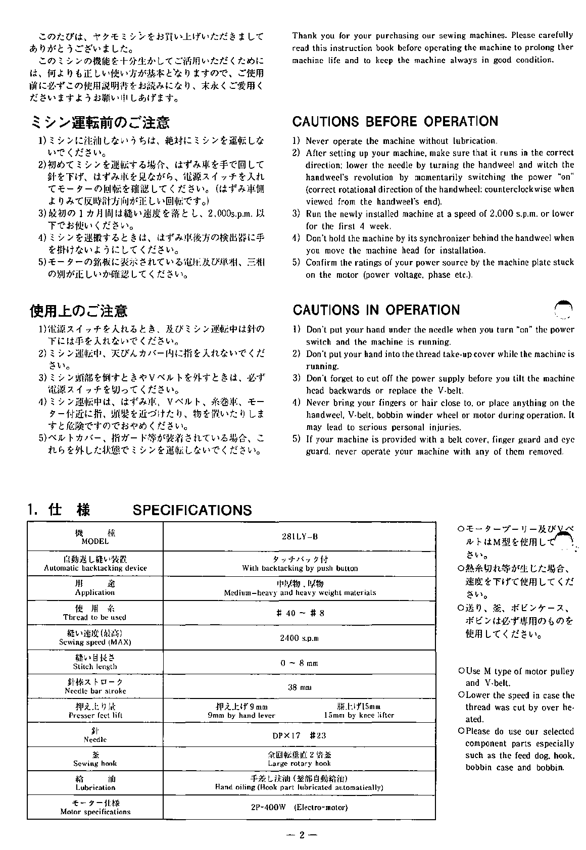
2.
PREPARATION
BEFORE
OPERATING
THE
MACHINE
................................................................
3
2-1
SETTING
UP
THE
MACHINE
................................................ 3
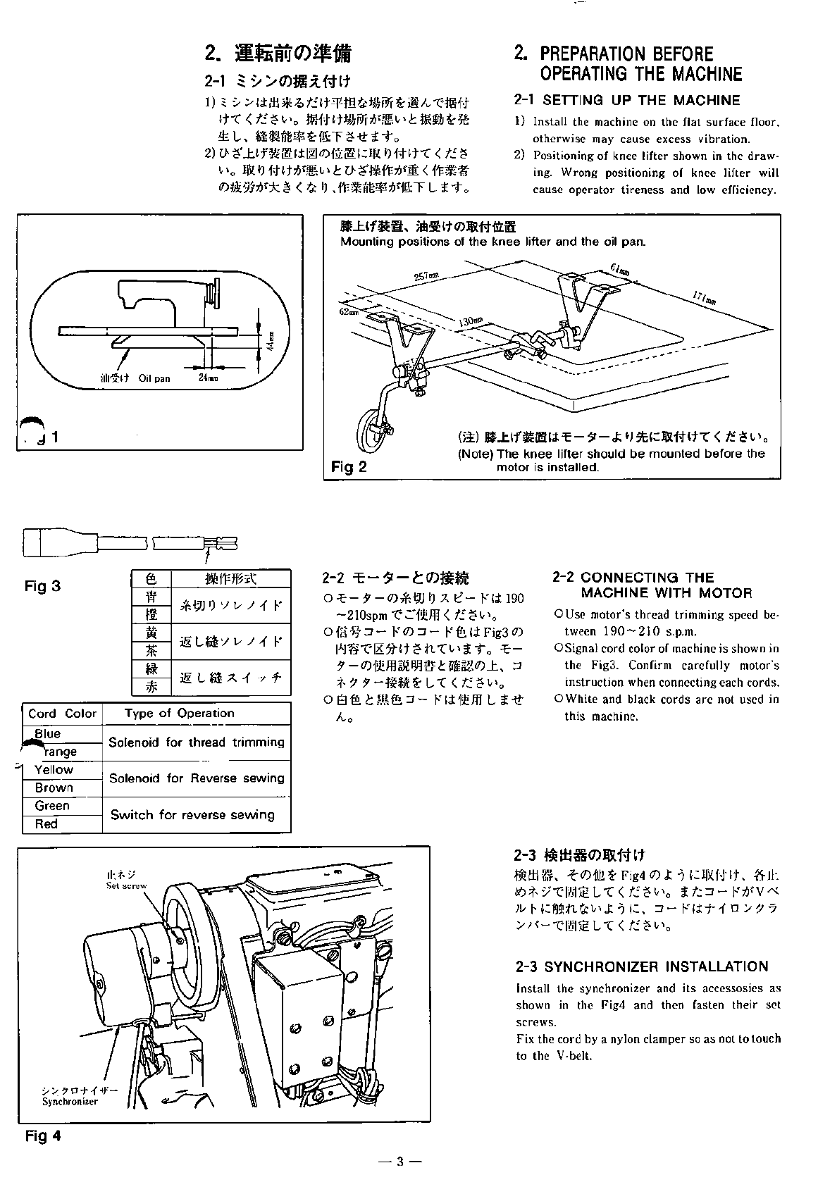
2-2
CONNECTING
THE
MACHINE
WITH
MOTOR
.......................... 3
2-3
SYNCHRONIZER
INSTALLATION
.......................................... 3
2-4
UPPER
AND
LOWER
NEEDLE
STOPPING
POSITIONS
............... 4
3.
CAUTION
IN
USE
..........................................................
4
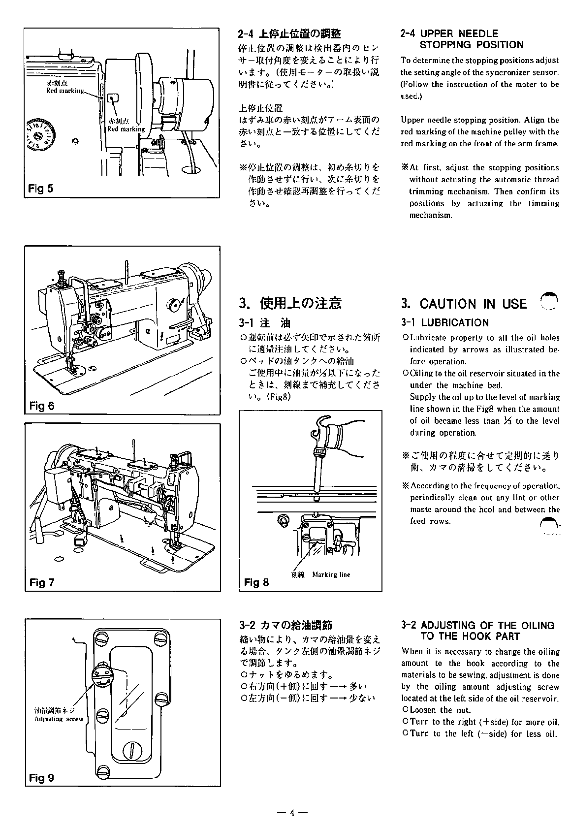
3-1
LUBRICATION
................................................................... 4
3-2
ADJUSTING
OF
THE
OILING
TO
THE
HOOK
PART
.................. 4
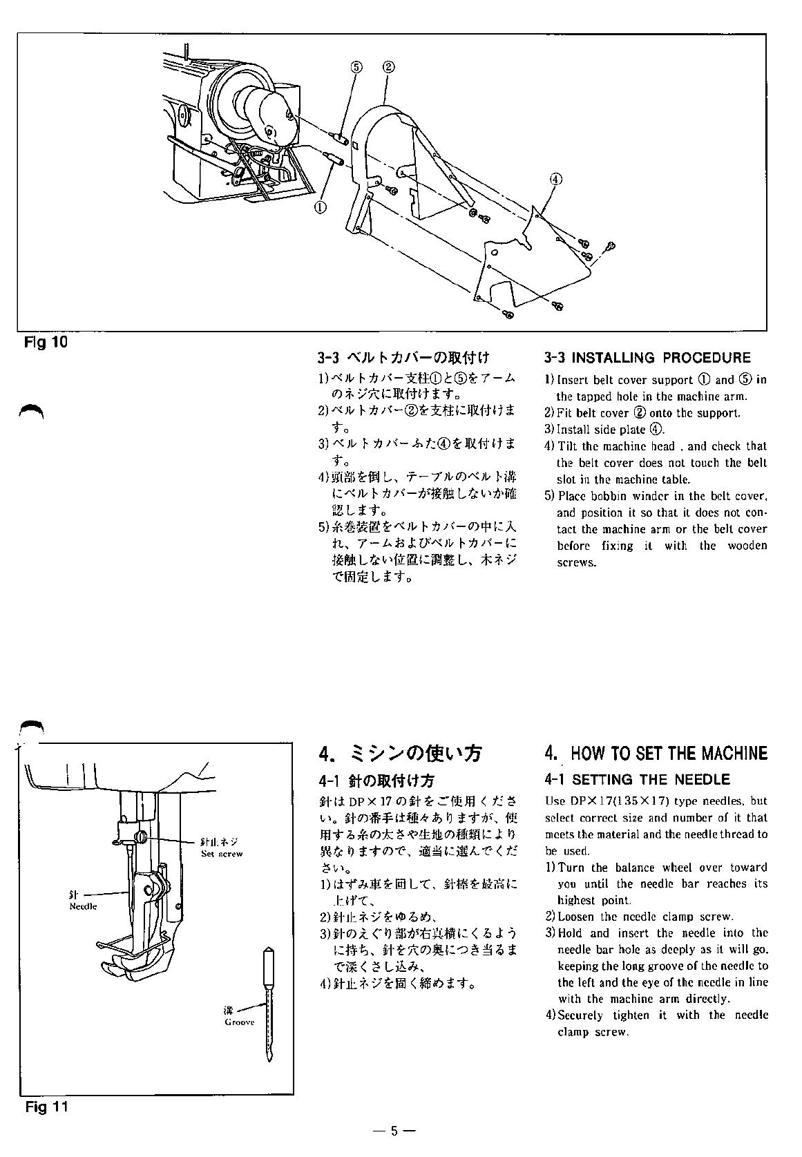
3-3
INSTALLING
THE
BELT
COVER
..
·....·....·......·....·
..
·....·.......... 5
4.
HOW
TO
SET
THE
MACHINE
..................................
5
4-1
SETTING
THE
NEEDLE
....................................................... 5
4-2
WINDING
THE
BOBBIN
THREAD
.......................................... 6
4-3
THREADING
THE
UPPER
THREAD
....................................... 6
4-4
ADJUSTING
THE
STITCH
LENGTH
AND
REVERSE
FEED
......... 7
4-5
THREAD
TENSION
............................................................. 7
4-6
THE
NEEDLE
THREAD
TENSION
.......................................... 7
4-7
ADJUSTING
THE
BOBBIN
THREAD
TENSION
......................... 8
4-8
THREAD
TAKE
UP
SPRING
................................................. 8
4-9
ADJUSTING
THE
PRESSER
OF
PRESSED
FOOT
....................... 8
4-10
TIMING
OF
NEEDLE
AND
ROTATING
HOOK
.......................... 8
4-11
ADJUSTING
THE
HEIGHT
OF
FEED
DOG
............................... 9
4-12
ADJUSTING
THE
HEIGHT
OF
PRESSER
FOOT
AND
FEEDING
FOOT
·................·....·....·................·
..
·
..
·
..
·.... 9
4-13
ALTERNATE
STROKE
AMOUNT
OF
PRESSER
FOOT
AND
FEEDING
FOOT
..................................· 9
4-14
ADJUSTING
THE
LONGITUDIAL
POSITION
OF
THE
NEEDLE
BAR
FRAME
.............................................
10
4-15
POSITION
OF
THE
REVERSE
FEED
SOLENOID
.......................
10
4-16
HOME
POSITION
OF
THE
ROTARY
KNIFE
.............................
10
4-17
ADJUSTING
THE
THREAD
TRIMMING
CAM
...........................
11
4-18
HOW
TO
MANUALLY
OPERATE
THE
THREAD
TRIMMER
........
II
4-19
HOW
TO
REPLACE
THE
KNIVES
..........................................
11
4-20
AUXILIARY
THREAD
TENSION
CONTROLLER
........................
12
4-21
PRESSURE
OF
THE
FIXED
KNIFE
.........................................
12
4-22
STITCH
LENGTH
AND
SPEED
..............................................
12
5.
PHENOMENA,
REASON
AND
ITS
CORRECTIVE
MEASURE
AT
THE
THREAD
TRIMMING
..........................................
13
6.
COMPONENT
PARTS
...................................................
14
6-1
MACHINE
PARTS
...............................................................
14
6-2
LIST
OF
PARTS
·................................................................
18
-1-
From the library of: Superior Sewing Machine & Supply LLC