Naphon T11 Installation manual

UHF800MHzBAND
WIRELESS MICROPHONE SYSTEM
OPERATION
MANUAL
There are severalmodel products includedin thismanual.Pleasetake a fewminutes
toreadthecontentabout yoursystemmodelbeforeoperatingthe equipment.
Microphone
T11T12 T14 T16Receiver
81218122 8440
MAINFEATURE:
UHF800MHzinternationaluniversalband
Twice mixer super heterodynecircuitdesign forhighreceive sensitivity
ExcellentSAWfilterforRFand IFcircuitforexcellentanti-jammingperformance
Auto-muteandanti-skipcircuiteliminatestheskippingcausedbytheboot-strapandthe
othernoise
Professionalaudiooutput:balancedXLRand unbalanced1/4”jack
Collocating all-pervading AA sizebatteries fortransmitter
DualDC-DCstepup circuitfortransmitter forsteadyRFoutputpower
ManufacturedbySurface-Mounting Technology(SMT)
Notice:There isdifferentfrequency bandforeachunit,Please don’texchangemicrophoneand
receiverwithdifferentfrequency band.There areidiographicshowvalueorfrequencybandlabel
on theunits.

1 Safety and Environment
1.1Toreduce theriskof electricalshock,do not opentheunit.Thereareno replaceableparts
insideforuser.
1.2PleaseCheck iftheACvoltagestatedmatches thereceiversbeforeconnecting thepower
cableinReceiver.Otherwise may cause irreparabledamageto theunit.Ifnotuse forlong
time,please take out batteries formtransmitter, and take out theplug formAC socket.
1.3Donot place theequipmentnearheatsourcessuchasradiator,heating ducts,amplifiers
and etc.Donot expose thisto directsunlight,excessivedust,moisture,rainand theplace
nearmechanicalvibrationsorshock.Forperfecteffect,keepaway from electricpowerlines,
bigmetalobject,computer, radarstation andetc.
2 System Compositions
This serieswireless microphonesystemcomposesofhandholdtype,body-packtype (or
conferencetype)microphone,receiver,poweradapter(orinternalpowerconverter),audiocable,
batteries,assistantfixing rack,channeladjustmentscrewdriverand etc.Thereareseveralmodel
productsincluded inthismanual,pleaseread the contentaboutyoursystem modelbeforeconnecting
and using yourequipment.
3 Operations of microphones
3.1Handholdmicrophone T11
3.1.1Installbatteries
Handholdmicrophone T11wasshowninFig.1.Takeoutthe
microphone andRFantenna fromthe packingbox,revolvethe antenna
intothe bottomofthe microphone,screwoffthe batterycover,insert
twoAAsizealkaline batteriesinrightpolaritymarks,and closethe
batterycover.
3.1.2Turnon orturnoff themicrophone
Press the powerbutton (POWER)toturnon orturnoffthe microphone.
When turnon the microphone,the operation frequencyorchannelnumberand
the powerlevelwilldisplayon the LCDscreen,see Fig.2.And turnoffthe
microphone,the LCD screen will display OFF and then go out.
~1~
3.1.3Changechannel
Screwthe keyanticlockwiseand keepforamoment, the “MHz inthe LCDscreen willflash,then
releasethe key,andscrew thekeyclockwiseoranticlockwiseagaintochange theoperation frequency.
Then press the powerbutton (POWER)oncetofinishchange,then the MHz willstop flashing.
3.1.4Changethedisplay content
The LCDscreen maydisplayoperationfrequencyorchannelnumber.Tochange the display
content,screwthe keyclockwiseand keep foramoment, the “MHz inthe LCDscreen will flash,then
releasethe key,and screwthekeyanticlockwise,the contentwilldisplayalternatelybetween the
frequencyand thechannelnumber.Press the button (POWER)oncetomakesureandquit,and the
“MHz inthe LCD screen willstop flashing.
3.2 Body-packmicrophone T12
3.2.1Installbatteries and
Body-packmicrophone T12 wasshowninFig.3.Takeoutthe
microphone frompacking box,open the batterycover,inserttwoAA
sizealkalinebatteriesinrightpolaritymarks,and closethe battery
cover.
3.2.2Turnonorturnoffthemicrophone
Press the powerbuttontoturnonorturnoffthemicrophone.when
turnon the microphone,the operationfrequencyorchannelnumber
and thepowerlevelwilldisplayson the LCDscreen, see Fig.4.When
turnoff the microphone, the LCD screenwilldisplay “OFF and then go out.
3.2.3ChangeGain
Ifnecessary,setthe GainknobshowninFig.5withthe supplied
screwdrivertogetpropervolumewithoutfeedback.The strongsound
feedbackmaydamage youraudioequipment.
3.2.4ChangeChannel
Press the UPbutton()and keepforamoment,the
“MHz intheLCDscreen willflash, then releasethe UP()
button,andpress the UPbutton()orthe DOWN
button(▼)againtochange theoperation frequency.Then
press the powerbutton (POWER) ( ●)oncetofinishchange,
sothe “MHz willstop flashing.
3.2.5Changethedisplay content
The LCD screen maydisplayoperation frequencyor
~2~
BATTERY
COVER
KEY
ANTENNA
LCD
SCREEN
Fig.1Handhold microphone T11
FREQUENCY
Fig.2Screenof T11
POWER LEVEL
ANTENEA
POWER
BUTTON
MICJACK
LCD
SCREEN
BATTERY
COVER
Fig.3 Body-packmicrophoneT12
Fig.4ScreenofT12
FREQUENCY
POWERLEVEL
UM-3
BUTTONS
BANDMARK
GAINKNOB
Fig.5 Batteryroomof T12

channelnumber.Tochange the displaycontent,press the DOWNbutton and keep foramoment,the
“MHz inthe LCDscreen willflash,then releasethe DOWNbutton,and press the UPbutton,the
contentwilldisplayalternatelybetween the frequencyand the channelnumber.Pressthe powerbutton
oncetomakesureand quit,and the “MHz inthe LCD screen will stop flashing.
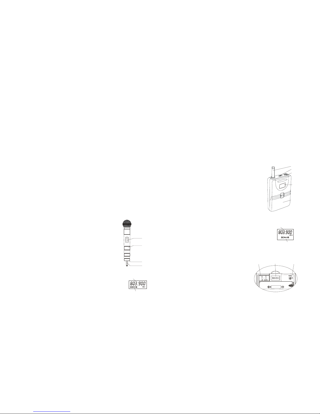
3.3Handholdmicrophone T14
3.3.1Installbatteries
Handholdmicrophone T14 wasshowninFig.6.Takeoutthe
microphone frompacking box,screwoff the batterycover,insert two
AAsizealkalinebatteriesinrightpolaritymarks,and screw closethe
batterycover.
3.3.2Turnon orturnoff themicrophone
Press the powerbutton (●)toturnon orturnoffthe microphone.
whenturnon the microphone,the operationfrequencyorchannel
numberand the powerlevelwilldisplaysonthe LCDscreen,see
Fig.7.Andturnoff the microphone,the LCDscreen willdisplay
“OFF and then go out.
3.3.3ChangeChannel
Press the UPbutton ( )andkeep foramoment,the “MHz inthe LCD
screen will flash, then releasethe UPbutton ( ),and press the UPbutton( )
orthe DOWNbutton ( )againtochange the operation frequency. Then press
the powerbutton (●)oncetofinishchange,then the “MHz willstop flashing.
3.3.4Changethedisplay content
TheLCD screen maydisplayoperationfrequencyorchannelnumber.Tochange the display
content,pressthe DOWNbutton ( )and keepforamoment,the “MHz inthe LCDscreen willflash,
then releasethe DOWNbutton ( ),and pressthe UPbutton( ),the contentwilldisplayalternately
between the frequencyand thechannelnumber.Press the powerbutton(●)tomakesureand quit,
and the “MHz inthe LCDscreen willstop flashing.
3.3.5Changethescreenlightmode
Therearetwolightmodesformicrophone T14 withscreen light: “ON and “OFF .Inthe “ON
mode,the screen lightkeep lighting whenthe microphone wasturned on;inthe “OFF mode,the
screen lightkeep lighting onlywhensomebutton be pressed down. Tochangethe screen lightmode,
press the DOWNbutton ( )and keepforamoment,the “MHz inthe LCDscreen will flash,then
releasethe DOWN button ( ),pressthe DOWNbutton ( )again, “LEdoN or “LEdoFF willbe shown,
press the UPbutton ( ),the displaycontentwill change between the “LEdoN and “LEdoFF .Press
~3~
the POWER button (●)tomakesureand quit,and the “MHz inthe LCD screen willstop flashing.
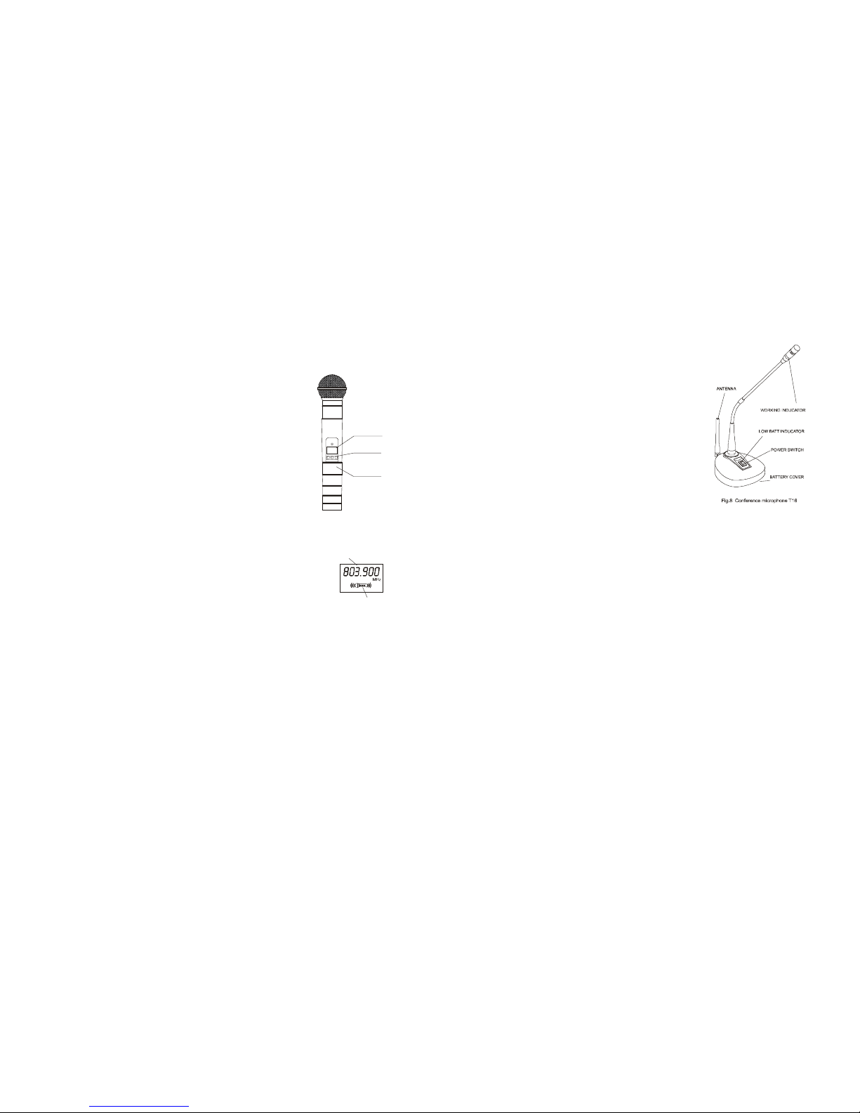
3.4 ConferenceMicrophone T16
3.4.1Installbatteries
MicrophoneT16 whichconsistofpedestaland gooseneck was
showninFig.8.Takeoutthe microphonefrompacking box,open the
batterycover,inserttwoAAsizealkalinebatteriesinrightpolarity
marks,and closethe batterycover.Takeoutthe gooseneck
microphone and RFantenna,and then mountthemontothe pedestal.
3.4.2Turnonorturnoffthemicrophone
Press the powerbutton toturnon the microphone,the red
low-batterylampflashonceand then off,whichmeanspoweris
enough towork,andthe workinglamplighton, meansthe microphone
isworking.
3.4.3Others
MicrophoneT16 is used forconferencesituations,toavoidthe cacophony,pleasecoverthe
windbreaksponge beforeusing the microphone;the bestpicking up distanceis 10~30cm.When
workingwithmodel8440 receiver,three setsof8440 receiversand twelvepiecesofthismicrophones
can working together,toavoidjamming,the frequencyofeachT16 microphone is fixed,sousersare
notabletochangethe frequency.Toavoidfeedback,weadviseyoutoshutthe othernon-using
microphonesand turnon itwhen speaking,turnoffitwhen speakover.
4Operations of receivers
4.1 True Diversity Receiver 8121
4.1.1Installand Place receiver
True diversityreceiver8121 wasshowninFig.9.Takeoutthe receiverand the receiveantennae
frompacking box;revolvethe twoantennae tothe twoANTsocketson the rearpanelofthe receiver.
Placethe receivernearthe performancearea (stage),Pointthe antennaeupward.Makesurethatthe
transmitter(microphone)willnevergetanyclosertothe receiverthan10 ft (3m);optimumseparation is
16 ft (5m).Thereshouldalwaysbe adirectline ofsightbetween the microphone andreceiver.Place
the receiverat least5ft(1.5m)awayfromanybigmetalobjects,walls,scaffolding,ceilings, etc.
4.1.2Switchonthepower
Takeoutthe poweradapter,checkifthe ACvoltagestated on the adaptermatchesthe AC
electronic socketinthe wall,and then putthe adapterintothe socket, connecting the poweroutput
~4~
LCD
SCREEN
BATTERY
COVER
BUTTONS
Fig.6Handholdmicrophone T14
Fig.8ScreenofT14
FREQUENCY
POWERLEVEL

cabletothe socketon therearpanelof the
receiver.
4.1.3Connectsignalcable
ConnectUNBALANCEDsocketin
receiverand MICINPUTinthe amplifier
withthe suppliedunbalancedaudiocable.
The BALANCEDsocketspecializesin
connectingsoundstage withtheoptional
balancedaudiocable.Donotusethe
Balanced and Unbalanced Sockets
simultaneously!Thismaycausesignal
loss orincreased noise.
4.1.4Adjustthevolumeinadvance
Adjustthe volumeofthe receiverand amplifierto “MIN and turnon the receiver,the LCDscreen
ofthe receiverwilllighton and displayasfig.10. Makesurethe frequencyorthe channelofthe receiver
arethe sametothe microphone.
Turnon the microphone,the
“MUTE willdisappear,and theRF
signalwillbe displayed.Atthe
sametime,the one ofthe diversity
indicator “Aor “Bwillbe
displayed,ifthe “Aappearmeansthe innerreceiverAgetsignal,whilethe Bworks ifthe “Bappear.
When youspeaktothe microphone,the AFsignalwillbe displayed.Moving the microphone,oneof the
“Aand “Bwillbe selected automatically toappearaccording tothebettersignal,thismeansthe
diversitycircuitis working toeliminating theblindarea.So,thiskind ofmodelis fitformorecomplicated
condition than common model.
4.1.5Setthevolume
Setthe VOLUMEtogetpropervolumewithoutfeedback.
4.1.6Changethefrequency
Tochange receivefrequency,press the UPkey( )orthe DOWNkey( ),then the frequencyand
the channelwillaugmentorabatesynchronously.
4.2True Diversity Receiver8122
4.2.1Installand Place receiver
True diversityreceiver8122 wasshowninFig.11. Takeoutthe receiverand thereceiveantennas
~5~
frompacking box;revolvethe twoantennaeto
the twoANTsocketsonthe rearpanelofthe
receiver.Placethe receivernearthe
performancearea (stage).Pointthe antennae
upward.Makesure,thatthe transmitter
(microphone)willnevergetanyclosertothe
receiverthan 10ft(3m),optimumseparation
is16 ft (5m). Thereshouldalwaysbe adirect
line ofsightbetween the microphone and
receiver.Placethereceiveratleast5ft(1.5m)
awayfromanybigmetalobjects,walls,
scaffolding,ceilings,etc.
4.2.2Switchonthepower
Takeoutthe poweradapter,checkifthe ACvoltagestated on the adaptermatchesthe AC
electronic socketinthe wall,andthen putthe adapterintothe socket,connectingthepoweroutput
cabletothe socketon therearpanelofthe receiver.
4.2.3Connectthesignalcable
ConnectUNBALANCEDsocketinreceiverand MICINPUTinthe amplifierwiththe supplied
unbalancedaudiocable.The BALANCEDsocketspecializesinconnecting soundstage with the
optionalbalancedaudiocable.DonotusetheBalanced andUnbalanced Socketssimultaneously! This
maycausesignalloss orincreased noise.
4.2.4Adjustthevolumeinadvance
Adjustthe volumeofthe receiverand amplifierto “MIN and turnon the receiver,the LCDscreen
ofthe receiverwilllighton and displayasfig.12.Makesurethe frequencyorthe channelofthe receiver
arethe sametothe microphones.
Turnon the microphone,the
“MUTE willdisappear,andthe
RFsignalwillbe displayed.Atthe
sametime,one ofthediversity
indicator “Aor “Bwillbe
displayed,ifthe “Aappearmeansthe innerreceiverAgetsignalwhiletheBworksifthe “Bappear.
When youspeaktothe microphone,the AFsignalwillbe displayed. Moving the microphone,the oneof
the “Aand “Bwillbe selected automaticallytoappearaccording tothe bettersignal,this meansthe
diversitycircuitisworking toeliminating the blind area.So,this kind ofmodelcan fitformore
complicated condition than common model.
~6~
Fig.10Screen ofreceiver8121
RFSIGNAL
AFSIGNAL
CHANNEL
MUTE
INDICATOR
DIVERSITY
INDICATOR
FREQUENCY
AB
Fig.12Screenofreceiver8122
RFSIGNAL
AFSIGNAL
CHANNEL
MUTE
INDICATOR
SCAN
INDICATOR
DIVERSITY
INDICATOR
FREQUENCY
AB
SCAN

4.2.5Setthevolume
Setthe VOLUMEtogetpropervolumewithoutfeedback.
4.2.6Changethefrequency
Ifyouneed tochangethe receiverfrequency,press the key “SET ,thenthe “MHz willflash,it
meansyoucan changethe frequencynow,tochange receivefrequency,pressthe UPkey( )orthe
DOWNkey( ),then the frequencyand the channelwillaugmentorabatesynchronously.
4.2.7LockedandUnlocked
Thebuttonsof true diversityreceiver8122couldbe locked. Tolockthe buttons, press theUPkey
()and keep for5seconds,the “LoCon willappearinthe LCD screen,and the buttonswillbe
disabled,afterthis,ifyou press thebuttons,the “LoC willappearonthe LCD screen,meansthe
buttonswaslocked.Tounlockthe buttons,pressthe UPkey( )and keepfor5seconds,the “LoC
oFF willappearon the LCDscreen,meansthe buttonswasunlocked.
4.2.8AutomaticallyScan
Receiver8122can scan thesignalfrequencyof themicrophone and storeitautomatically.Please
do asfollowing:firstmakesurethe microphone wasturned on,then pressthe DOWNkey( )until
“SCAN appearsinthe screen,releasethe key,press UPkey( )orDOWNkey( )toscan signal
upwardsordownwards.Whenitscan the signal,itwillstop scanning automaticallyand storage the
date.You can alsopress “SET keytostop scanning.Pleasepayattention:beforescanning,makesure
thereisonlyonemicrophoneon working,and thereis no interferentialsignalaroundit,otherwiseit will
stop scanning byerrorsignal.
4.2.9Adjustsquelch
Wecan adjustthe squelchgatetogetadifferentreceiverdistanceon Receiver8122,The wayis:
Press “SET keyanddon’treleaseituntilitappears SqL-90 ,Press UPkey( ),the dataon the
screen willenlarge to-85,-80etc.,itmeansthe squelchgateareincreased,accordingly,the receive
distanceshorten and the anti-jamming performanceimproving;PressDOWNkey( ),the dataon the
screen will diminishto-95 and etc.,itmeansthe squelchgatearedeclined,accordingly,thereceive
distancewillenlarge and theanti-jamming performancereduce.Afterthis,press “SET keytoconfirm
and exit.
4.3Receiver 8440
4.3.1Installand Place receiver
Receiver8440 wasshowninFig.13.
Therearefourreceiveunitsinthe receiver.
Takeoutthe receiverandthereceive
antennasfrompacking box,revolvethe four
~7~
antennae tothe fourANTsocketson the rearpanelofthe receiver,placethereceivernearthe
performancearea.Pointthe antennaeupward. Makesurethatthetransmitter(microphone)willnever
getanyclosertothe receiverthan 10 ft(3m),optimumseparation is16 ft (5m). Thereshouldalwaysbe
adirectline ofsightbetween the microphoneand receiver.Placethe receiverleast5ft(1.5m)away
fromanybigmetalobjects,walls,scaffolding,ceilings,etc.
4.3.2Switchonthepower
Checkifthe ACvoltage stated on the rearpanelofthereceivermatchesthe ACelectric socketin
the wallbeforeconnecting the powercableinReceiver.Otherwisemaycauseirreparabledamage to
the unit.
4.3.3Connectthesignalcable
ConnectMAXEDOUTPUTinreceiverand MIC INPUTinthe amplifierwiththe supplied
unbalancedaudiocable.Ifnecessary,you can useotheraudiocables,and connect4outputsockets
(MIC1~MIC4)toamplifierrespectively.
4.3.4Adjustvolume
Adjust the volumeof the receiverand amplifierto “MIN and turnon the receiver, the powersupply
indicatorwilllighton,and receivercan worknow.Turnon the microphone and speakwithit,the LED
levelmeterwilldenoting the magnitude ofthe sound.Then adjustthe volumeofthereceiverand the
amplifiertogetthe bestvolume.Pleasepayattention:don’tadjustthe volumetoo bigtoavoid
feedback,otherwiseitmaycauseirreparabledamage toyoursound box.
5Specifications
5.1 Specifications ofmicrophones
ModelT11T12 T14T16
Freq Range 730~950MHz
Freq number96 1
Freq stability ±10ppm
ModulationFM
RFoutput10~50mW
Audiobandwidth
40~18000Hz
T.H.D. at 1kHz ≤0.5%
Powersupply2×1.5V
Batteryleft15 hours
~8~

5.2Specificationsof receivers
Model8121 8122 8440
Freq Range 730~950MHz
Freq number96 4
Oscillation mode
PLLsynthesized
Freq stability ±10ppm
Receivemode Superheterodyne
Diversitytype True None
Inputsensitivity-90dBm-95~-60dBm-90dBm
Audiobandwidth
40~18000Hz
T.H.D.at1kHz ≤0.5%
S/N ratio ≥110dB
AudiooutputBalanced XLRand unbalanced 1/4 jacksocketMixed and Unmixed
Powersupply110V60Hzor220V50Hz
6 Hackneyed questions and solution
PhenomenonReasonSolution
Installbatterieswrongly on the
polarity Inspectthe polarityand install it
again
OutofpowerReplacethe batteries
ModelT16 indicator
notlighton when turn
onthe powerswitch BatteryinterfacerustClean orchange the interface
ModelT16 lowbattery
indicatorlight on LowinbatteryReplacethe batteries
Installbatterieswrongly on the
polarity Inspectthe polarityand install it
again
OutofpowerReplacethe batteries
ModelT11,T12,T14
haveno show on the
screen BatteryinterfacerustClean ofchange the batteries
The socketdo not electrifyCheckthe socketReceiverdidnot
electrify The fuseofreceiverattainted Checkorreplacethe fuse
Microphone do notturnon Turnon the correctmicrophone
The frequencynotmatchAdjustthe frequencyaccording to
the operationmanual
Receiverhaveno
reception
Overstep the operation distanceBacktocorrectoperation distance
The volumeistoo smallAdjustthe volumeofthe receiver
and amplifier
Receiverhave
reception butno
volume Audiocableconnectwrong or
badness Checkitand connectthe audio
cablecorrectly
Thereis cacophonyin
the sound box Thereis asameorsimilarsystem
nearit Change thefrequency,keepsome
distancefromreceiverto
computer,using mobiletelephone
Thereis screechfrom
sound box feedbackReducevolume,microphone
neverfacetothe sound box,and
keepsomedistancefrom
microphone tosound box
The sound
intermittence Outside the operation distanceBacktocorrectoperation distance
The operation distance
too short The condition is too complicated Avoidthe complicated condition,
suchasbigmetalobjects,walls,
scaffolding,etc
7Frequency List
7.1 Band 735 Frequency List
Group A Group B Group C
Channel
(Dec)
Channel
(Hex)
Freq.
(MHz) Channel
(Dec) Channel
(Hex)
Freq.
(MHz)
Channel
(Dec) Channel
(Hex)
Freq.
(MHz)
00A0 735.80
16 B0 740.60
32 C0 745.40
01A1 736.10
17 B1 740.90
33 C1 745.70
02A2 736.40
18 B2 741.20
34 C2 746.00
03A3 736.70
19 B3 741.50
35 C3 746.30
04A4 737.00
20 B4 741.80
36 C4 746.60
05A5 737.30
21 B5 742.10
37 C5 746.90
06A6 737.60
22 B6 742.40
38 C6 747.20
07A7 737.90
23 B7 742.70
39 C7 747.50
08A8 738.20
24 B8 743.00
40 C8 747.80
09A9 738.50
25 B9 743.30
41 C9 748.10
10AA 738.80
26 BA 743.60
42 CA 748.40
11AB 739.10
27 BB 743.90
43 CB 748.70
12AC 739.40
28 BC 744.20
44 CC 749.00
13AD 739.70
29 BD 744.50
45 CD 749.30
14AE 740.00
30 BE 744.80
46 CE 749.60
15AF 740.30
31 BF 745.10
47 CF 749.90
Group D
Channel
(Dec)
Channel
(Hex)
Freq.
(MHz)
48D0 750.20
49D1 750.50
50D2 750.80
51D3 751.10
52D4 751.40
53D5 751.70
54D6 752.00
55D7 752.30
56D8 752.60
57D9 752.90
58DA 753.20
59DB 753.50
60DC 753.80
61DD 754.10
62DE 754.40
63DF 754.70
~10~

7.2Band 793FrequencyList
Group A Group B Group C
Channel
(Dec)
Channel
(Hex)
Freq.
(MHz) Channel
(Dec) Channel
(Hex)
Freq.
(MHz) Channel
(Dec) Channel
(Hex)
Freq.
(MHz)
00 A0 793.10
16 B0 797.90
32 C0 802.70
01 A1 793.40
17 B1 798.20
33 C1 803.00
02 A2 793.70
18 B2 798.50
34 C2 803.30
03 A3 794.00
19 B3 798.80
35 C3 803.60
04 A4 794.30
20 B4 799.10
36 C4 803.90
05 A5 794.60
21 B5 799.40
37 C5 804.20
06 A6 794.90
22 B6 799.70
38 C6 804.50
07 A7 795.20
23 B7 800.00
39 C7 804.80
08 A8 795.50
24 B8 800.30
40 C8 805.10
09 A9 795.80
25 B9 800.60
41 C9 805.40
10 AA 796.10
26 BA 800.90
42 CA 805.70
11 AB 796.40
27 BB 801.20
43 CB 806.00
12 AC 796.70
28 BC 801.50
44 CC 806.30
13 AD 797.00
29 BD 801.80
45 CD 806.60
14 AE 797.30
30 BE 802.10
46 CE 806.90
15 AF 797.60
31 BF 802.40
47 CF 807.20
Group D Group E Group F
Channel
(Dec)
Channel
(Hex)
Freq.
(MHz) Channel
(Dec) Channel
(Hex)
Freq.
(MHz) Channel
(Dec) Channel
(Hex)
Freq.
(MHz)
48 D0 807.50
64 E0 812.30
80 F0 817.10
49 D1 807.80
65 E1 812.60
81 F1 817.40
50 D2 808.10
66 E2 812.90
82 F2 817.70
51 D3 808.40
67 E3 813.20
83 F3 818.00
52 D4 808.70
68 E4 813.50
84 F4 818.30
53 D5 809.00
69 E5 813.80
85 F5 818.60
54 D6 809.30
70 E6 814.10
86 F6 818.90
55 D7 809.60
71 E7 814.40
87 F7 819.20
56 D8 809.90
72 E8 814.70
88 F8 819.50
57 D9 810.20
73 E9 815.00
89 F9 819.80
58 DA 810.50
74 EA 815.30
90 FA 820.10
59 DB 810.80
75 EB 815.60
91 FB 820.40
60 DC 811.10
76 EC 815.90
92 FC 820.70
61 DD 811.40
77 ED 816.20
93 FD 821.00
62 DE 811.70
78 EE 816.50
94 FE 821.30
63 DF 812.00
79 EF 816.80
95 FF 821.60
Notice:ThefrequencyofMicrophoneT16andReceiver 8440isfixed.Thefrequencyfor each
MicrophoneT11, T12,T14and each Receiver 8122, 8440belongto acertain band. Donotuse the
microphoneand receiver with differentband.Youcan onlychange the frequency in thecurrent
band.
~11~
7.3 Band 803 Frequency List
Group A Group B Group C
Channel
(Dec)
Channel
(Hex)
Freq.
(MHz) Channel
(Dec) Channel
(Hex)
Freq.
(MHz)
Channel
(Dec) Channel
(Hex)
Freq.
(MHz)
00A0 803.90
16 B0 808.70
32 C0 813.50
01A1 804.20
17 B1 809.00
33 C1 813.80
02A2 804.50
18 B2 809.30
34 C2 814.10
03A3 804.80
19 B3 809.60
35 C3 814.40
04A4 805.10
20 B4 809.90
36 C4 814.70
05A5 805.40
21 B5 810.20
37 C5 815.00
06A6 805.70
22 B6 810.50
38 C6 815.30
07A7 806.00
23 B7 810.80
39 C7 815.60
08A8 806.30
24 B8 811.10
40 C8 815.90
09A9 806.60
25 B9 811.40
41 C9 816.20
10AA 806.90
26 BA 811.70
42 CA 816.50
11AB 807.20
27 BB 812.00
43 CB 816.80
12AC 807.50
28 BC 812.30
44 CC 817.10
13AD 807.80
29 BD 812.60
45 CD 817.40
14AE 808.10
30 BE 812.90
46 CE 817.70
15AF 808.40
31 BF 813.20
47 CF 818.00
Group D Group E Group F
Channel
(Dec)
Channel
(Hex)
Freq.
(MHz) Channel
(Dec) Channel
(Hex)
Freq.
(MHz)
Channel
(Dec) Channel
(Hex)
Freq.
(MHz)
48D0 818.30
64 E0 823.10
80 F0 827.90
49D1 818.60
65 E1 823.40
81 F1 828.20
50D2 818.90
66 E2 823.70
82 F2 828.50
51D3 819.20
67 E3 824.00
83 F3 828.80
52D4 819.50
68 E4 824.30
84 F4 829.10
53D5 819.80
69 E5 824.60
85 F5 829.40
54D6 820.10
70 E6 824.90
86 F6 829.70
55D7 820.40
71 E7 825.20
87 F7 830.00
56D8 820.70
72 E8 825.50
88 F8 830.30
57D9 821.00
73 E9 825.80
89 F9 830.60
58DA 821.30
74 EA 826.10
90 FA 830.90
59DB 821.60
75 EB 826.40
91 FB 831.20
60DC 821.90
76 EC 826.70
92 FC 831.50
61DD 822.20
77 ED 827.00
93 FD 831.80
62DE 822.50
78 EE 827.30
94 FE 832.10
63DF 822.80
79 EF 827.60
95 FF 832.40
Notice:Thefrequency ofMicrophoneT16and Receiver 8440isfixed.Thefrequencyforeach
MicrophoneT11, T12,T14and each Receiver 8122, 8440belongto acertain band. Donotuse the
microphoneand receiver with different band.Youcan onlychange the frequency in thecurrent
band.
~12~

7.4Band 840FrequencyList
Group A Group B Group C
Channel
(Dec)
Channel
(Hex)
Freq.
(MHz) Channel
(Dec) Channel
(Hex)
Freq.
(MHz) Channel
(Dec) Channel
(Hex)
Freq.
(MHz)
00 A0 840.10
16 B0 844.90
32 C0 849.70
01 A1 840.40
17 B1 845.20
33 C1 850.00
02 A2 840.70
18 B2 845.50
34 C2 850.30
03 A3 841.00
19 B3 845.80
35 C3 850.60
04 A4 841.30
20 B4 846.10
36 C4 850.90
05 A5 841.60
21 B5 846.40
37 C5 851.20
06 A6 841.90
22 B6 846.70
38 C6 851.50
07 A7 842.20
23 B7 847.00
39 C7 851.80
08 A8 842.50
24 B8 847.30
40 C8 852.10
09 A9 842.80
25 B9 847.60
41 C9 852.40
10 AA 843.10
26 BA 847.90
42 CA 852.70
11 AB 843.40
27 BB 848.20
43 CB 853.00
12 AC 843.70
28 BC 848.50
44 CC 853.30
13 AD 844.00
29 BD 848.80
45 CD 853.60
14 AE 844.30
30 BE 849.10
46 CE 853.90
15 AF 844.60
31 BF 849.40
47 CF 854.20
Group D Group E Group F
Channel
(Dec)
Channel
(Hex)
Freq.
(MHz) Channel
(Dec) Channel
(Hex)
Freq.
(MHz) Channel
(Dec) Channel
(Hex)
Freq.
(MHz)
48 D0 854.50
64 E0 859.30
80 F0 864.10
49 D1 854.80
65 E1 859.60
81 F1 864.40
50 D2 855.10
66 E2 859.90
82 F2 864.70
51 D3 855.40
67 E3 860.20
83 F3 865.00
52 D4 855.70
68 E4 860.50
84 F4 865.30
53 D5 856.00
69 E5 860.80
85 F5 865.60
54 D6 856.30
70 E6 861.10
86 F6 865.90
55 D7 856.60
71 E7 861.40
87 F7 866.20
56 D8 856.90
72 E8 861.70
88 F8 866.50
57 D9 857.20
73 E9 862.00
89 F9 866.80
58 DA 857.50
74 EA 862.30
90 FA 867.10
59 DB 857.80
75 EB 862.60
91 FB 867.40
60 DC 858.10
76 EC 862.90
92 FC 867.70
61 DD 858.40
77 ED 863.20
93 FD 868.00
62 DE 858.70
78 EE 863.50
94 FE 868.30
63 DF 859.00
79 EF 863.80
95 FF 868.60
Notice:ThefrequencyofMicrophoneT16andReceiver 8440isfixed.Thefrequencyforeach
MicrophoneT11, T12,T14and each Receiver 8122, 8440belongto acertain band. Donotuse the
microphoneand receiver with differentband.Youcan onlychange the frequency in thecurrent
band.
~13~
Informationin thismanualis subjectto change withoutnotice and doesnotrepresent
a commitmentonthe partof the vendor.We shall notbe liable foranyloss or damage
whatsoever arisingfromthe use of informationor any error contained in this manual.
Nopart ofthis manualmaybereproduced,storedin aretrieval systemortransmitted,
in any form orbyanymeans, electronic,electrical,mechanical,optical,chemical,
includingphotocopyingandrecording,foranypurpose withouttheexpress written
permissionof us.
Itisrecommended that allmaintenance andservice ontheproductshouldbe carried
out byusor ourauthorized agents.Wecannot acceptanyliabilitywhatsoever forany
loss or damagecausedby service, maintenanceorrepairby unauthorized personnel.
This manual suits for next models
6
Table of contents