Napoleon PVA81 User manual

1
:ROI6WHHO/WG1DSROHRQ5G%DUULH21/0*&DQDGD ID[ ZZZQDSROHRQILUHSODFHVFRP
This application occurs when venting through an exterior wall. Having
determined the correct height for the air terminal location, cut and
frame a hole in the exterior wall as illustrated to accommodate
the firestop assembly. Dry fit the firestop assembly before
proceeding to ensure the brackets on the rear surface fit to
the inside surface of the horizontal framing.
The length of the vent shield may be cut shorter for
combustible walls that are less than 8 1/2” thick but the
vent shield must extend the full depth of the combustible
wall.
A. Apply a bead of caulking (not supplied) around the corner
edge of the inside surface of the firestop assembly, fit the firestop assembly to
the hole and secure using the 4 screws W570-0026 (supplied in your manual
baggie).
B. Once the vent pipe is installed in its final position, apply high temperature
sealant W573-0007 (not supplied) between the pipe and the firestop.
DETERMINE
THE
CORRECT
HEIGHT
CAULKING
FIRESTOP
SPACER
VENT
SHIELD
FINISHING
MATERIAL
PVA81 POWER VENT ADAPTOR KIT
INSTALLATION INSTRUCTIONS
The HD81 uses 8” and 10” flexible venting. When installing the GPV for use
with the HD81, the 4”/7” reducer (W175-0310) is required. The reducer must
be properly secured and sealed to the appliance using high temperature
sealant W573-0007 Mill Pac (not supplied)before continuing with vent
installation. The 5’ section of stainless steel flex liner (supplied) must be
secured and sealed to the corresponding connector using a minimum of 3
screws and high temperature sealant W573-0007 Mill Pac (not supplied). Use
4” and 7” couplers to connect additional vent lengths up to 65 feet.
WARNING: The 5’ of stainless steel flex liner (supplied) must be installed
directly off the appliance.
INSTALLER: LEAVE THESE INSTRUCTIONS WITH THE APPLIANCE.
THESE INSTRUCTIONS ARE TO BE USED IN CONJUNCTION WITH THOSE FOR THE GPV AND HD81.
THIS INFORMATION SUPERSEDES THAT IN THE HD81 INSTALLATION INSTRUCTIONS.
CONSUMER: RETAIN THESE INSTRUCTIONS FOR FUTURE REFERENCE.
FIRESTOP VENTING INSTALLATION
TERMINAL INSTALLATION
REFER TO GPV INSTALLATION INSTRUCTIONS
14”
11 7/8”
Included in this kit:
W010-2362 Assembly, firestop spacer W410-0029 5’ - 4” stainless steel flex liner
W175-0001 4” coupler W500-0420 Plate, electrical box cover
W175-0013 7” coupler RP8 Restrictor, Kit
W175-0310 Connector, reducer 8/10” to 4/7” W500-0551 Plate, Dilution air
W410-0017 5’ - 7” flex liner W750-0218 Wire harness, unit
!
WARNING
THE FIRESTOP ASSEMBLY MUST BE INSTALLED WITH THE VENT SHIELD TO THE TOP.
DO NOT FILL THE CAVITY BETWEEN THE PIPE AND THE FRAMING WITH ANY TYPE OF MATERIAL.
TERMINALS MUST NOT BE RECESSED INTO A WALL OR SIDING MORE THAN THE DEPTH OF THE RETURN
FLANGE OF THE MOUNTING PLATE.

2
:ROI6WHHO/WG1DSROHRQ5G%DUULH21/0*&DQDGD ID[ ZZZQDSROHRQILUHSODFHVFRP
ADDING VENT LENGTH
If more vent pipe needs to be used to reach the
appliance, couple them together as illustrated. The
vent system must be supported approximately every
3 feet for both vertical and horizontal runs. Use
noncombustible strapping to maintain the minimum
clearance to combustibles.
NOTE: The final inner flex pipe that connects to the
4” and 7” reducer must be stainless steel.
HI-TEMP
SEALANT
#8 X 1/2” SELF DRILLING
SCREWS & WASHERS
INNER COUPLER
OUTER COUPLER
OUTER
FLEX PIPE INNER
FLEX PIPE
OUTER FLEX
PIPE
For safe and proper operation of the appliance, follow the venting
instructions exactly. All inner flex pipe and outer flex pipe joints may be
sealed using high temperature sealant W573-0002 (not supplied) or the
high temperature sealant W573-0007 Mill Pac (not supplied). However,
the high temperature sealant W573-0007 Mill Pac (not supplied) must be
used when connecting the reducer to the exhaust of the appliance and
when connecting the 4” stainless steel flex vent to both the reducer and the
coupler.
ELBOW
SPACERS
!
WARNING
DO NOT ALLOW THE INNER FLEX PIPE TO BUNCH UP ON THE HORIZONTAL OR VERTICAL RUNS AND
ELBOWS. KEEP IT PULLED TIGHT.
SPACERS ARE ATTACHED TO THE INNER FLEX PIPE AT PREDETERMINED INTERVALS TO MAINTAIN AS
EVEN AIR GAP TO THE OUTER FLEX PIPE. THIS GAP IS REQUIRED FOR SAFE OPERATION. A SPACER IS
REQUIRED AT THE START, MIDDLE AND END OF EACH ELBOW TO ENSURE THIS GAP IS MAINTAINED. THESE
SPACERS MUST NOT BE REMOVED.

3
:ROI6WHHO/WG1DSROHRQ5G%DUULH21/0*&DQDGD ID[ ZZZQDSROHRQILUHSODFHVFRP
Downward venting installations are only allowed when the
appliances is set to Intermittent Pilot Ignition (I.P.I.) Electronic
Ignition (E.I.). If an anti-condensation switch is being used,
downward vertical venting is not allowed.
It is recommended that the gas power vent be used with a gas appliance
that is equipped with Electronic Ignition. When installing the venting, these
parameters supersede the Vent Installation Section in the appliance's
Installation and Operating Instructions, as well as the following guidelines:
Maximum horizontal vent run with no rise is 65 feet total.
H = HORIZONTAL RUN V = VERTICAL RUN
Multi-elbow installations are possible up to a maximum of six 90°.
MAX
V1+V2+V3+
H1+H2+H3
MIN
V1+V2+V3+
H1+H2+H3
MAX
ELBOWS
65 FEET 10 FEET SIX 90°
MULTI ELBOW
MAX H+V MIN H+V MAX ELBOWS
65 FEET 10 FEET SIX 90°
VENT LENGTHS
MAX
H1+H2+V MIN
H1+H2+V MAX D MAX
ELBOWS
65 FEET 10 FEET 8 FEET SIX 90°
DOWNWARD VERTICAL VENTING

4VENTURI ADJUSTMENT
This appliance has an air shutter that has been factory set open according
to the chart below:
Regardless of venturi orientation, closing the air shutter will cause a more
yellow flame, but can lead to carboning. Opening the air shutter will cause a
more blue flame, but can cause flame lifting from the burner ports. The
flame may not appear yellow immediately; allow 15 to 30 minutes for the
final flame colour to be established.
AIR SHUTTER ADJUSTMENT MUST ONLY BE DONE BY A QUALIFIED
INSTALLER!
AIR
SHUTTER
OPENING
VENTURI
BURNER
ORIFICE
49.1
VENTURI ADJUSTMENT CHART
FUEL HD81
NG 3/16”
LP 7/16”
RESTRICTOR PLATE INSTALLATION
:ROI6WHHO/WG1DSROHRQ5G%DUULH21/0*&DQDGD ID[ ZZZQDSROHRQILUHSODFHVFRP
W415-0896 / B / 07.27.12
DILUTION AIR PLATE INSTALLATION
When vent lengths exceed 20’ in length it is recommended
that the larger dilution air plate (supplied) be installed to the
GPV terminal.
Remove the 2 screws on the underside of the GPV as
shown. Remove the dilution air plate and replace it with
the one supplied.
DILUTION AIR PLATE
77.4
Vertical installations may display a very active flame. If this appearance is not desirable, the vent exit may
be restricted using a restrictor vent kit (the appropriate kit has been supplied). This will reduce the velocity of
the exhaust gases, slowing down the flame pattern and creating a more traditional gentle flame appearance.
Specific instructions are included with the kit.

5
DÉTERMINEZ
LA BONNE
HAUTEUR
CALFEUTRAGE
ESPACEUR
COUPE-FEU
PROTECTEUR
DE CONDUIT
D’ÉVACUATION
MATÉRIAU
DE FINITION
:ROI6WHHO/WG1DSROHRQ5G%DUULH21/0*&DQDGDWpOpFRSLHXUZZZQDSROHRQIR\HUVFRP
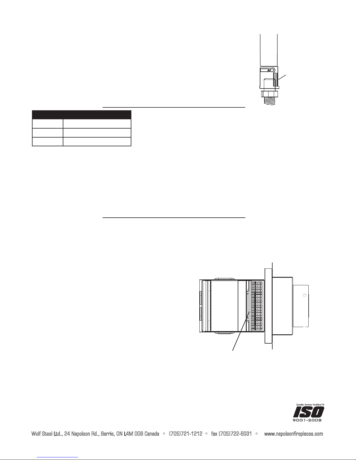
Cette configuration s’applique lorsque le conduit d’évent
traverse un mur extérieur. Une fois que vous aurez déterminé
la hauteur exacte pour l’emplacement de la terminaison,
découpez et charpentez une ouverture dans le mur extérieur tel
qu’illustré pour permettre l’installation de l’espaceur coupe-feu.
Avant de continuer, placez l’espaceur coupe-feu dans l’ouverture
pour vous assurer que les supports sur la surface arrière soient
placés à l’intérieure de la pièce de charpente horizontale.
Le protecteur de conduit d’évacuation peut être coupé plus court
pour les murs combustibles dont l’épaisseur est moins de 8 1/2” mais le
protecteur de conduit d’évacuation doit se prolonger sur toute la profondeur
du mur combustible.
A. Appliquez un joint de calfeutrage (non fourni) tout autour de la bordure de la face
intérieure de l’espaceur, installez l’espaceur dans le trou et fixez à l’aide des
quatre vis W570-0026 (fournies dans le sac de votre manuel).
B. Une fois que le conduit d’évent est en place, appliquez du scellant à haute température W573-0002 (non fourni)
entre le conduit d’évent et l’espaceur coupe-feu.
INSTRUCTIONS D’INSTALLATION DE LA
TERMINAISON MÉCANIQUE PVA81
Le HD81 utilise des conduits flexibles de 8” et de 10”. Quand le GPV est installé
pour être utilisé avec le HD81, vous devez utiliser le réducteur 4”/7” (W175-0310).
Le réducteur doit être fixé et scellé à l’appareil avec du scellant à haute température
Mill Pac W573-0007 (non fourni) avant de continuer l’installation de l’évacuation.
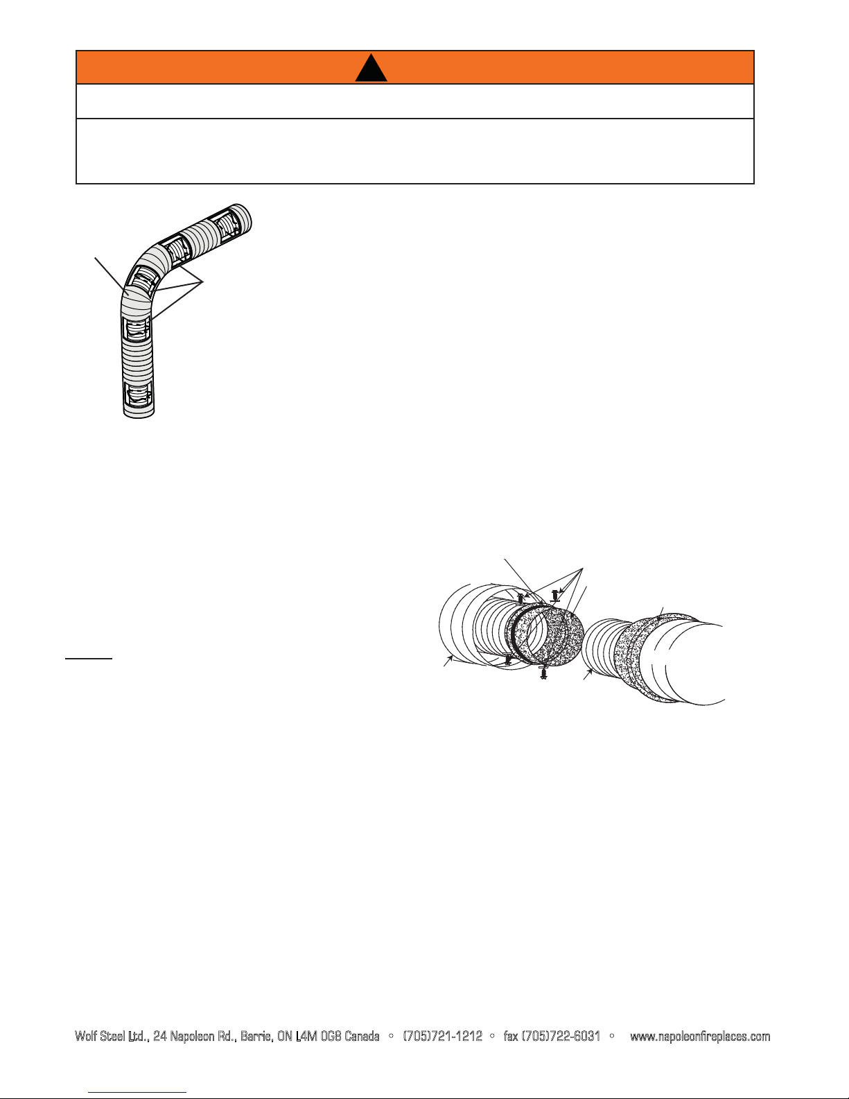
La section de 5’ de gaine flexible en acier inoxydable (fournie) doit être fixée et
scellée au connecteur correspondant à l’aide d’au moins trois vis et de scellant
à haute température Mill Pac W573-0007 (non fourni). Utilisez des bagues
d’accouplement de 4” et de 7” pour raccorder toute longueur additionnelle de
conduit d’évent jusqu’à un maximum de 65 pieds.
AVERTISSEMENT : La gaine flexible de 5’ en acier inoxydable (fournie)
doit être installée directement à partir de l’appareil.
INSTALLATEUR : LAISSEZ CE MANUEL AVEC L’APPAREIL.
CES INSTRUCTIONS DOIVENT ÊTRE UTILISÉES CONJOINTEMENT AVEC CELLES DU GPV ET DU HD81.
CES INFORMATIONS REMPLACENT LES INSTRUCTIONS D’INSTALLATION DU HD81.
PROPRIÉTAIRE : CONSERVEZ CE MANUEL POUR CONSULTATION ULTÉRIEURE.
INSTALLATION DE L’ÉVACUATION ET DE L’ESPACEUR COUPE-FEU
INSTALLATION DE LA TERMINAISON
RÉFÉREZ-VOUS AUX INSTRUCTIONS D’INSTALLATION DU GVP.
14”
11 7/8”
Included in this kit:
W010-2362 Assemblage de l’espaceur coupe-feu W410-0029 Gaine flexible de 4” en acier inoxydable - 5’
W175-0001 Bague d’accouplement de 4” W500-0420 Plaque, couvercle du boîtier électrique
W175-0013 Bague d’accouplement de 7” RP8 Plaque de restriction
W175-0310 Raccord, réducteur de 8/10” à 4/7” W500-0551 Plaque d’air de dilution
W410-0017 Gaine flexible de 7” - 5’ W750-0218 Harnais de fils
!
AVERTISSEMENT
L’ESPACEUR COUPE-FEU DOIT ÊTRE INSTALLÉ AVEC L’ÉCRAN PROTECTEUR ORIENTÉ VERS LE HAUT.
NE REMPLISSEZ L’ESPACE ENTRE LE CONDUIT D’ÉVENT ET LE MANCHON DE L’ESPACEUR COUPE-FEU
AVEC AUCUN TYPE DE MATÉRIAU.
LES TERMINAISONS NE DOIVENT PAS ÊTRE ENCHÂSSÉES DANS LE MUR OU LE REVÊTEMENT EXTÉRIEUR
PLUS QUE L’ÉPAISSEUR DE LA BRIDE DE LA PLAQUE DE MONTAGE.

6
:ROI6WHHO/WG1DSROHRQ5G%DUULH21/0*&DQDGDWpOpFRSLHXUZZZQDSROHRQIR\HUVFRP
AJOUT DE LONGUEUR D’ÉVENT
Si plus de sections de gaine doivent être utilisées
pour atteindre l’appareil, raccordez-les ensemble
tel qu’illustré. Les courses horizontales et verticales
du système d’évacuation doivent être supportées
à chaque 3 pieds approximativement. Utilisez
des supports incombustibles afin de maintenir le
dégagement minimal aux matériaux combustibles.
NOTE : La dernière section de gaine flexible
intérieure qui se raccorde au réducteur 4”/7” doit
être en acier inoxydable.
Afin d’assurer une opération sécuritaire et adéquate de l’appareil, vous
devez observer les instructions d’évacuation à la lettre. Tous les joints
des gaines flexibles intérieures et extérieures peuvent être scellés avec le
scellant à haute température Mill Pac W573-002 (non fourni) ou le scellant à
haute température Mill Pac W573-0007 (non fourni). Cependant, le scellant
à haute température Mill Pac W573-0007 (non fourni) doit être utilisé
lorsque vous raccordez le réducteur à l’évacuation de l’appareil et lorsque
vous raccordez la gaine flexible de 4” en acier inoxydable au réducteur et à
la bague d’accouplement.
ELBOW
SPACERS
!
AVERTISSEMENT
NE LAISSEZ PAS LA GAINE FLEXIBLE INTÉRIEURE SE TASSER CONTRE LES COURSES HORIZONTALES OU
VERTICALES ET LES COUDES. GARDEZ-LA TENDUE.
DES ESPACEURS SONT FIXÉS À LA GAINE FLEXIBLE INTÉRIEURE À INTERVALLES PRÉDÉTERMINÉS AFIN DE
GARDER UN ESPACE VIDE ÉGAL AVEC LA GAINE FLEXIBLE EXTÉRIEURE. CET ESPACE EST REQUIS POUR
QUE LE FONCTIONNEMENT SOIT SÉCURITAIRE. UN ESPACEUR EST REQUIS AU DÉBUT, AU MILIEU ET À LA
FIN DE CHAQUE COUDE AFIN DE MAINTENIR CET ESPACE VIDE. N’ENLEVEZ PAS CES ESPACEURS.
SCELLANT À
HAUTE
TEMPÉRATURE
VIS AUTO-PERCEUSES
#8 X 1/2” ET RONDELLES
BAGUE D’ACCOUPLEMENT
INTÉRIEURE
BAGUE
D’ACCOUPLEMENT
EXTÉRIEURE
GAINE FLEXIBLE
EXTÉRIEURE GAINE
FLEXIBLE INTÉRIEURE
GAINE FLEXIBLE
EXTÉRIEURE

7
:ROI6WHHO/WG1DSROHRQ5G%DUULH21/0*&DQDGDWpOpFRSLHXUZZZQDSROHRQIR\HUVFRP
Les installations d’évacuations descendantes sont seulement
permises quand l’appareil est réglé à Allumage intermittent de
la veilleuse (I.P.I.) Allumage électronique (E.I.). L’évacuation
verticale descendante n’est pas permise avec l’utilisation
d’un interrupteur anticondensation.
Il est conseillé d’utiliser la terminaison mécanique avec un appareil au gaz
muni d’un allumage électronique. Lors de l’installation de l’évacuation, les
paramètres suivants remplaceront la section « Installation des évents »
dans le manuel d’instructions d’installation et d’opération de l’appareil :
La déviation horizontale maximale sans élévation est de 65 pieds en tout.
H = COURSE HORIZONTALE V = COURSE VERTICALE
Les installations à coudes multiples sont possibles jusqu’à un
maximum de six coudes de 90°.
V1+V2+V3+
H1+H2+H3
MAXIMUM
V1+V2+V3+
H1+H2+H3
MINIMUM
COUDES
MAXIMUM
65 PIEDS 10 PIEDS SIX 90°
COUDES MULTIPLES
H+V MAXIMUM H+V MINIMUM COUDES MAXIMUM
65 PIEDS 10 PIEDS SIX 90°
LONGUEURS DES CONDUITS D’ÉVACUATION
H1+H2+V
MAXIMUM H1+H2+V
MINIMUM D
MAXIMUM COUDES
MAXIMUM
65 PIEDS 10 PIEDS 8 PIEDS SIX 90°
ÉVACUATION VERTICALE DESCENDANTE

8RÉGLAGE DU VENTURI
TABLEAU DU RÉGLAGE DU VENTURI
COMBUSTIBLE HD81
GN 3/16”
PL 7/16”
INSTALLATION DE LA PLAQUE DE RESTRICTION
:ROI6WHHO/WG1DSROHRQ5G%DUULH21/0*&DQDGD ID[ ZZZQDSROHRQILUHSODFHVFRP
W415-0896 / B / 07.27.12
INSTALLATION DE LA PLAQUE D’AIR DE DILUTION
Lorsque la longueur de l’évent dépasse 20’, il est conseillé
d’installer la plus grande plaque d’air de dilution (fournie)
sur la terminaison GPV.
Retirez les deux vis en dessous de la terminaison GPV.
Retirez la plaque d’air de dilution et remplacez-la par celle
fournie.
PLAQUE D’AIR DE DILUTION
L’ouverture du volet d’air a été préréglée en usine selon le tableau
ci-dessous :
Indépendamment de l’orientation du venturi, plus le volet est fermé,
plus la flamme est jaune et aura tendance à causer des dépôts de
carbone. Plus le volet est ouvert, plus la flamme est bleue et plus elle a
tendance à se détacher des orifices du brûleur. La flamme peut ne pas
être jaune immé-diatement; allouez de 15 à 30 minutes pour que la
couleur finale de la flamme se stabilise.
LE RÉGLAGE DU VOLET D’AIR DOIT ÊTRE EXÉCUTÉ PAR UN
TECHNICIEN OU INSTALLATEUR QUALIFIÉ!
VENTURI
INJECTEUR
49.1
OUVERTURE
DU VOLET
D’AIR
77.4
C
ertaines con
fi
gurations d’évacuation verticales peuvent avoir une
fl
amme très active.
S
i cette apparence
n’est pas désirée, la sortie du conduit d’évacuation doit être réduite en utilisant une plaque de restriction (la
trousse appropriée a été fournie). Ceci diminuera la vélocité des gaz de combustion, ralentissant ainsi le
mouvement de la flamme et créant une apparence plus traditionnelle. Les instructions sont incluses avec
l’ensemble.
Table of contents
Languages: