National Instruments nuDrive 4SX-411 User manual

FlexMotion™, National Instruments™, ni.com™, nuDrive™, and ValueMotion™are trademarks of National Instruments Corporation. Product and
company names mentioned herein are trademarks or trade names of their respective companies.
321942B-01 ©Copyright 1998, 2000 National Instruments Corp. All rights reserved. January 2000
USER GUIDE
NUDRIVE ACCESSORY
This user guide describes the electrical and mechanical aspects of the
nuDrive power amplifier accessory and describes how to use the nuDrive
with your motion controller.
Contents
Conventions ............................................................................................2
Introduction.............................................................................................2
What You Need to Get Started ...............................................................5
Safety Information ..................................................................................5
Installation and Connector Wiring..........................................................6
Front Panel Switches and Host Bus Interlock Circuit.............................6
Rear Panel Connector Wiring .................................................................7
Motor Power Terminal Blocks ........................................................7
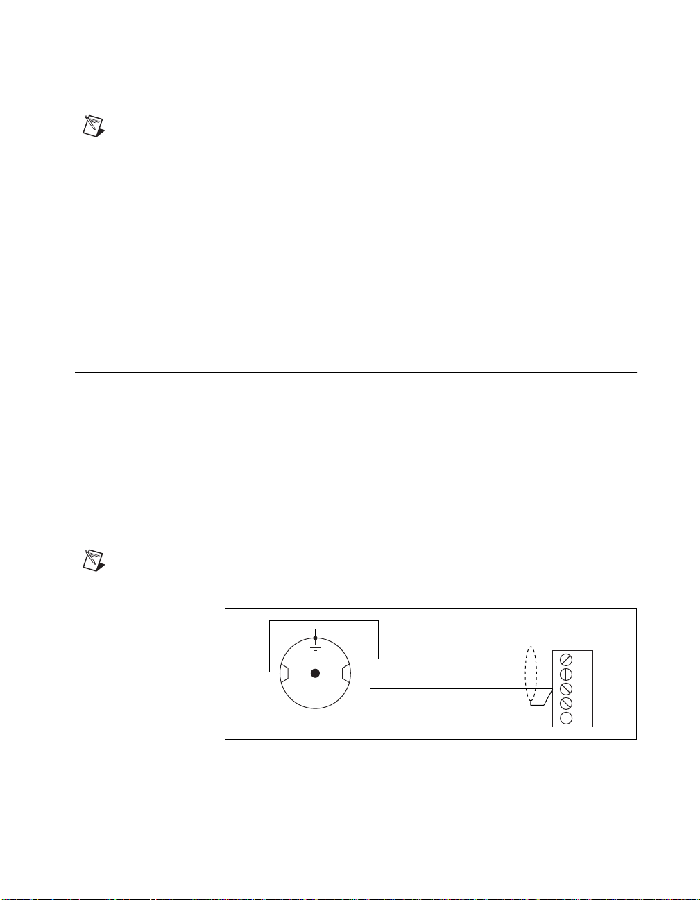
Encoder Terminal Blocks ................................................................8
Limit Switch Terminal Blocks.........................................................11
CX and SX nuDrive Configuration ..........................................11
CF nuDrive Configuration........................................................12
I/O Terminal Blocks ........................................................................13
CX and SX nuDrive Configuration ..........................................13
CF nuDrive Configuration........................................................15
Amplifier/Driver Command Signals.......................................................16
Servo Amplifier Signals...................................................................16
Stepper Driver Signals.....................................................................16
Optional Configurations..........................................................................16
E-Stop Terminal Block....................................................................16
Servo Amplifier Configurations ......................................................17
Adjusting Current Gain and Current Limits.............................19
Balancing the Amplifier Gain...................................................21
Status LEDs..............................................................................22
Stepper Driver Configurations.........................................................23
Stepper Motor Current..............................................................24
Microstep Selection..................................................................26
Stepper Motor Configurations ................................................................26
Specifications..........................................................................................29

nuDrive Accessory User Guide 2 www.ni.com
Conventions
The following conventions are used in this manual:
This icon denotes a note, which alerts you to important information.
This icon denotes a caution, which advises you of precautions to take to
avoid injury, data loss, or a system crash.
This icon denotes a warning, which advises you of precautions to take to
avoid being electrically shocked.
♦The ♦symbol indicates that the following text applies only to a specific
product.
overline Indicates the signal is active-low.
italic Italic text denotes emphasis, a cross reference, or an introduction to a key
concept. This font also denotes text that is a placeholder for a word or value
that you must supply.
CF nuDrive Refers to the 4CF-001 and 2CF-001 nuDrives.
CX nuDrive Refers to the 4CX-001 and 2CX-001 nuDrives.
SX nuDrive Refers to the 4SX-211, 2SX-211, 4SX-411, and 2SX-411 nuDrives.
stepper nuDrive Refers to the 4SX-211, 2SX-211, 4SX-411, and 2SX-411 nuDrives.
servo nuDrive Refers to the 4CF-001, 2CF-001, 4CX-001, and 2CX-001 nuDrives.
Introduction
Your nuDrive accessory is a complete power amplifier and system
interface for use with up to four axes of simultaneous or independent servo
or stepper motion control. Ideally suited to industrial and laboratory
applications, your nuDrive has everything you need to connect motors,
encoders, limit switches, I/O, and other motion hardware to National
Instruments motion controllers.

©National Instruments Corporation 3 nuDrive Accessory User Guide
Table 1 lists the available nuDrives and describes the properties of each
nuDrive.
The nuDrive can drive a broad range of servo or stepper motors.
Servo nuDrives use pulse-width modulation (PWM) amplifiers with a
user-specified peak output current rating and a DC bus voltage to drive
servo motors. Stepper nuDrives use a rugged microstepping bipolar
chopper driver. Stepper driver configurations are available in a wide range
of user-specified current per phase and voltage settings to drive stepper
motors. In all configurations, power supplies are built in and use standard
115 VAC for operation. Electronics are fan cooled to assure reliable
operation.
nuDrives simplify your field wiring through separate encoder, limit switch,
and motor power removable screw terminal connector blocks for each axis.
The terminal blocks do not require any special wiring tools for installation.
Refer to Table 2 for a summary of how to connect various motion
controllers to different nuDrives.
Table 1. nuDrive Properties
nuDrive Type
Number of Axes
Motor Type
Motion Board
Cable Connector
Driver/Amplifier
Nominal Bus Voltage
Driver/Amplifier
Type
AC Input
4SX-411 4Stepper
(2-phase) 50-pin 40 VDC Bus Microstepping Driver
IM483 115 V
(50/60 Hz)
2SX-411 2Stepper
(2-phase) 50-pin 40 VDC Bus Microstepping Driver
IM483 115 V
(50/60 Hz)
4SX-211 4Stepper
(2-phase) 50-pin 24 VDC Bus Microstepping Driver
IM483 115 V
(50/60 Hz)
2SX-211 2Stepper
(2-phase) 50-pin 24 VDC Bus Microstepping Driver
IM483 115 V
(50/60 Hz)
4CX-001 4DC Brush
Servo 50-pin 48 VDC Bus DC Brush Servo Amplifier
SSA 8/100 115 V
(50/60 Hz)
2CX-001 2DC Brush
Servo 50-pin 48 VDC Bus DC Brush Servo Amplifier
SSA 8/100 115 V
(50/60 Hz)
4CF-001 4DC Brush
Servo 100-pin 48 VDC Bus DC Brush Servo Amplifier
SSA 8/100 115 V
(50/60 Hz)
2CF-001 2DC Brush
Servo 100-pin 48 VDC Bus DC Brush Servo Amplifier S
SA 8/100 115 V
(50/60 Hz)

nuDrive Accessory User Guide 4 www.ni.com
nuDrives havethree levels ofamplifierinhibit/disableprotection for motion
systemshutdown.Thefrontpanelcontains both enableand powerswitches
for direct motor inhibiting and system power-down operations. Each
nuDrive also has a host bus power interlock that activates an amplifier
inhibit signal if the host computer is shut down or the motion controller
interface cable is disconnected. On nuDrives with the emergency stop
(E-Stop) option enabled, you can wire a 115 V emergency stop switch to
the rear panel I/O connector for remote interlock shut down, as described
in the E-Stop Terminal Block section of this document.
Each nuDrive is packaged in arugged aluminum enclosure that can be used
as a benchtop unit or that can be rack-mounted.
Table 2. nuDrive Connectivity
Controller Connection nuDrives
All 7344 controllers SH68-C68-S cable with a
68M-50F step/servo
bulkhead cable adapter
4SX-411
2SX-411
4SX-211
2SX-211
4CX-001
2CX-001
All FlexMotion-6C
controllers SH100-100-Fshieldedcable
cable 4CF-001
2CF-001
All 7324/7314
controllers* SH68-C68-S cable with a
68M-50F step/servo
bulkhead cable adapter
4SX-411
2SX-411
4SX-211
2SX-211
Non-73xx ValueMotion
stepper controllers SH50-50 shielded cable or
NB1 ribbon cable 4SX-411
2SX-411
4SX-211
2SX-211
All ValueMotion servo
controllers SH50-50 shielded cable or
NB1 ribbon cable 4CX-001
2CX-001
*For PXI-7324/7314 controllers prior to Rev. C, make the connection using a SH68-68-S
cable with a 68M-50F step/servo bulkhead cable adapter.

©National Instruments Corporation 5 nuDrive Accessory User Guide
What You Need to Get Started
To set up and use your nuDrive accessory, you will need the following
items:
❑The nuDrive accessory and nuDrive Accessory User Guide
❑Power cord (IEC type)
❑One or more of the following National Instruments cables and
adapters:
– SH68-68-S shielded cable, part number 185262-02
– NB1 ribbon cable, part number 180524-20
– SH50-50 shielded cable, part number 185319-02
– SH100-100-F shielded cable, part number 185095-02
– SH68-C68-S shielded cable, part number 186381-02
– 68M-50F step/servo bulkhead cable adapter, part number
185630-01
❑(Optional) ISO power supply (for FlexMotion-6C boards)
Detailed specifications for the nuDrive accessory are in the Specifications
section later in this guide.
Safety Information
Warnings Keepawayfromlivecircuits.Do notremoveequipment coversor shields unless
you are trained to do so. Hazardous voltages may exist even when the equipment is turned
off. To avoid a shock hazard, do not perform procedures involving cover or shield removal
unless you are qualified to do so and disconnect all field power prior to removing covers or
shields.
Do not operate damaged equipment. The safety protection features built into this device
can become impaired if the device becomes damaged in any way. If the device is damaged,
turn the device off and do not use until service-trained personnel can check its safety. If
necessary, return the device to National Instruments for serviceand repair to ensure that its
safety is not compromised.
Do not operate this equipment in a manner that contradicts the information specified in this
document. Misuse of this equipment could result in a shock hazard.
Do not substitute parts or modify equipment. Because of the danger of introducing
additional hazards, do not install unauthorized parts or modify the device. Return the

nuDrive Accessory User Guide 6 www.ni.com
device to National Instruments for service and repair to ensure that its safety features are
not compromised.
When connecting or disconnecting signal lines to the nuDrive terminal block screw
terminals, make sure the lines are powered off. Potential differences between the lines and
the nuDrive ground create a shock hazard while you connect the lines.
Connections, including power signals to ground and vice versa, that exceed any of the
maximum signal ratings on the nuDrive device can create a shock or fire hazard or can
damage any or all of the boards connected to the nuDrive chassis, the host computer, and
the nuDrive device. National Instruments is not liable for any damages or injuries resulting
from incorrect signal connections.
Installation and Connector Wiring
Caution Be sure to turn off the enable switches and the main AC power to your nuDrive
and host computer before connecting to your motion controller.
Connect the motion controller to the nuDrive interface cable. Wire the
motor power, limit switch, encoder, I/O, and E-Stop terminal blocks as per
the instructions and diagrams in this manual and/or your specific system
requirements. Finally, install the power cord into the rear panel AC
connector and plug it into a correctly rated power source.
Note For 50-pin ribbon cable interconnection, be certain that the colored indicator strip
(pin 1) on the cable between the motion controller and the 50-pin connector on the rear of
the nuDrive is properly aligned and inserted on both ends. 68- and 100-pin cables are keyed
metal-shell style.
Front Panel Switches and Host Bus Interlock Circuit
There are two lighted rocker switches on the nuDrive front panel, POWER
and ENABLE.
The POWER switch energizes the DC bus and the logic power supplies
(+5 V, +12 V), and illuminates to indicate that the main AC power is
present. If the POWER switch fails to illuminate, check the power cord and
main input fuse in the power connector.
The ENABLE switch enables or inhibits the servo amplifiers or stepper
drivers. It illuminates to indicate that it is switched on and that the logic
power supply +12 V output is functioning.

©National Instruments Corporation 7 nuDrive Accessory User Guide
Either switch can turn off the motors. However, as long as the nuDrive
POWER switch is still on, independent power and enable circuits cause the
incremental encoders to continue to track motor position while the
amplifiers (drivers) are disabled by the ENABLE switch being off.
Note The ENABLE switchilluminates wheneveritisswitchedon.It doesnotindicatethat
the amplifiers/drivers are disabled under the following conditions: E-Stop active (see
E-Stop Terminal Block), host bus interlock fault, or amplifier/driver protection fault (over
current, over temperature, and so on). Conversely, it does not light if the remote enable
function is used because the ENABLE switch is off (see I/O Terminal Blocks).
The nuDrive has a host bus interlock circuit that monitors the presence of
+5 V from the host computer and disables the nuDrive when the voltage
disappears or falls out of tolerance. This circuit shuts down the motors by
activating the Inhibit, or disable circuit for all axes, when the host computer
is disconnected from the nuDrive or inadvertently or unexpectedly shut
down.
Rear Panel Connector Wiring
Motor Power Terminal Blocks
For motor power wiring on the nuDrive, each axis has a separate 5-position
terminal block with removable screw terminals. There are two types of
wiring from the same connector for typical operation. Which of these two
configurations you use depends upon whether you are using the servo or
stepper version of the nuDrive. Figure 1 shows a typical servo motor
configuration pin assignment. Figure 2 shows a typical stepper motor
configuration pin assignment.
Note The dotted loop indicates a shielded cable.
Figure 1. Typical Servo Motor (DC Brush Type) Terminal Block Pin Assignment
1
2
3
4
5
Motor +
Motor –
Motor Case Ground
+–
Shield
Servo Motor

nuDrive Accessory User Guide 8www.ni.com
Figure 2. Typical Full-Coil Stepper Motor (2-Phase Type)
Terminal Block Pin Assignment
It is recommended you use shielded, 20 AWG wire or larger for the motor
power cable. If available, you should connect a case ground wire to pin 3
(Ground/Shield); this helps to avoid ground loops and signal noise
problems. (Case ground connects to the motor housing, and not to any of
the motor power terminals.)
The stepper nuDrives contain bipolar chopper drivers. The stepper motors
must be wired in a four-wire configuration as shown in Figure2. Unused
lead wires must be isolated and not connected. SeeStepper Motor
Configurations for additional information on connecting
6- and 8-wire motors and on the alternate half-coil configuration.
Caution Never connect unused center taps or winding terminals to pin 3.
Encoder Terminal Blocks
For quadrature incremental encoder signals, each nuDrive axis has a
separate 8-position terminal block with removable screw terminals.
Whereapplicable, the nuDrive accepts two types of encoder signal
inputs:single-ended (TTL) or differential line driver. You can
accommodate open-collector output encoders by using 2.2 kΩpullup
resistors to +5VDC.
Figure3 shows the typical encoder wiring pin assignment for single-ended
signal input. Figure4 shows the typical encoder wiring pin assignment for
differential line driver signal inputs.
1
2
3
4
5
Winding AStart
Winding B Start
Winding B End
Winding AEnd
Motor Case Ground
Shield
Stepper Motor

©National Instruments Corporation 9 nuDrive Accessory User Guide
Figure 3. Typical Single-Ended Encoder Wiring Pin Assignment
Figure 4. Typical Differential Line Driver Encoder Wiring Pin Assignment
If the encoder cable length is greater than 15 ft, you should use encoders
with line driver outputs for your applications. Power for a +5 V encoder is
available on pin 7, generated by a power supply inside the nuDrive.
Note If you require other encoder power values, reference an external power supply to the
Common (ground) signal on the 8-pin encoder terminal block.
nuDrives have differential inputs for Phase A, Phase B, and Index signals.
You can easily accommodate encoders with various phase relationships by
swapping the signals and/or connecting them to the inverting inputs as
specific applications require. The index pulse must occur when both
Phase A and Phase B signals are logic low, as shown in Figure 5. If the
Index pulse is inverted, try reversing the Index and Index signals on
differential encoders or wiring to the Index input with single-ended wiring.
1
2
3
4
5
6
7
8
Phase A
Phase B
Index
+5 V
Common
1
2
3
4
5
6
7
8
Phase A
Phase A
Phase B
Phase B
Index
Index
+5 V
Common

nuDrive Accessory User Guide 10 www.ni.com
Figure 5 shows the proper encoder phasing for CW (forward) motor
rotation.
Figure 5. Encoder Signal Phasing, CW Rotation
Servo and closed-loop stepper applications require consistent directional
polarity between the motor and encoder for stable operation. The National
Instruments motion control standard directional polarity is as follows:
• Positive = forward = clockwise (CW) facing motor shaft
• Negative = reverse = counter-clockwise (CCW) facing motor shaft
Figure 6 shows the clockwise and counter-clockwise motor rotation.
Figure 6. Clockwise and Counter-Clockwise Motor Rotation
When connecting the encoder wiring to your nuDrive accessory, you
should use shielded wire of at least 24 AWG. Both analog and digital noise
filters filter the encoder inputs in the nuDrive and on the motion controller
itself. You must use cables with twisted pairs and an overall shield for
improved noise immunity and enhanced encoder signal integrity. Figure 7
shows twisted pairs in a shielded cable.
Phase A
Phase B
Index
CCW CW

©National Instruments Corporation 11 nuDrive Accessory User Guide
Figure 7. Shielded Twisted Pairs
Note If you use an unshielded cable, noise can corrupt the encoder signals, resulting in
lost counts, reduced accuracy, and other erroneous encoder and controller operation.
Limit Switch Terminal Blocks
The limit and home switch connections for the nuDrive axes are configured
differently on different nuDrives, as described in the following sections.
CX and SX nuDrive Configuration
For end-of-travel limit and home switch connections, nuDrive axes have a
separate, six-position removable screw terminal connector block. All limit
signals are filtered in the nuDrive and debounced by the motion controller
toreducenoisesensitivity.Refer to Figures 8 and 9 for examples ofpassive
and active limit switch wiring using the terminal block pin assignments on
the CX and SX nuDrives.
Figure 8. Pin Assignment for the Passive Limit Switch Terminal Block on the
CX and SX nuDrives
Shield
+5 V
Common
Index
Index
B
B
A
Drain
A
1
2
3
4
5
6
CW Limit
Home Switch
+12 VDC
Common
CCW Limit
+5 VDC

nuDrive Accessory User Guide 12 www.ni.com
Figure 9. Pin Assignment for the Active Limit Switch Terminal Block on the
CX and SX nuDrives
CF nuDrive Configuration
On CF nuDrives, the per-axis High-Speed Capture input signal is available
on pin 4 of each limit switch terminal block. Pin 5 provides an External
Inhibit input signal for remotely inhibiting the nuDrive axis. All limit
signals are filtered in the nuDrive and debounced by the FlexMotion-6C
controllertoreducenoisesensitivity.TheCF nuDrives andFlexMotion-6C
controllersprovideforopticallyisolated limit switch inputs,andpin6is the
isolated (ISO) Common signal connection. Refer to Figure 10 for the CF
nuDrive terminal block pin assignments.
Figure 10. Pin Assignment for the Limit Switch Terminal Block on the
CF nuDrive
The Limit, High-Speed Capture, and External Inhibit signals are
opto-coupled inputs and require a voltage source. You can either use an
externalisolatedvoltagesource, oryoucan use the+5 Vand groundsignals
on the host computer by properly setting a jumper to connect the isolated
voltage (input) to 5 V and the ISO Common signal on the FlexMotion-6C
board. Refer to the FlexMotion-6C Hardware User Manual for more
information.Referto theI/OTerminalBlocks section of thisguideformore
information on the FlexMotion-6C isolated input connection.
1
2
3
4
5
6
CW Limit
Home Switch
Common
CCW Limit
+12
Out
GND
+12
Out
GND
+12
Out
GND
+12 VDC
+5 VDC
1
2
3
4
5
CW Limit
Home Switch
CCW Limit
High-Speed Capture
External Inhibit
ISO Common 6

©National Instruments Corporation 13 nuDrive Accessory User Guide
Caution The FlexMotion-6C board will be damaged if the isolated voltage selection
jumpers on the board are set to use the internal voltage source and an external source is
connected directly to these signals on the nuDrive. Be careful to review the configuration
of the isolated voltage jumper section prior to powering any FlexMotion-6C circuits or the
host PC containing the FlexMotion-6C board.
I/O Terminal Blocks
The I/O connectors are configured differently on different nuDrives,
as described in the following sections.
CX and SX nuDrive Configuration
For CX and SX nuDrives, general-purpose digital I/O lines are provided to
augment the motion signals. The I/O lines are organized into two separate
I/O connectors, with each group using a separate six-position terminal
block with removable screws. Figure 11 shows the two six-position I/O
terminal block pin assignments.
Figure 11. Pin Assignments for the Two Six-Position I/O Terminal Blocks on the
CX and SX nuDrives
The ENABLE switch, located on the front panel of your nuDrive, controls
the enable signal input. The active-low enable signal input is also available
on pin 5 of each I/O terminal block and can remotely enable all axes in the
nuDrive. You can use either enable input on the I/O terminal blocks OR the
front panel ENABLE switch to enable the nuDrive accessory. E-stop inputs
and the host bus interlock also affect the ENABLE function.
Note The front panel ENABLE switch is wired in parallel to the active-low enable signal of
the I/O connector. To use the enable signal in the I/O connector(s), the front panel ENABLE
switch must be off (not illuminated).
1
2
3
4
5
6
I/O 1
I/O 2
I/O 4
Common
I/O 3
Enable
1
2
3
4
5
6
I/O 5
I/O 6
I/O 8
Common
I/O 7
Enable
ENABLE Switch
(ON = Closed)

nuDrive Accessory User Guide 14 www.ni.com
The ENABLE switch is illuminated whenever it is switched on. It will not indicate that the
amplifiers/drivers are disabled under the following conditions: E-Stop (see the E-Stop
Terminal Block section), Host Bus interlock fault, or amplifier/driver protection fault.
Conversely, it will not light if the external Enable function is used via the I/O terminal blocks.
♦SX nuDrives
When using an SX nuDrive, I/O pins 5 through 8 reflect the status of the
driver inhibits for axes 1 through 4 respectively. Each driver inhibit status
signal is the combination of the E-stop, enable, host bus interlock, and per
axis inhibit signals.
♦CX nuDrives
Tousetheamplifier inhibit functionality of the7344controller, set jumpers
JP2 through JP5 to the Inhibit position (recommended). When the jumpers
are set to the Inhibit position, I/O lines 5 through 8 reflect the status of the
driver inhibits for axes 1 through 4 respectively. To use I/O lines
5 through 8 as general purpose digital I/O signals (required for
ValueMotion servo controllers), set jumpers JP2 through JP5 to the
Digital I/O position.
Note Your CX nuDrive is shipped with jumpers JP2 through JP5 in the Digital I/O
position. These jumpers are located near the left edge of the interface board inside the
nuDrive, as shown in Figure 12.
Figure 12. Jumper Locations
Figure 13. CX nuDrive Jumper Configuration
1JP2 2. JP3 3JP4 4. JP5
1
2
3
4
Digital I/O Inhibit

©National Instruments Corporation 15 nuDrive Accessory User Guide
CF nuDrive Configuration
There are two I/O connectors (upper and lower) on the CF nuDrive. Each
I/O connector uses a six-position removable screw terminal block. The
upper terminal block provides access to four channels of ±10 V A/D
converter analog input as well as analog reference voltage output from the
converter circuit and reference common signal connections. The lower
terminal block provides access to breakpoint output digital I/O signals as
well as an isolated external power supply voltage input connection. Refer
to Figures 14 and 15 for the upper and lower FlexMotion-compatible I/O
terminal block pin assignments.
Figure 14. Upper I/O Terminal Block Pin Assignment on the CF nuDrive
Figure 15. Lower I/O Terminal Block Pin Assignment on the CF nuDrive
The breakpoint output digital signals are opto-coupled outputs and require
an isolated voltage source connected to the isolated voltage and isolated
common inputs. You can either use an external isolated voltage source, or
you can use the +5 V and ground signals on the host computer by properly
setting a jumper to connect the isolated voltage (input) to 5 V and the ISO
Common signal on the FlexMotion-6C board. Refer to the FlexMotion-6C
Hardware User Manual for more information.
1
2
3
4
5
6
A/D Input Channel 1
A/D Input Channel 2
A/D Input Channel 4
Analog Common
A/D Input Channel 3
Analog Ref. Output
1
2
3
4
5
6
Breakpoint Output 1
Breakpoint Output 2
Breakpoint Output 4
Isolated Common
Breakpoint Output 3
Isolated Voltage (Input)

nuDrive Accessory User Guide 16 www.ni.com
Amplifier/Driver Command Signals
Servo Amplifier Signals
The servo amplifiers used in the servo versions of the nuDrive accept an
industry-standard ±10 V analog torque (current) command signal. Servo
motion controllers used with the nuDrive provide this standard output and
are programmed to close both the velocity loop and position loop using an
enhanced PID algorithm.
Stepper Driver Signals
For stepper drivers, there are two industry standards for command signals:
• Step and Direction signals (nuDrive standard)
• Independent CW and CCW pulses
The nuDrive uses stepper drivers that have active-low step and direction
inputs. You must configure the stepper outputs of your stepper controller
for Step and Direction signals with inverted (active-low) polarity. This
configuration is the National Instruments default output configuration for
stepper controller boards and nuDrives.
Optional Configurations
Warning Be sure to turn off the ENABLE switch and disconnect the main AC power as
well as the E-Stop 115 VAC input from the nuDrive before opening the nuDrive cover or
accessing any components within the nuDrive.
This section describes optional configurations for your nuDrive accessory.
The nuDrive is factory configured with default settings appropriate for
many applications. If required, you can modify the parameters and settings
on the individual axis drivers to meet your specific application
requirements.
E-Stop Terminal Block
The E-Stop option has a separate three-position removable screw terminal
block on the nuDrive back panel.
Note Your nuDrive is shipped with the E-Stop disabled. To enable the E-Stop, remove the
jumperfromJP1 located ontheinterface boardinsidethenuDrive.JP1is the single two-pin
header near the E-Stop 3 position terminal block.

©National Instruments Corporation 17 nuDrive Accessory User Guide
Figure16 shows the location of the E-Stop terminal block (and E-Stop
configuration jumper) on the interface board.
Figure 16. E-Stop Location
If you enable the E-Stop option, you must apply a 115 VAC signal to pins
1 and 3 in addition to the normal nuDrive enable (ENABLE switch or I/O
connector enable input, if applicable) for the nuDrive’s amplifiers/drivers
to be enabled (not inhibited). If you disconnect the 115 VAC with the
E-Stop option selected, the amplifiers/drivers are immediately disabled
(inhibited) regardless of the status of the ENABLE switch or enable input.
Refer to Figure17 for more information on the E-Stop terminal block pin
assignment.
Figure 17. E-Stop Terminal Block Pin Assignment
Note The front panel ENABLE switch will remain illuminated even when the 115 VAC
signal is removed from the E-Stop connector, disabling the axes.
Servo Amplifier Configurations
The servo nuDrive uses high-efficiency PWM amplifiers configured as
torque blocks (current amplifiers or transconductance amplifiers). The
current gain is given in amps/volt and defines the relationship of the input
command voltage to the current output. The peak current limit is the
maximum current that your motor can withstand for short periods of time.
The continuous current limit is the maximum current that your motor can
withstand indefinitely.
1E-Stop 2JP1
1
2
1
2
3
115 VAC (Line)
115 VAC (Neutral)
NC

nuDrive Accessory User Guide 18 www.ni.com
Figure 18 shows the command voltage input to current output relationship
for periods of time less than approximately two seconds. The maximum
current output corresponds to the peak current limit, Ipeak.
Figure 18. Input Voltage to Output Current Relationship for Periods of Time
Less Than Two Seconds
Figure 19 shows the command voltage input to current output relationship
for periods of time greater than approximately two seconds. The maximum
current output corresponds to the continuous current limit, Icont, so
command voltages that would result in a higher current output than Icont
when the gain is applied instead result in a current output of Icont.
Figure 19. Input Voltage to Output Current Relationship for Periods of Time
Greater Than Two Seconds
0 A
Input Command Voltage
0 V
+Ipeak
+Icont
–Ipeak
–Icont
Output Current
Gain Applied
+Vmax
–Vmax
0 A
Input Command Voltage
0 V
+Ipeak
+Icont
–Ipeak
–Icont
Output Current
Gain Applied
+Vmax
–Vmax

©National Instruments Corporation 19 nuDrive Accessory User Guide
The amplifier peak and continuous current limits and the current gain have
been factory set for 5 A continuous and 10 A peak current output. Verify
that these settings are appropriate for your application before powering
your motors.
Adjusting Current Gain and Current Limits
You can adjust the current gain and current limits by changing the values
of R6, R7, R40, and R42 on the servo amplifiers. The resistors are standard
1/4 W axial leaded type and are plugged into sockets on the PWM per axis
servo drives.
Note Some components on your nuDrive are missing from their sockets. These
components were removed at the factory to configure the amplifier as a torque (current)
block.
Configure the current gain on the nuDrive so that the value of the maximum
command voltage, when multiplied by the gain, results in the value of the
maximum allowable peak current, as shown in Figure 18.
Calculate the gain using the following formula:
where Gain represents the gain value in amps/volt, Ipeak represents the
maximum allowable peak current, and Vmax represents the maximum
command voltage from your motion controller.
Note ±10 V is the maximum/minimum command voltage for National Instruments
motion controllers.
Once you have calculated your gain value, determine the resistor values for
R6 and R7 using the following formula:
where R6,7 is the value for both resistor R6 and resistor R7 in kΩ.
After setting the gain value, you need to adjust the values of the R40 and
R42 resistors to configure your peak current limit and continuous current
limits.
Gain Ipeak
Vmax
-----------=
R67
,50
Gain
-------------=

nuDrive Accessory User Guide 20 www.ni.com
Use the following formula to calculate the value for R42, which determines
the peak current limit:
where R42 represents the resistor value in kΩand Ipeak represents the
maximum allowable peak current for the motor.
Use the following formula to calculate the value for R40, which determines
the continuous current limit:
where R40 represents the resistor value in kΩand Icont represents the
maximum allowable continuos current for the motor.
Table 3 liststhefactorydefault valuesfor the current gain andcurrentlimits
resistors.
Note The 47.5 kΩvalue for R6 and R7 actually corresponds to a maximum output current
of 10.5 A rather than 10 A (although the actual output current will never exceed the 10 A
configured by R42). This is because 47.5 kΩis the closest standard resistor value below
the 50 kΩvalue that would correspond to a gain of 1.0 and, therefore, a maximum output
current of 10 A. Use the closest resistor value below the value you calculate for R40 and
R42 to ensure that your current limits do not exceed your motor’s specifications. Use the
closest resistor value below the value you calculate for R6 and R7 to ensure that your gain
value provides a maximum current output that matches or exceeds your peak current
setting (the drive will not actually output current that exceeds the peak current setting).
As an example, if you used a maximum input command voltage value of
±10 V, and you wanted to set your peak current limit to 6.4 A and your
continuous current limit to 2.7 A, you would calculate your resistor values
as demonstrated in the following example.
Table 3. Default Current Gain and Current Limit Resistor Values
Resistor Value Description
R6 47.5 kΩCurrent gain of 1.1 A/V
R7 47.5 kΩCurrent gain of 1.1 A/V
R40 3.3 kΩContinuous current limit of 5 A
R42 10 kΩPeak current limit of 10 A
R42 10 Ipeak
×
20 Ipeak
–
-----------------------=
R40 2Icont
×
8Icont
–
-------------------=
This manual suits for next models
7
Table of contents
Other National Instruments Amplifier manuals

National Instruments
National Instruments PXI-5691 User manual

National Instruments
National Instruments NI PXI-5690 User manual

National Instruments
National Instruments PXIe-4610 User manual

National Instruments
National Instruments PXI-5695 User manual

National Instruments
National Instruments PXIe-4610 Manual

National Instruments
National Instruments VXI-SC-1102 User manual