National Mower IM25 User manual

NATIONAL MOWER CO. 700 Raymond Ave., P.O. Box 14299, St. Paul, Minnesota 55114-0299, U.S.A.
Phone (651) 646-4079 Fax (651) 646-2887
www.nationalmower.com
JANUARY 2000
IM25
INFIELD MOWER
OWNERS MANUAL

NATIONAL IM25 Infield Mower
®
3
Specifications
Engine: 3.5 hp Briggs & Stratton I/C 4 cycle
w/gear reduction of 6:1
Width of cut: 25
Height of cut: 1/2 to 2
Weight: 270 lbs. without fuel
Dimensions: 65" length w/basket x 32" width x
39-1/2"height
Gas tank : 4 quart capacity
Fuel: Unleadedregulargasoline
Safety Precautions
·Allow only responsible persons that are familiar
with the controls to operate this equipment.
·Always operate with all guards and front-throw
basket in place.
·Never attempt to remove or replace the basket
when reel is engaged.
·Inspect rollers, reel and drive for debris or foreign
object and remove before starting to mow.
·Followengine manufacturersrecommendations
for proper gas, oil and maintenance procedures.
·Be alert when mowing for objects in the mowing
path.
·Never attempt to adjust cables or cutting height
when engine is running.
·Useprotective eyewear whenmowing.
·Use extreme caution when handling gasoline, it
is highly flammable.
Introduction
This machine has been designed with professional
quality components to specifically mow baseball infield
turf. Other uses include golf courses and turf
contractors. National welcomes your comments.
Additional information will gladly be furnished by
calling, writing or e-mailing the company. Please furnish
us with the model number, serial number and date of
purchase when contacting us about your machine.
Designations of right, left, front and rear are used
in the position of the operator when mowing.
Assembly Instructions
Carefully inspect your machine and crate for damage
that could have occurred during shipment. If damages or
shortages are noted, have the transportation company
representative indicate this on the bill of lading. Claims
for shipping damages must be noted by the consignee
at the point of designation and filed with the
transportationcompany.
1. Carefully uncrate the machine.
2. Attach the lower Handle Bar Assembly (1, Fig. B)
to the Handle Bar Brackets (2, Fig. A) with pivot
pins, flat washers and cotter pins from the loose
parts bag.
3. Insert Handle Adjustment Rods (3 , Fig. A) into
Lower Handle Bar Assembly and Adjustment
Brackets (4, Fig. A) on countershaft assembly and
secure with flat washers and cotter pins from the
loose parts bag. Use the front holes in the
adjustment brackets for the highest handle position
and the rear holes for the lowest position.
4. Pivot Upper Handle Bar Assembly (5, Fig. A & B) to
align with holes in the lower handle bar assembly
and fasten with four 5/16"24 x 1-1/2" cap screws
and hex nuts.
5. Hook Brake Rod Spring (6, Fig. B) to attaching tab
on the mower top plate.
6. Set attachment pins of Grass Basket (7, Fig. A) in
grooves of Basket Brackets (8, Fig. A).
Initial Starting Procedure
1. Engine crankcase oil has been installed at the
factory. However, it is recommended that the
engine be inspected for presence of oil at the proper
level (see engine manual) before starting.
2. Fill engine gas tank with unleaded regular gasoline.
3. Engage Parking Brake (9, Fig. A) by pulling lever
backand over center to lock.
Starting Instructions
1. Turn the red Fuel Valve (10, Fig. A), located on the
right side of the engine, 1/4 turn clockwise to
switch fuel supply to "On".
2. Press Ignition Switch (11, Fig. B), located on the
front of the engine to the "On" position.
3. Slide Choke (12, Fig. A) which is the white lever at
the back of the engine, to the right or "On" position.
4. Set Throttle Control (13, Fig. A) half way between
fast (full forward) and slow (full back).
5. Pull Rope Start Handle (14, Fig. A) sharply and
start engine.
Do not pull back Drive Bail Handle (15, Fig.
A) or move Clutch Handle (16, Fig. A)
forwardwhen startingengine.
6. Move choke lever left to the "Off" position as soon
as the engine starts.

IM25OM-1/2000-250
4
Operating Instructions
1. Unlock Parking Brake (9, Fig. A) by moving lever
forward.
2. Pull Drive Bail (15, Fig. A) slowly back to handle to
move forward. CAUTION: Make sure your path is
clearbefore movingforward.
3. Adjust Throttle Control to desired mowing speed.
4. Engage Reel Drive Lever (16, Fig. A and B) to start
mowing.
5. Release drive bail slightly from handle to disengage
reel.
6. Release drive bail completely to stop the mower
forwardmovement.
7. To shut off mower, pull throttle control all the way
back to slow, push ignition switch to off and
engageparking brake.
Maintenance
GENERAL
1. Empty basket of clippings periodically to prevent
spilling.
2. After each mowing session, clean clippings out of
basket, off reel and all other surfaces to prevent
corrosion.
3. Inspect reel and bearing surfaces for foreign material
that might prevent reel from rotating freely and clean
as necessary.
4. Followengine manufacturersrecommendations
carefully to prolong engine life.
LUBRICATION
There are Zerk Grease fittings (17, Fig. B) on each
end of the reel and on each Roller Adjuster (18, Fig. C).
Use a lithium base type grease at these locations every 8
hours of operation. Use a light machine oil at all pivot
points every 30 hours of operation.
Adjustments
CONTROLS
Adjustment of control cables have been made at
the factory before shipment. If additional adjustment is
needed, move adjusting nuts at the machine end of the
cables.
HEIGHTOF CUT
Cutting height should be preset by the dealer
according to ordering instructions prior to delivery. If a
change in cutting height is required, the following proce-
dure must be followed:
1. There are two positions available for the Rear Roller
Assembly (19, Fig. A). The bearings for the rear
roller shaft must be located in the lower position if
the cutting height is over 1 and the upper position if
the cutting height is 1 or less. Disassembly of the
rear roller assembly is necessary to change the
bearing location. See Figure 4 for reference.
Reel blades are sharp! Never attempt to
adjust cutting height of reel to bed knife
while the engine is running.
2. Adjust cutting height by loosening the top and
bottom Adjusting Nuts (20, Fig. C) which hold roller
adjusters for the Front Roller (21, Fig. B). It is
important to get roller adjusted the same height on
each end so that there will be uniform cutting the
entire width of the mower. Do not adjust by sight.
3. After loosening adjusting nuts on each side, place a
board or gauge plate of the desired height under bed
knife back bar and then tighten nuts.
REELTO BED KNIFE
The Reel Adjustment Bolt (22, Fig. C) regulates the
distance from the bed knife. To reduce the distance, turn
the locking hex nut on each side of the reel up. Proceed
slowly and do not over adjust. Turn about 1/8 of a turn to
start with. Do not get the reel so tight that it is hard to
turn by hand. A too tight reel will cause excessive wear.
The reel should wipe or lightly touch the bed knife.
Check to see that the blades are cutting the paper all
the way across. Tighten lock nuts.
Useheavy gloves andbe carefulblades
aresharp.
REELENDPLAYADJUSTMENT
As the reel is used, normal wear of the reel bearings
will cause end play. This condition could cause uneven
wear to moving parts and uneven cutting of turf.
Test for end play periodically by trying to move the
reel from side to side in the frame. If there is any move-
ment, adjust by loosening the lock nut (23, Fig. B) on the
adjustment bolt, located inside the right end of the reel.
Turn adjustment bolt in one half turn or less. Do not over
tighten as this will cause excessive bearing wear. Test
again for end play. If reel is rotating freely and no end
play can be detected, retighten the lock nut on the
adjusting bolt.

NATIONAL IM25 Infield Mower
®
5
FIGURE A
FIGURE B
FIGURE C

IM25OM-1/2000-250
6
FIGURE D
FIGURE E
Backlappinggears are
shown disengaged.
The gears must be in
this position when
mowing.
Raise mower up until drive roller
clears the ground.
Backlapping gears are shown
engaged.The gearsmust bein
thispositionwhenbacklapping.
Backlapping
Backlapping is a very important step in maintaining
sharp reel blades on the mower. This procedure should
be performed when the reel blades and bed knife become
slightly rounded and the turf is not cut cleanly after a
slight bed knife adjustment. Also, after grinding the bed
knife and reel, backlapping should be done to establish a
perfect match between the be knife and the reel blades.
The reel must run in a reverse direction to be backlapped.
1. Make sure to adjust the reel to the bed knife so that
the reel is level with the bed knife and light contact
is maintained.
2. Remove the Right Side Guard (24, Fig. A).
3. Raise the mower up off the ground until the rear
roller clears the ground as shown in Figure D.
4. Loosen Hex Nut (25, Fig. C) on the back lap
assembly, pivot assembly rearward and tighten hex
nut as shown in Figure D.
5. Start engine and run at half throttle. Engage drive
clutch.
6. With reel running, apply lapping compound to the
reel with a 2 or 3 brush. Apply compound evenly to
themoving blades.
Be extremely careful not to let the brush, your
fingers or your clothing get caught in the reel.
Use approved safety glasses and gloves to
protect you from flying particles and abrasives.
Many types of compounds are available for lapping.
We recommend a good pre-mixed water soluble com-
pound. Pre-mixed compound saves time required to mix,
eliminates abrasive waste, rinses off with water and is
available In all grit ranges from course to fine.
7. Stop the reel and examine both the bed knife and
reel blades to see that the cutting edges uniformly
sharp. If not, gradually tighten reel adjuster bolts
(see Reel To Bed Knife Adjustment) and then
repeat Step 6 above until achieving the proper
sharpness.
8. Rinse off the compound thoroughly with water to
removeallabrasive.
9. Loosen the hex nut on the backlap assembly and
pivot assembly forward to disengage rear roller.
Tighten nut in the position shown in Figure E.
10. Lower machine to the ground and replace right side
guard.

NATIONAL IM25 Infield Mower
®
7
PARTS LIST
Note: For your records and future ordering, fill in the following information.
DATEPURCHASED MODEL NO. SERIAL NO.
ORDERING INFORMATION
When ordering replacement parts, always furnish:
1. Your complete name, address and phone number.
2. Model Number and Serial Number (located on the rear side of the
top plate).
3. PartNumber (itis recommendedthat thecorrect numberbe verified
with a current Master Price List).
4. The full Description of the part.
5. Quantity desired (quantity shown is the total number of parts con-
tained in the particular view shown).
If the Part Number and the Description of your order do not
agree, the Part Number will be used to fill your order.

IM25OM-1/2000-250
8
FIGURE 1

NATIONAL IM25 Infield Mower
®
9
___________________________________________________________________________________________________________________________________________
__________________________________________________________________________________________________________________________________________
__________________________________________________________________________________________________________________________________________
______________________________________________________________________________________________________________________________________________
____________________________________________________________________________________________________________________________________________
______________________________________________________________________________________________________________________________________________
_____________________________________________________________________________________________________________________________________________
________________________________________________________________________________________________________________________________________________
_____________________________________________________________________________________________________________________________________________
______________________________________________________________________________________________________________________________________________
________________________________________________________________________________________________________________________________________________
_______________________________________________________________________________________________________________________________________________
______________________________________________________________________________________________________________________________________________
_________________________________________________________________________________________________________________________________________________
_________________________________________________________________________________________________________________________________________________
_______________________________________________________________________________________________________________________________________________
______________________________________________________________________________________________________________________________________________
___________________________________________________________________________________________________________________________________________
___________________________________________________________________________________________________________________________________________
____________________________________________________________________________________________________________________________________________
____________________________________________________________________________________________________________________________________________
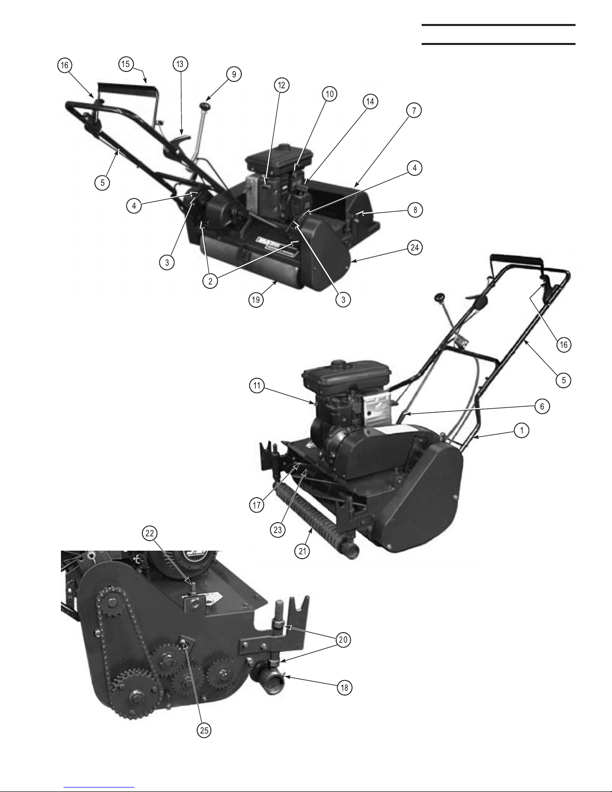
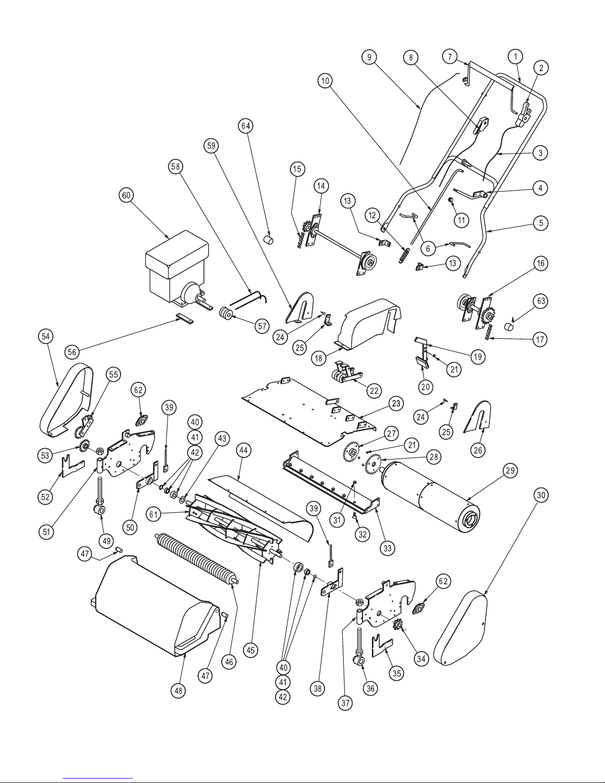
1 400115 HANDLE BAR, Upper 1
2 09201 CONTROL, Reel 1
3 09200 CONTROL CABLE, Reel 1
4 200509 LEVER, Brake 1
5 400114 HANDLE BAR, Lower 1
6 08083 ADJUSTMENT ROD, Handle Bar 2
7 400201 BAIL 1
8 09198 CONTROL, Throttle 1
9 09199 CONTROL, Drive 1
10 08085 ROD, Brake 1
11 07024 KNOB, Brake Lever 1
12 04520 SPRING, Brake Rod 1
13 400069 RETAINER, Clutch Cable 1
14 400040 COUNTERSHAFT, See Figure 2 1
15 07503 CHAIN, Roller 1
16 400041 COUNTERSHAFT, See Figure 3 1
17 07502 CHAIN, Reel 1
18 400205 GUARD, Clutch 1
19 400024 PIVOT, Brake 1
20 400017 BRAKE 1
21 200676 BUSHING 4
22 400100 CLUTCH, See Figure 5 1
23 400102 PLATE, Top 1
24 05002 PIN, Handle Bar 2
25 400117 BRACKET, Handle Bar Pin 2
26 400319 GUARD, Left Inside 1
27 400093 GEAR, Roller, 36 Tooth 1
28 400092 SPROCKET, Roller, 28 Tooth 1
29 400038 ROLLER ASSEMBLY, Rear, See Figure 4 1
30 400070 GUARD, Left Side 1
31 201802 NUT, Bed Bar 8
32 02109 SCREW, Bed Bar 8
33 302311 BED BAR, with Bedknife 1
302310 BEDKNIFE, Only 1
34 03114 SPROCKET, Reel, 11 Tooth 1
35 400029 BRACKET, Basket, Left Side 1
36 302846 ADJUSTER, Roller, Left 1
37 400061 SIDE PLATE, Left 1
38 400035 CARRIER, Reel, Left 1
39 400008 ADJUSTER, Reel 2
40 06102 BEARING, Tapered Roller 2
41 06121 RACE, Tapered Roller 2
42 03508 SEAL, Reel Carrier 2
43 201437 TAKE-UP, Reel Bearing 2
44 400094 SHIELD, Front Throw 1
45 302491 REEL, 6 Blade 1
302738 REEL, 8 Blade 1
46 400322 ROLLER, Shallow Groove 1
400442 ROLLER, Deep Groove 1
47 400460 PIN, Basket 2
48 07338 BASKET 1
49 302847 ADJUSTER, Roller, Right 1
50 400034 CARRIER, Reel, Right 1
51 400075 SIDE PLATE, Right 1
52 400030 BRACKET, Basket, Right 1
53 400078 GEAR, Reel, 24 Tooth 1
54 400071 GUARD, Right 1
55 400104 BACKLAP GEARS, See Figure 6 1
56 400471 ADJUSTING PLATE, Engine 1
57 03638 PULLEY, Engine, Inside 1
58 03939 BELT, Gates #6832 2
59 400320 GUARD, Right Inside 1
60 07513 ENGINE, Briggs & Stratton, 3.5 H.P. 1
61 200256 ADJUSTING SCREW & NUT 1
62 06136 BEARING 6
FIGURE 1 MAIN ASSEMBLY
Item DescriptionPart No. Qty.

IM25OM-1/2000-250
10
___________________________________________________________________________________________________________________________________________
____________________________________________________________________________________________________________________________________________
FIGURE 2GROUND DRIVE COUNTERSHAFT ASSEMBLY, 400040
Item DescriptionPart No. Qty.
1 03117 SPROCKET,14 Tooth 1
2 03634 PULLEY 1
3 06136 BEARING 2
4 400020 PLATE, Bearing Carrier, Short 1
5 400063 PLATE, Bearing Carrier, Long 1
6 400069 RETAINER,ClutchCable 1
7 400095 COUNTERSHAFT,RollerDrive 1
8 202436 Key, #9 Woodruff 1

NATIONAL IM25 Infield Mower
®
11
___________________________________________________________________________________________________________________________________________
___________________________________________________________________________________________________________________________________________
FIGURE 3REEL DRIVE COUNTERSHAFT, 400041
Item DescriptionPart No. Qty.
1 202839 SPROCKET,24Tooth 1
2 03634 PULLEY 1
3 06136 BEARING 2
4 400020 PLATE, Bearing Carrier, Short 1
5 400063 PLATE, Bearing Carrier, Long 1
6 400069 RETAINER,ClutchCable 1
7 400096 COUNTERSHAFT,ReelDrive 1
8 202436 KEY, #9 Woodruff 1

IM25OM-1/2000-250
12
___________________________________________________________________________________________________________________________________________
_______________________________________________________________________________________________________________________________________
FIGURE 4REAR ROLLER ASSEMBLY, 400038
Item DescriptionPart No. Qty.
1 400037 TUBE, Roller 2
2 400097 SHAFT,Roller 1
3 400013 RING, Pinion 2
4 400014 RETAINER,Pinion 2
5 04531 SPRING, Pinion Pawl 2
6 09077 PAWL, Pinion 2
7 202436 KEY, #9 Woodruff 2
8 06140 BEARING 4
9 02502 WASHER 1

NATIONAL IM25 Infield Mower
®
13
___________________________________________________________________________________________________________________________________________
FIGURE 5CLUTCH ASSEMBLY, 400100
Item DescriptionPart No. Qty.
1 400044 BRACKET,Mowing Clutch 1
2 400099 BRACKET, Clutch Mount 1
3 400080 BRACKET,TransportClutch 1
4 03608 PULLEY 2
5 200676 BUSHING 2

IM25OM-1/2000-250
14
___________________________________________________________________________________________________________________________________________
___________________________________________________________________________________________________________________________________________
___________________________________________________________________________________________________________________________________________
FIGURE 6BACKLAP GEAR ASSEMBLY, 400104
Item DescriptionPart No. Qty.
1 400106 BRACKET 1
2 400105 GEAR, with Bushing, 24 Tooth 2
3 02502 WASHER 4
4 04020 LOCKRING,3/4 2
5 400109 PIN, Gear 2
6 02148 SCREW, Flat Head Slotted, 5/1618 X 3/4 2
7 200676 BUSHING 1
8 02034 CAPSCREW, 3/816 X 3/4 1
9 02403 WASHER, Flat, 3/8 1
10 02303 LOCKWASHER, 3/8 1

NATIONAL IM25 Infield Mower
®
15
NATIONAL MOWER COMPANY
ONE YEAR
LIMITED WARRANTY
For the period of one year from the date of purchase (45 days if the product
is used for rental purposes), National Mower Company will repair or replace free
of charge, for the original purchaser, any part or parts found by inspection to be
defective by our Factory Authorized Service Station or by the Factory at St. Paul,
Minnesota to be defective in material or workmanship or both. All transportation
charges on parts submitted for repair or replacement under this warranty shall be
paid for by the purchaser.
Thiswarranty doesnot include engines,engine partsor tires whichare covered
under separate warranties furnished by their manufacture or supplier.
All service under this warranty will be furnished and performed by our Factory
Authorized Service Stations.
-THERE IS NO OTHER EXPRESS WARRANTY-
IMPLIEDWARRANTIES, INCLUDINGTHOSE OFMERCHANTABILITY AND
FITNESS FOR A PARTICULAR PURPOSE, ARE LIMITED TO ONE YEAR
FROM PURCHASE OR 45 DAYS IF THE PRODUCT IS RENTED AND TO THE
EXTENT PERMITTED BY LAW, ANY AND ALL IMPLIED WARRANTIES ARE
EXCLUDED. THE ABOVE REMEDY OF REPAIR AND REPLACEMENT OF
DEFECTIVE PARTS IS THE PURCHASERS EXCLUSIVE REMEDY FOR ANY
DEFECT,MALFUNCTION OR BREACH OF WARRANTY. LIABILITY FOR
INCIDENTALOR CONSEQUENTIAL DAMAGES UNDERANY AND ALL
WARRANTIESIS EXCLUDED TO THE EXTENT PERMITTED BY LAW.
NATIONAL MOWER COMPANY
700 Raymond Avenue, St. Paul, Minnesota 55414, U.S.A.
Other National Mower Lawn Mower manuals

National Mower
National Mower Triplex-CE DL User manual

National Mower
National Mower I-TRIM User manual

National Mower
National Mower 68 DL TRIPLEX User manual

National Mower
National Mower 99500500-8400 Owner's manual

National Mower
National Mower 2036 User manual

National Mower
National Mower HYDRO 70" TRIPLEX User manual

National Mower
National Mower I-TRIM User manual
Popular Lawn Mower manuals by other brands

Schiller Grounds Care
Schiller Grounds Care Bob-Cat 942297G Operator's manual

Husqvarna
Husqvarna CT135 instruction manual

SHARKS
SHARKS SH 500W Instruction for operation and maintenance

Craftsman
Craftsman ROTARY 917.37712 owner's manual

Husqvarna
Husqvarna 917.37535 owner's manual

EINHELL
EINHELL BG-PM 51 S HW Original operating instructions