FEATURES
HARMONIC
DISTORTION:0.3%
at
ratedoutput
of
20
watts.
0.6%
at25
watts.
INTERMODULATION
DISTORTION:
1%at20
watts,
measured
with
400
cps.
and7 kc.ata
ratio
of
4:1.
FREQUENCY
RESPONSE:±0.1
db
from
20
cps.
to
20
kc.±1db
from
10
cps.
to100kc.
POWER
RESPONSE
AT20
WATTS:
±0.15
db
from
20
cps.
to20kc.±1db
from
10
cps.
to60kc.
HUM
AND
NOISE:
80db
below
20
wattsoutput.
SENSITIVITY:
1.6
volts
for20
wattsoutput.
OUTPUTIMPEDANCE:
8
and
16
ohms
nominal.
INPUT
IMPEDANCE:
500,000ohms.
INPUTLEVELCONTROL:accommodates
a
wide
range
of
input
signal
levels.
RUMBLE
FILTER:built
into
minimizeturntable
rumble
and
noise.
ACCESSORY
OUTLET:
117
volt
AC,3
amp.con-
venienceoutlet
for
energizing
associated
equipment.
PREAMP
COMPARTMENT:contains
multiconnector
wired
to
associated
rear-paneljacks
to
convert
the
Horizon
20toa
single-unitequipment
when
the
Hori-
zon
5
preamp
is
plugged
in.
POWER
INPUT:
117
VAC,50-60cps,
1
amp,
110
watts.
PREPARING
TO
OPERATE
Examine
the
amplifier
immediately
after
unpacking
to
make
certainthat
no
apparentdamage
has
been
in-
curred
duringshipment.
A
cardboard
padis
placed
around
the
tubes
to
protect
them
in
transit.
This
must
be
removed.
Todosoitis
necessary
to
remove
the
cabinet.
Since
the
Horizon
20hasno
operatingcon-
trols,
itmaybe
installed
inany
convenientlocation
so
long
as
there
will
bea
free
circulation
ofairto
allowventilation.
The
above
would
holdtrue
when
the
Horizon
5
preamp
is
used
with
the
amplifier,
pro-
vided
that
the
preamp
is
located
ata
pointremote
from
the
amplifier.
When
the
NationalHorizon
5
preamp
is
plugged
into
the
Horizon
20,the
unitmust
be
installed
with
con-
trol
accessibility
in
mind.
The
attractive
overall
appearance
ofthe
amplifiermakes
it
well
suited
for
useona
tabletop,shelf
orany
convenient
location.
Once
the
input,power
and
speakerconnectionshave
beenmade,
the
Horizon
20
with
the
Horizon
5
preamp
becomes
a
versatile
controlcenter
forthe
custom
high
fidelity
installation.
Ifitis
desired
to
make
this
combination
part
ofa
custom
installation,
refer
tothe
paragraph
on
Cabinet
Installation.
ELECTRICAL
CONNECTIONS
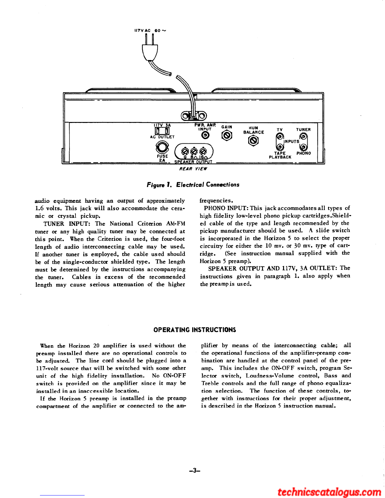
Allthe
input
and
outputconnections
ofthe
Horizon
20
amplifier
are
located
onthe
backdrop
ofthe
chas-
sis.
See
Figure
1.
Connections
tothe
variousjacks
and
terminalsshould
be
made
inthe
following
manner:
1.
HORIZON
20
AMPLIFIER
WITHOUT
HORIZON
5
PREAMP
PWR.
AMP.INPUT:
The
output
ofthe
National
Criterion
or
similar
AM-FM
tuner
orthe
output
ofa
preamp
otherthan
the
Horizon
5 is
connected
to
this
jack.Singleconductorshielded
cable
must
be
used,
the
lengthdictated
bythe
recommendationsaccompany-
ing
the
particularequipment.
Associated
equipment
should
have
an
output
level
of1.6
volts
or
more.
All
other
jacks
are
unused.
SPEAKER
OUTPUT:
A
highfidelityloudspeaker
system
having
an
impedance
of
either
8 or16
ohms
may
be
connected
to
these
terminals.
The
terminal
marked
G isthe
common
connection
andmaybe
grounded
if
desired.
Shieldedcable
isnot
required
for
speakerconnections
andthe
length
isnot
critical.
Number
18
wire
(size
of
ordinarylampcord),
or
larger,
is
recommended.
117V
3A
OUTLET:
This
convenienceoutlet
is
supplied
forthe
purpose
of
providinginputvoltage
for
otherunits
ofthe
system
as
desired.
Itis
ener-
gized
when
the
amplifier
is
pluggedinto
the
117-volt
line.
2.
HORIZON
20
AMPLIFIER
WITH
HORIZON
5
PREAMP
PWR.
AMP.INPUT:
When
the
Horizon
5
preamp
is
used
with
the
Horizon
20,
eitherpluggedinto
the
unit
or
connected
by
means
ofan
interconnecting
cable,
the
Pwr.Amp.Inputjack
isnot
used.
The
interconnectingcablecompletewithmatingconnec-
tors
maybe
procured
in
either
4 or
15-footlengths.
When
the
interconnecting
cable
is
used,
remove
one
of
the
thumbscrews
from
the
preamp
compartment
coverplate
and
thread
the
screwinto
the
tappedhole
atthe
rightedge
ofthe
preampcompartment.
This
must
be
done
in
order
to
close
the
interlockswitch.
TV
INPUT:
AnyTV
tunerhaving
an
output
of1.6
volts
or
more
maybe
connected
to
this
jack.
This
jack
will
also
accommodate
the
standardhigh-level
ceramic
or
crystaltypephonopickup.Shieldedcable
must
be
used.
TAPE
PLAYBACK
INPUT:
A
tapereproducing
unit
maybe
connected
to
this
jack,
orany
piece
of
-2-