The
National
INSTRUCTION
BOOK
FOR
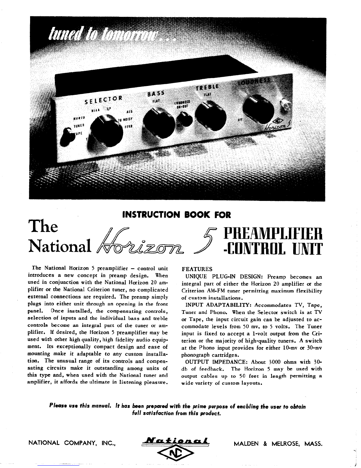
The
National
Horizon
5
preamplifier
—
controlunit
introduces
a new
concept
in
preamp
design.
When
used
in
conjunctionwith
the
National
Horizon
20am-
plifier
orthe
NationalCriteriontuner,
no
complicated
externalconnections
are
required.
The
preamp
simply
plugsintoeitherunitthrough
an
opening
inthe
front
panel.
Once
installed,
the
compensating
controls,
selection
of
inputs
andthe
individual
bass
and
treble
controlsbecome
an
integralpart
ofthe
tuner
oram-
plifier.
If
desired,
the
Horizon
5
preamplifier
maybe
usedwithotherhighquality,highfidelityaudioequip-
ment.
Its
exceptionallycompactdesign
and
ease
of
mountingmake
it
adaptable
toany
custom
installa-
tion.
The
unusualrange
ofits
controls
and
compen-
sating
circuits
make
it
outstanding
among
units
of
this
typeand,
when
usedwith
the
Nationaltuner
and
amplifier,
it
affords
the
ultimate
in
listening
pleasure.
PREAMPLIFIER
-CONTROL
UNIT
FEATURES
UNIQUE
PLUG-INDESIGN:Preampbecomes
an
integralpart
of
either
the
Horizon
20
amplifier
orthe
Criterion
AM-FM
tunerpermitting
maximum
flexibility
of
custom
installations.
INPUTADAPTABILITY:Accommodates
TV,
Tape,
Tuner
and
Phono.
When
the
Selectorswitch
isatTV
or
Tape,
the
inputcircuitgain
canbe
adjusted
toac-
commodate
levels
from
50mv,to5
volts.
The
Tuner
input
is
fixed
to
accept
a
1-volt
output
from
the
Cri-
terion
orthe
majority
of
high-qualitytuners.
A
switch
atthe
Phonoinputprovides
for
either
10-mv
or
30-mv
phonograph
cartridges.
OUTPUT
IMPEDANCE:About3000ohmswith
30-
db
of
feedback.
The
Horizon
5 maybe
usedwith
output
cables
upto50
feet
in
lengthpermitting
a
wide
variety
of
custom
layouts.
Please
use
this manual.
It
has
been prepared
with
the
prime purpose
of
enabling
the
user
to
obtain
full
satisfaction
from
this product.
NATIONAL
COMPANY,
INC.,
MAIDEN
&
MELROSE,MASS.