Vector Series – NAPI80 Site Interface PWB Installation Procedure Page 1
IS09006A Issue 0.2
IS09006A – Vector Series – NAPI80 Site Interface
PWB Installation Procedure
INFORMATION SHEET
1 INTRODUCTION
This document describes how to install the
NAPI80 Site Interface PWB in a Vector
series transmitter.
1.1 Reason for Modification
The site interface PWB is an interface
between a Vector series transmitter and
parallel monitor and control points
provided to the user. This interface allows
the user to remotely monitor and control
parts of the transmitter using their own
equipment or a Nautel ECMP (extended
control/monitor panel).
1.2 Equipment Affected
This procedure applies to Vector-LP series
NDB/DGPS transmitters (VR125, VR250,
VRD200 and VRD375) and Vector HP
NDB transmitters (VR500, VR1000 and
VR2000).
1.3 Responsibility for
Implementation of Procedure
This procedure should be carried out by
qualified station maintenance personnel
who are familiar with the Vector series
transmitter.
1.4 Scheduling
This procedure may be implemented at
the convenience of station maintenance
personnel.
1.5 Manpower Requirements
It is estimated that implementing this
modification will require 20 minutes to
complete for Vector-LP transmitters and
one hour to complete for Vector-HP
transmitters.
1.6 Special Tools/Test Equipment
Standard hand tools (screwdriver,
nutdriver, etc.) are required.
2 PRELIMINARY CHECKS
Ensure the supplied installation kit (Nautel
Part # 195-2085) includes an NAPI80 Site
Interface PWB (with 20-pin ribbon cable
assembly), and associated securing
hardware. See Table 1 for a complete
parts list.
Table 1: Parts List – Site Interface
Installation Kit (Nautel Part # 195-2085)
Qty Description
1 IS09006A (Documentation)
8 HMSP12 Screw, Pan, Phil, M3x0.5x16 lg
8 HMW10 Washer, External Tooth, M3
8 HMP05 Pillar, M3x0.5, 8mm lg,6mm hex brass
8 HMW02 Washer, Plain, M3
8 HMW32 Washer, Split, M3
8 HMN02 Nut, Hex, M3x0.5
8 HMSP09F Screw, Pan, Phil, M3x0.5x8 lg
1 NAPI80 Site Interface PWB (includes 20-pin
ribbon cable assembly)
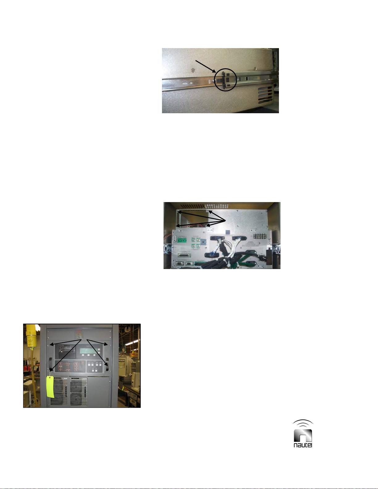
3 INSTALLATION
Install the site interface PWB in the Vector
transmitter as follows:
NOTES
To install the site interface PWB in a
Vector-HP transmitter (see paragraph 3.1)
you be required to remove the exciter/
control assembly from the rack.
To install the site interface PWB in a
Vector-LP transmitter (see paragraph 3.2)
you will need access to the rear of the
transmitter’s front door.
Parts from the site interface installation kit
(Nautel Part # 195-2085, see Table 1) are
referenced in the following procedure.