Fostex APPENDIX User manual

This appendix is the operation manual for the recorder with the Model 8345
TC/SYNC card installed. If you use the recorder with the Model 8345 installed,
read this appendix, instead of the operation manual included in the Model
8345 package.
<Installation of the optional card>
The TC/SYNC card should be installed into the recorder at a FOSTEX service
station. Do not try to install the card by yourself. Ask your local FOSTEX dealer
for the installation after purchasing the Model 8345.
<Notes when requesting the installation>
There is the possibility of damaging the hard disk when transporting the re-
corder. Before transporting the recorder to our service department for the
installation of the TC/SYNC card, remove the hard disk from the recorder. Be
sure to keep the removed hard disk carefully.
APPENDIX
<Operation manual for the recorder with the Model 8345 TC/SYNC card installed>

2
APPENDIX (Operation manual for the recorder with the Model 8345 TC/SYNC card installed)
Contents of Appendix
Names and Functions.........................................................................3
Introduction..........................................................................................4
Additional features..............................................................................4
Operations for the additional SETUP menu......................................4
“Ref. TC ?” menu setting.......................................................................4
“Clock Sel ?” menu setting....................................................................5
“Sync Preset ?” menu setting................................................................5
“Virtual LTC ?” menu setting................................................................6
“Offset Disp ?” menu setting................................................................6
Generator Setup..................................................................................7
How to enter the Generator Setup mode............................................7
Setting the timecode recording mode.................................................7
Editing the internal generator timecode............................................8
Force jamming to external timecode...................................................8
Selecting the output timecode.............................................................8
Editing the chase offset.........................................................................9
Erasing the recorded timecode............................................................9
Chase sync to external timecode.....................................................10
Synchronization to word clock or video signal...............................11
Connection to a digital mixing console...........................................11
Contorl from a video editor (RS-422)...............................................13
3
APPENDIX (Operation manual for the recorder with the Model 8345 TC/SYNC card installed)
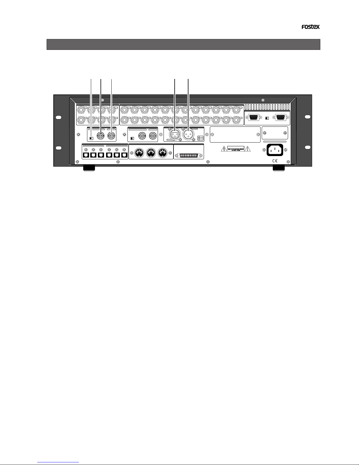
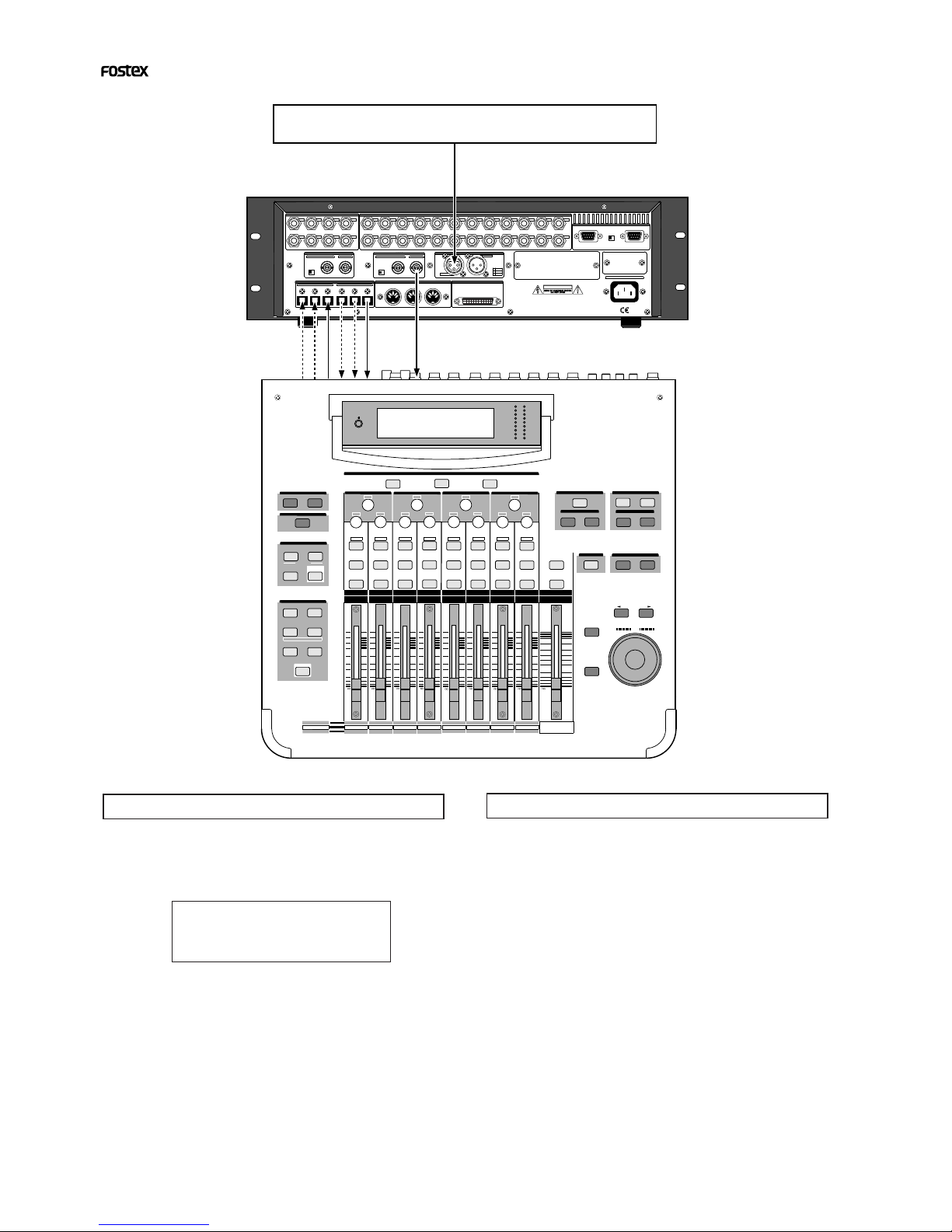
Names and Functions
1. VIDEO IN termination switch
(75-ohmtermination ON/OFF)
Used to terminate the VIDEO INPUT signal and
usually set to ON.
2. VIDEO IN connector (BNC connector)
Receives an external video sync signal (inter-
lace or composite) when synchronizing the
recorder to a video sync signal.
3. VIDEO THRU connector (BNC connector)
Outputs the video sync signal received from
the VIDEO INPUT connector.
4. TIME CODE INPUT connector
(XLR-3-31 or equivalent, balanced, pin #2 hot)
Receives external time code (LTC).
5. TIME CODE OUTPUT connector
(XLR-3-32 or equivalent, balanced, pin #2 hot)
Outputs an LTC from the recorder (equiva-
lent to the MTC displayed on the panel) or
time code from the internal TC generator.
75Ω
WORD
OUTPUTINPUT
OUTPUT
DATA
16 - 9
24 - 17 8 - 1
100Ω
RS422
THRU
AC-IN
INPUT
16 - 9
24 - 17 8 - 1
SCSI
ON OFF
REMOTE
MIDI
INPUT THRU
OUTPUT
1
2
34
5678
1
234
13141516
5
6
7
8
1718
19
20
9
10
11
12
21
22
2324
NE PAS OUVRIR
CAUTION
AVIS:
RISQUE DE CHOC ELECTRIQUE
WARNING:
TO REDUCE THE RISK OF FIRE OR ELECTRIC
SHOCK, DO NOT EXPOSE THIS EQUIPMENT
TO RAIN OR MOISTURE.
ANALOG INPUT BALANCE [ +4dBu ] / UNBALANCE [ -10dBv ] ANALOG OUTPUT BALANCE [ +4dBu ] / UNBALANCE [ -10dBv ]
ON OFF
INPUT
OUTPUT
HOT
GND
COLD
1
2
3
TIME CODE
THRUINPUT
ON OFF
75Ω
DATA MIDI
WORD
SCSI
REMOTE
ANALOG OUTPUT BALANCE [ +4dBu ] / UNBALANCE [ -10dBV ]
ANALOG INPUT BALANCE [ +4dBu ] / UNBALANCE [ -10dBV ]
VIDEO TIME CODE
5
4
3
21
4
APPENDIX (Operation manual for the recorder with the Model 8345 TC/SYNC card installed)
The Model 8345 is a TC/SYNC card designed as an
option for digital multitrack recorders.
By installing the TC/SYNC card into the recorder,
the recorder can synchronize to external LTC or
video signal, as well as an external word clock. So
you can use the recorder synchronized with video
machines in video post production studios where
the synchronization between audio and video is in-
dispensable, or make digital sound recordings in a
system using a digital mixing console.
By installing the Model 8345 into the recorder, the
following SETUP menus and GEN setup function are
added. These SETUP menus are used when the re-
corder is synchronized to an external LTC or locked
to a video signal.
1. SETUP mode “Ref. TC ?” menu
This menu selects the reference time code used as a mas-
ter time code for the recorder.
The reference time code can be selected between MTC
(MIDI time code) and LTC according to the incoming time
code. The default setting after formatting a disk is “LTC”.
2. SETUP mode “Clock Sel ?” menu
This menu selects the reference clock of the recorder with
the 8345.
If the 8345 is not installed, you can select the reference
clock from “Int”, “Auto” and “Word”.
If the 8345 is installed, “Video” also can be the reference
clock in addition to the three options above.
3. SETUP mode “Sync Preset ?” menu
This menu is effective when the recorder with the 8345
installed is used in sync with a digital mixing console.
You can select from some preset options according to your
system to get the best synchronization performance.
4. SETUP mode “Virtual LTC ?” menu
This menu selects whether recording/playback of the vir-
tual LTC is enabled or disabled. The default setting is
[Ena.] (Enabled).
5. SETUP mode “Offset Disp ?” menu
This menu selects whether or not displaying the real off-
set between the incoming reference time code (LTC or MTC)
and the displayed MTC (output LTC).
The real offset is displayed instead of REMAIN when dis-
playing the MTC.
6. GENERATOR setup functions
The GENERATOR setup functions allows recording/eras-
ing an external or internal (generator) time code, force-
jamming to external time code, setting the LTC output,
and setting the chase offset value between incoming time
code and the MTC.
Operations for the additional SETUP menu
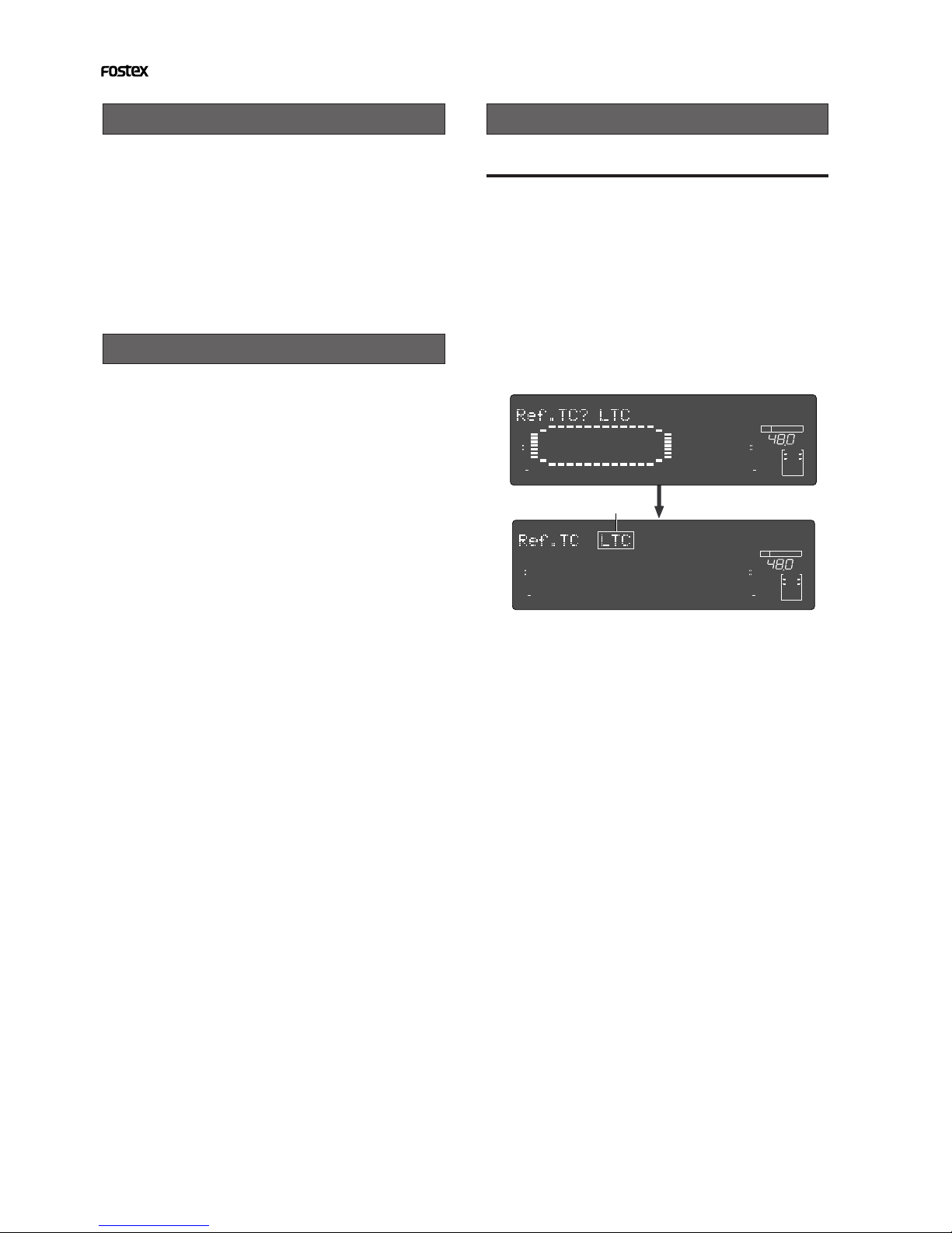
"Ref. TC ?" menu setting
Introduction
Additional features
1. Turn on the power of the recorder.
2.Press the [SETUP] key while the recorder is
stopped to show the SETUP menu.
3.Select the “Ref. TC?” menu by using the [JOG] dial
and press the [EXECUTE/YES] key.
The reference time code currently selected starts flash-
ing (the default reference time code setting when the
Model 8345 is installed is “LTC”).
The outlined box surrounds the flashing item on the
display.
4.Select the reference time code by using the [JOG]
dial.
You can select between “LTC” and “MTC” (MIDI time
code).
5. After selecting the reference time code, press the
[EXECUTE/YES] key.
The selected reference time code is confirmed (set) and
the display changes to the similar one to the upper
example in step 3 above where “?” flashes.
6. Press the [EXIT/NO] key (or the [STOP] button) to
exit the SETUP mode.
You can check the time information of the incoming
reference time code in the front panel display of the
recorder.
See "Chase sync to external time code" below for details.
∞
42
OL
0
30
24
18
12
9
6
3
kHz
24
FS
BIT
SETUP
24
∞
42
OL
0
30
24
18
12
9
6
3
2322
21
20
19
18
17
1615141312
11
10
98765
4
3
2
1
CLOCK
INT
∞
42
OL
0
30
24
18
12
9
6
3
kHz
24
FS
BIT
SETUP
24
∞
42
OL
0
30
24
18
12
9
6
3
2322
21
20
19
18
17
1615141312
11
10
98765
4
3
2
1
CLOCK
INT
Flashing

5
APPENDIX (Operation manual for the recorder with the Model 8345 TC/SYNC card installed)
4. Select the desired reference clock by using the
[JOG] dial.
You can select from “Auto”, “Word” and “Video” as well
as “Int”. The following table shows the function of each
option.
"Clock Sel ?" menu setting
Reference clock Function
Auto
Int
Word
Video
The reference clock is automatically selected
from among available clocks according to the
following order of priority; Word, Video and
Int.
The 8345 references to the internal clock.
The 8345 references to an external word clock.
The 8345 references to an external video clock.
4. Select the desired sync preset combination by
using the [JOG] dial from the followings;
The following table shows the function of each preset.
"Sync Preset ?" menu setting
Preset item
Int. Vari
Word Free
Video Vari
Video Free
Ana.
adat
Ana.
adat
Int. Free
Ana.
adat
Ana.
adat
Ana.
adat
D. in ? setting
Not assigned
adat ;Async
Not assigned
Not assigned
Not assigned
Not assigned
adat ;Async
adat ;Async
adat ;Async
adat ;Async
8345
Clock Slave
Type
Int
Int
Word
Video
Video
Vari
Vari
Free
Free
Free
Execute step 1 and 2 in "Ref. TC ?" menu setting"
described above.
3. Select the “Clock Sel?” menu by using the [JOG]
dial and press the [EXECUTE/YES] key.
The reference clock currently selected starts flashing (the
default reference clock setting when the Model 8345 is
installed is “INT”).
5. After selecting the reference clock, press the
[EXECUTE/YES] key.
The selected reference clock is confirmed (set) and the
display changes to the similar one to the upper example
in step 3 above where “?” flashes.
6. Press the [EXIT/NO] key (or the [STOP] button) to
exit the SETUP mode.
Execute step 1 and 2 in "Ref. TC ?" menu setting"
described earlier.
3. Select the “Sync Preset ?” menu by using the
[JOG] dial and press the [EXECUTE/YES] key.
The sync preset setting currently selected is shown (the
default setting when the Model 8345 is installed is “Int.
Vari? Ana.”).
5. After selecting the preset, press the [EXECUTE/
YES] key.
The selected preset is confirmed (set) and the display
changes to the similar one to the upper example in step
3 above where “?” flashes.
6. Press the [EXIT/NO] key (or the [STOP] button) to
exit the SETUP mode.
∞
42
OL
0
30
24
18
12
9
6
3
kHz
24
FS
BIT
SETUP
24
∞
42
OL
0
30
24
18
12
9
6
3
2322
21
20
19
18
17
1615141312
11
10
98765
4
3
2
1
CLOCK
INT
∞
42
OL
0
30
24
18
12
9
6
3
kHz
24
FS
BIT
SETUP
24
∞
42
OL
0
30
24
18
12
9
6
3
2322
21
20
19
18
17
1615141312
11
10
98765
4
3
2
1
CLOCK
INT
∞
42
OL
0
30
24
18
12
9
6
3
kHz
24
FS
BIT
SETUP
24
∞
42
OL
0
30
24
18
12
9
6
3
2322
21
20
19
18
17
1615141312
11
10
98765
4
3
2
1
CLOCK
INT
∞
42
OL
0
30
24
18
12
9
6
3
kHz
24
FS
BIT
SETUP
24
∞
42
OL
0
30
24
18
12
9
6
3
2322
21
20
19
18
17
1615141312
11
10
98765
4
3
2
1
CLOCK
INT
Flashing Flashing

6
APPENDIX (Operation manual for the recorder with the Model 8345 TC/SYNC card installed)
"Virtual LTC?" menu setting
4. Select “Ena.” or “Dis.” by using the [JOG] dial.
Selection Function
Ena.
(Enable) Enables recording/playback of the virtual LTC.
Dis.
(Disable)
Disables recording/playback of the virtual LTC.
This setting is used when you want to chase the
recorder using only the MTC offset setting, ignor-
ing the recorded LTC.
With this setting, the TIME CODE OUT terminal
outputs MTC or LTC with the MTC offset.
"Offset Disp?" menu setting
4. Select “Off” or “On” by using the [JOG] dial.
Selection Function
Off The real-offset value is not displayed.
On
The real-offset value is displayed instead of the
REMAIN time when the time base is set to MTC
If you press the [STORE] key, the display shows
[Catch Offset!] for a second, then changes to the
edit mode display of the chase offset which will
be explained in "GENERATOR Setup" later.
After editing the chase offset, pressing the [EX-
ECUTE/YES] key updates the real-offset value.
5. After selecting “Off” or “On”, press the [EXECUTE/
YES] key.
6. Press the [EXIT/NO] key (or the [STOP] button) to
exit the SETUP mode.
Execute step 1 and 2 in ""Ref. TC ?" menu setting"
described earlier.
3. Select the “Virtual LTC?” menu by using the [JOG]
dial and press the [EXECUTE/YES] key.
The current setting is flashing (the default setting when
the Model 8345 is installed is “Ena.” (enable)).
5. After selecting “Ena.” or “Dis.”, press the
[EXECUTE/YES] key.
6. Press the [EXIT/NO] key (or the [STOP] button) to
exit the SETUP mode.
<CAUTION>
Do not set the Virtual LTC to “Ena.” for a disc on which
data was recorded by the FDMS-3 Ver. 1.0 format using
the machines such as D-160 and D108. Otherwise, it
may cause malfunction because the FDMS-3 Ver. 1.0
does not support the Virtual LTC.
Execute step 1 and 2 in ""Ref. TC ?" menu setting"
described earlier.
3. Select the “Offset Disp?” menu by using the [JOG]
dial and press the [EXECUTE/YES] key.
The current setting is flashing (the default setting when
the Model 8345 is installed is “Off”).
<CAUTION>
When the power is turned off, the Offset Disp mode
returns to the default setting (“Off”).
∞
42
OL
0
30
24
18
12
9
6
3
kHz
24
FS
BIT
SETUP
24
∞
42
OL
0
30
24
18
12
9
6
3
2322
21
20
19
18
17
1615141312
11
10
98765
4
3
2
1
CLOCK
INT
∞
42
OL
0
30
24
18
12
9
6
3
kHz
24
FS
BIT
SETUP
24
∞
42
OL
0
30
24
18
12
9
6
3
2322
21
20
19
18
17
1615141312
11
10
98765
4
3
2
1
CLOCK
INT
∞
42
OL
0
30
24
18
12
9
6
3
kHz
24
FS
BIT
SETUP
24
∞
42
OL
0
30
24
18
12
9
6
3
2322
21
20
19
18
17
1615141312
11
10
98765
4
3
2
1
CLOCK
INT
∞
42
OL
0
30
24
18
12
9
6
3
kHz
24
FS
BIT
SETUP
24
∞
42
OL
0
30
24
18
12
9
6
3
2322
21
20
19
18
17
1615141312
11
10
98765
4
3
2
1
CLOCK
INT
Flashing Flashing

7
APPENDIX (Operation manual for the recorder with the Model 8345 TC/SYNC card installed)
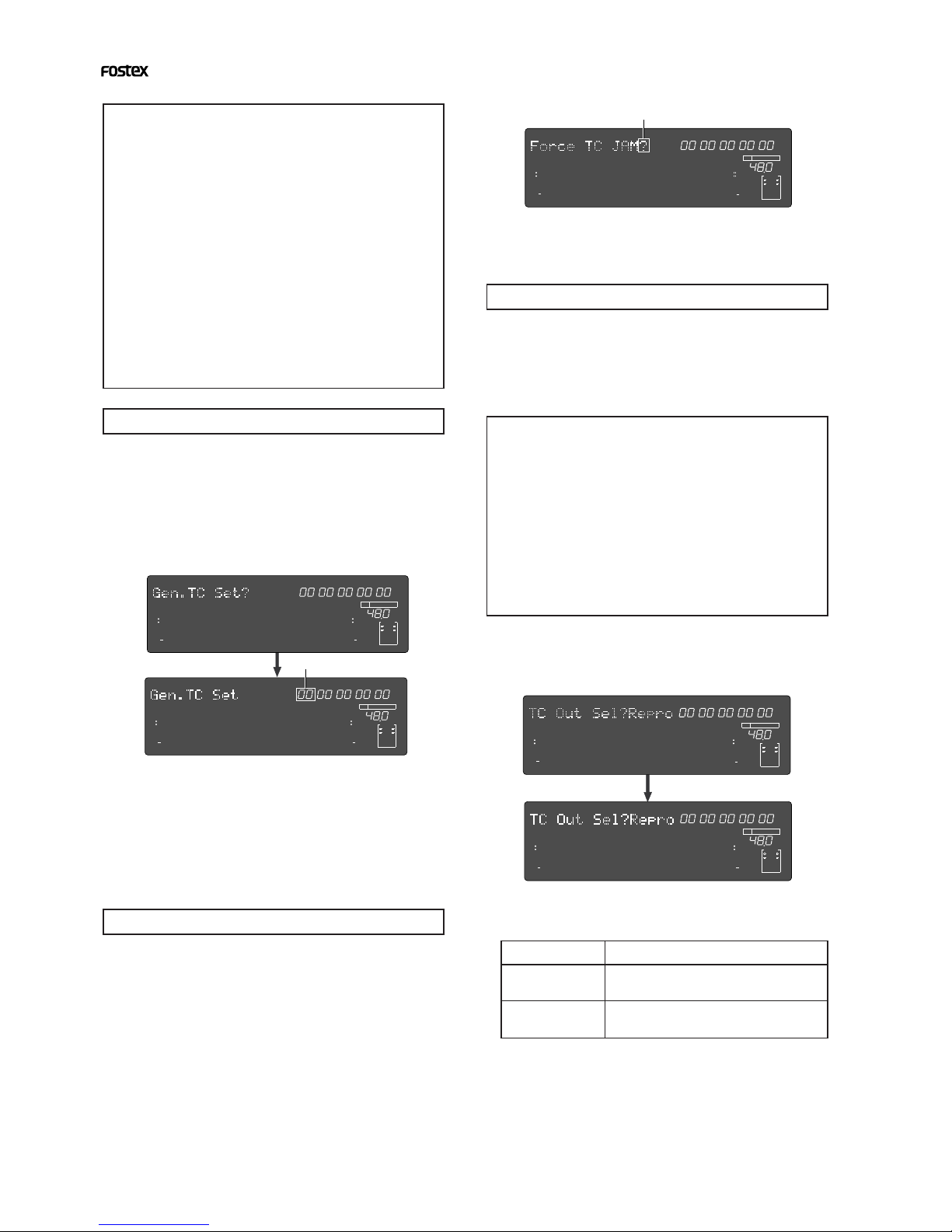
Generator Setup
By installing the Model 8345 TC/SYNC card into the recorder, the Generator Setup functions acti-
vate and the following features are available.
How to enter the Generator Setup mode
Menu for setting the
time code recording
mode
Menu for editing the
time code of the in-
ternal time code
generator
Menu for force jam-
ming to external
time code
Display of internally
generated time code
Menu for selecting
the output time code
Menu for editing the
chase offset between
external time code
and MTC
Menu for erasing all
the recorded time
code
Setting the time code recording mode
Recording mode
Rec Run
Free Run
Ext Run
24H Run
Time code that is continuous with the time
code previously recorded will be recorded.
This mode is also useful to re-record a dis-
continuous time code.
Time code generated by the internal gen-
erator will be recorded.
External time code will be recorded.
Time code generated by the internal gen-
erator will be recorded from the current
time of the recorder's internal clock.
Function
<CAUTION>
The 8345 does not record all time code information. It
records only the ABS time at the recording start point
and the time code offset value. Therefore, if you record
discontinuous time code in the middle, it cannot recog-
nize it. Also note that because the user's bit at the re-
cording start point is maintained, the 8345 cannot rec-
ognize user's bit change in the middle.
2. Use the [JOG] dial to display the desired
recording mode.
You can choose from 4 recording modes available.
<CAUTION>
When you create a new program using the program se-
lect function, the LTC with the same MTC offset (which
you can see in the [MTC offset?] menu of the Setup mode)
as the current program is recorded in the new program.
Therefore, if you use the same LTC with the new pro-
gram, you do not need to re-record LTC.
1. Recording/playback of external or internally generated time code
2. Force jam to external time code
3. Outputting the internally generated or recorded time code
4. Setting of the chase offset between external time code and MTC
1. Press the [SETUP] key while holding down the
[SHIFT] key.
The recorder enters the Generator Setup mode in which
the following menus are available. The display will show
“TC Gen.?Rec Run” (the default) when you first select
the Generator Setup mode. However, from the second
time, the menu selected last time will appear.
By rotating the [JOG] dial, the menus of the Generator
Setup mode appear one after the other.
1. Select “TC Gen.? Rec Run” of the Generator
Setup mode and press the [EXECUTE/YES] key.
The recording mode currently selected starts flashing,
showing that you are now ready to select the desired
recording mode.
3.Press the [EXECUTE/YES] key after selecting the
recording mode.
FSMH
∞
42
OL
0
30
24
18
12
9
6
3
kHz
24
FS
BIT
SF
24
∞
42
OL
0
30
24
18
12
9
6
3
GEN
2322
21
20
19
18
17
1615141312
11
10
98765
4
3
2
1
CLOCK
INT
FSMH
∞
42
OL
0
30
24
18
12
9
6
3
kHz
24
FS
BIT
SF
24
∞
42
OL
0
30
24
18
12
9
6
3
GEN
2322
21
20
19
18
17
1615141312
11
10
98765
4
3
2
1
CLOCK
INT
FSMH
∞
42
OL
0
30
24
18
12
9
6
3
kHz
24
FS
BIT
SF
24
∞
42
OL
0
30
24
18
12
9
6
3
GEN
2322
21
20
19
18
17
1615141312
11
10
98765
4
3
2
1
CLOCK
INT
FSMH
∞
42
OL
0
30
24
18
12
9
6
3
kHz
24
FS
BIT
SF
24
∞
42
OL
0
30
24
18
12
9
6
3
GEN
2322
21
20
19
18
17
1615141312
11
10
98765
4
3
2
1
CLOCK
INT
FSMH
∞
42
OL
0
30
24
18
12
9
6
3
kHz
24
FS
BIT
SF
24
∞
42
OL
0
30
24
18
12
9
6
3
CHASE OFFSET
2322
21
20
19
18
17
1615141312
11
10
98765
4
3
2
1
CLOCK
INT
FSMH
∞
42
OL
0
30
24
18
12
9
6
3
kHz
24
FS
BIT
SF
24
∞
42
OL
0
30
24
18
12
9
6
3
CHASE OFFSET
2322
21
20
19
18
17
1615141312
11
10
98765
4
3
2
1
CLOCK
INT
∞
42
OL
0
30
24
18
12
9
6
3
kHz
24
FS
BIT 24
∞
42
OL
0
30
24
18
12
9
6
3
2322
21
20
19
18
17
1615141312
11
10
98765
4
3
2
1
CLOCK
INT
FSMH
∞
42
OL
0
30
24
18
12
9
6
3
kHz
24
FS
BIT
SF
24
∞
42
OL
0
30
24
18
12
9
6
3
GEN
2322
21
20
19
18
17
1615141312
11
10
98765
4
3
2
1
CLOCK
INT
FSMH
∞
42
OL
0
30
24
18
12
9
6
3
kHz
24
FS
BIT
SF
24
∞
42
OL
0
30
24
18
12
9
6
3
GEN
2322
21
20
19
18
17
1615141312
11
10
98765
4
3
2
1
CLOCK
INT
Flashing
8
APPENDIX (Operation manual for the recorder with the Model 8345 TC/SYNC card installed)
Force jamming to external time code
Selecting the output time code
Output setting
Repro
Gen.
Reproduced time code
Internal generator time code
1. Select “TC Out Sel?” (“?” flashes) of the Generator
Setup mode and press the [EXECUTE/YES] key.
The current output setting flashes (the default setting is
“Repro”).
<CAUTION>
• While time code is output, the recorder's vari pitch
and word sync functions are prohibited.
Note that the time code output setting is available
only when an "Async" mode (“adat:Async” or
“SPDIF:Async”) is selected in the “D. in?” menu of the
Setup mode.
Also note that if you execute a program change, etc.
the generator stops time code generation.
• The “TC Out Sel?” setting returns to the default
“Repro” when turning the power off.
3. After the setting is completed, press the
[EXECUTE/YES] key.
4. Press the [EXIT/NO] (or the [STOP] button) to exit
the Generator Setup mode.
Output timecode
Editing the internal generator time code
<How to record time code>
After setting the time code recording mode de-
scribed above, record timecode by the following
procedure.
1.Press the [EDIT] key while holding down the [SHIFT]
key to turn TC READY on (the TC READY indicator
will flash).
2.Press the [PLAY] button while holding down the
[RECORD] button (the TC READY indicator will light).
Unlike audio signal recording, you do not need
to arm a track for time code.
Also note that recording time code does not con-
sume the hard disk space.
To erase all the time code information, see "Eras-
ing the recorded timecode" described later.
2. Use the [SHUTTLE] dial to move the editing point
(which is flashing), and use the [JOG] dial to set
the numeric value.
Up to 23h59m59s**f (** = current frame rate - 1) can be
set.
3. After editing is completed, press the [EXECUTE/
YES] key. 2. Use the [JOG] dial to select “Repro” or “Gen.”.
The time code output from the TIME CODE OUT
terminal changes according to the setting.
1. Select “Gen TC Set” of the Generator Setup mode
and press the [EXECUTE/YES] key.
The current internal generator time code is displayed
and you are now ready to edit the time.
Editing the internal generator time code can be done
only when the timecode recording mode (described
above) is set to “Free Run”.
Force jamming to external time code can be done
only when the time code recording mode (described
above) is set to “Free Run”. Note that the following
description assumes that the 8345 is receiving ex-
ternal time code.
1. Select “Force JAM” (“SURE?” flashes) of the
Generator Setup mode and press the [EXECUTE/
YES] key.
The force jamming to the external time code starts and
the display shows the time code value in real-time.
If the 8345 does not receive external time code correctly,
the warning message “Void LTC In!” appears when
pressing the [EXECUTE/YES] key.
When the time code recording mode (described
above) is set to “Free Run” or “24H Run”, the 8345
can output the internal generator time code or re-
corded time code. Note that it does not output time
code when the time code recording mode is set to
“Rec Run” or “Ext Run”.
FSMH
∞
42
OL
0
30
24
18
12
9
6
3
kHz
24
FS
BIT
SF
24
∞
42
OL
0
30
24
18
12
9
6
3
GEN
2322
21
20
19
18
17
1615141312
11
10
98765
4
3
2
1
CLOCK
INT
FSMH
∞
42
OL
0
30
24
18
12
9
6
3
kHz
24
FS
BIT
SF
24
∞
42
OL
0
30
24
18
12
9
6
3
GEN
2322
21
20
19
18
17
1615141312
11
10
98765
4
3
2
1
CLOCK
INT
FSMH
∞
42
OL
0
30
24
18
12
9
6
3
kHz
24
FS
BIT
SF
24
∞
42
OL
0
30
24
18
12
9
6
3
GEN
2322
21
20
19
18
17
1615141312
11
10
98765
4
3
2
1
CLOCK
INT
FSMH
∞
42
OL
0
30
24
18
12
9
6
3
kHz
24
FS
BIT
SF
24
∞
42
OL
0
30
24
18
12
9
6
3
GEN
2322
21
20
19
18
17
1615141312
11
10
98765
4
3
2
1
CLOCK
INT
FSMH
∞
42
OL
0
30
24
18
12
9
6
3
kHz
24
FS
BIT
SF
24
∞
42
OL
0
30
24
18
12
9
6
3
GEN
2322
21
20
19
18
17
1615141312
11
10
98765
4
3
2
1
CLOCK
INT
Flashing
Flashing

9
APPENDIX (Operation manual for the recorder with the Model 8345 TC/SYNC card installed)
Editing the chase offset
2. Press the [EXECUTE/YES] key.
All the recorded time code is erased and the time code
set by the MTC offset will become effective (from ABS 0
to 24H).
You can edit the chase offset value between exter-
nal time code and MTC (LTC) time.
Setting the chase offset value numerically
1. Select “Chase Offset?” (“?” flashes) of the
Generator Setup mode and press the [EXECUTE/
YES] key.
You are now ready to edit the chase offset value.
2. Use the [SHUTTLE] dial to move the editing point
(which is flashing), and use the [JOG] dial to set
the desired value.
The offset value can be set between “-12h 00m 00s **f 00sf”
and “11h 59m 59s **f 99sf” (where ** depends on the
current frame rate set by the “Frame Rate?” menu of the
Setup mode).
3. After editing is completed, press the [EXECUTE/
YES] key.
The edited value becomes valid and the display changes
to the similar one to the upper example in step 1 above
where “?” flashes.
Trimming of the chase offset value
3. Use the [JOG] dial to trim the chase offset value.
By rotating the [JOG] dial, you can trim the chase offset
value in real-time in subframe accuracy.
However, if you exit the mode after the operation above
(by skipping step 4), the offset returns to the original
value. To make the new offset value effective, do not
forget step 4 below.
4. Press the [EXECUTE/YES] key to confirm (set) the
offset value.
Erasing the recorded time code
You can erase the recorded time code only while
the recorder is stopped.
1. Select “TC All Erase?” (where “?” flashes) of the
Generator Setup mode and press the [EXECUTE/
YES] key.
“?” disappears and “SURE?” starts flashing.
1. Select “Trim?” (where “?” flashes) of the
Generator Setup mode and press the [EXECUTE/
YES] key.
The display will show something like below, and now
you are ready to trim the chase offset value.
FSMH
∞
42
OL
0
30
24
18
12
9
6
3
kHz
24
FS
BIT
SF
24
∞
42
OL
0
30
24
18
12
9
6
3
CHASE OFFSET
2322
21
20
19
18
17
1615141312
11
10
98765
4
3
2
1
CLOCK
INT
FSMH
∞
42
OL
0
30
24
18
12
9
6
3
kHz
24
FS
BIT
SF
24
∞
42
OL
0
30
24
18
12
9
6
3
CHASE OFFSET
2322
21
20
19
18
17
1615141312
11
10
98765
4
3
2
1
CLOCK
INT
FSMH
∞
42
OL
0
30
24
18
12
9
6
3
kHz
24
FS
BIT
SF
24
∞
42
OL
0
30
24
18
12
9
6
3
CHASE OFFSET
2322
21
20
19
18
17
1615141312
11
10
98765
4
3
2
1
CLOCK
INT
FSMH
∞
42
OL
0
30
24
18
12
9
6
3
kHz
24
FS
BIT
SF
24
∞
42
OL
0
30
24
18
12
9
6
3
CHASE OFFSET
2322
21
20
19
18
17
1615141312
11
10
98765
4
3
2
1
CLOCK
INT
∞
42
OL
0
30
24
18
12
9
6
3
kHz
24
FS
BIT 24
∞
42
OL
0
30
24
18
12
9
6
3
2322
21
20
19
18
17
1615141312
11
10
98765
4
3
2
1
CLOCK
INT
∞
42
OL
0
30
24
18
12
9
6
3
kHz
24
FS
BIT 24
∞
42
OL
0
30
24
18
12
9
6
3
2322
21
20
19
18
17
1615141312
11
10
98765
4
3
2
1
CLOCK
INT
SURE?
Flashing
Flashing
Flashing
If this trimming is carried out in the chase locked
state, offset can then be set in real time and is thus
very effective.
10
APPENDIX (Operation manual for the recorder with the Model 8345 TC/SYNC card installed)
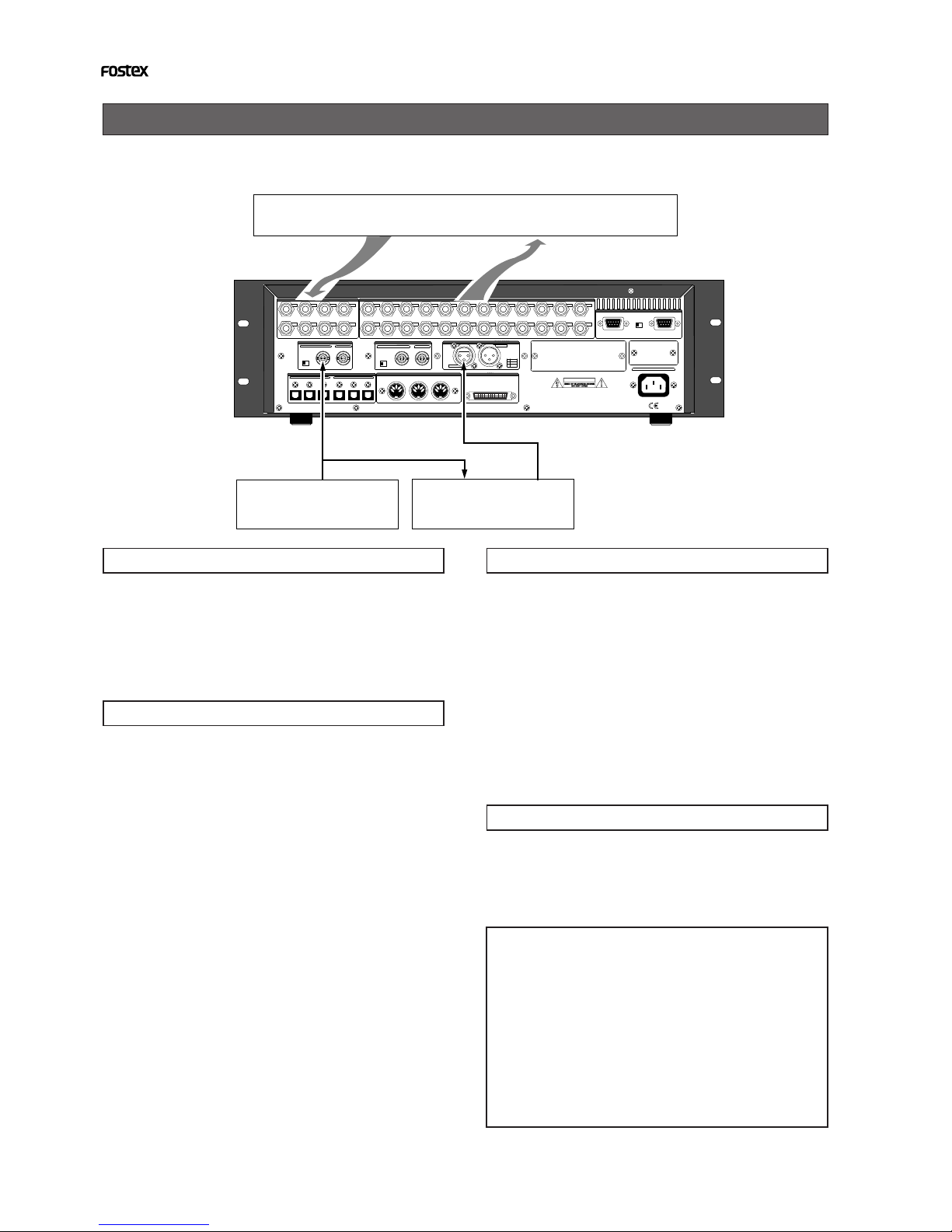
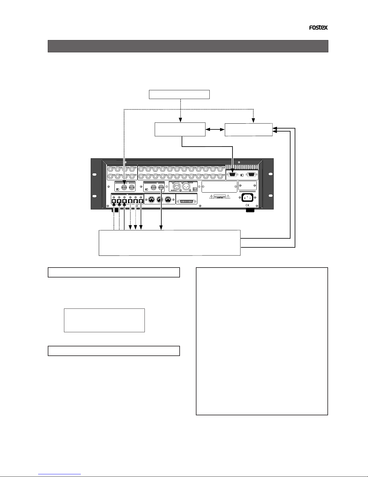
Chase sync to external timecode
The recorder with the Model 8345 installed can synchronize to incoming LTC by receiving the
external LTC via the recorder's TIME CODE INPUT terminal and setting the recorder's slave mode to
On.
<CAUTION>
• The recorder can chase incoming time code within
the range of continuously recorded time code.
If there is a discontinuity in the recorded time code,
when incoming time code runs across the discontinu-
ous point, “Out of Zone!” will appear in the display
and the recorder may stop chasing. If the time code
corresponding to the incoming time code is recorded
in a different area, play the recorder to that area.
• You can locate the recorder to the beginning of a
discontinuous time code by pressing the [NEXT] or
[PREV] key while holding down the [SHIFT] key.
Connection
In this example, the recorder with the 8345 is a slave
while the VTR is a master. Feed the time code from
the VTR to the TIME CODE INPUT terminal of the
recorder with the Model 8345 to play the recorder
in sync with the VTR. Also feed the video reference
signal to both the VTR and recorder as shown above.
Recorder settings
1. Select the program to be played back.
2. Set the reference time code to “LTC” by using the
“Ref. TC?” menu of the Setup mode.
3. Set the recorder's frame rate to the same rate as
the incoming time code by the “Frame Rate ?”
menu of the Setup mode.
The “Frame Rate?” menu of the Setup mode allows you
to select the desired frame rate from 24, 25, 29nd, 29df,
30nd and 30df.
4. Set the slave mode to ON by pressing the
[EXECUTE/YES] key while holding down the
[SHIFT] key.
5. Set the desired offset value by the “MTC OFFSET?”
menu of the Setup mode.
By setting the desired offset value, the recorder will run
with the offset between the VTR and recorder.
After all settings above are completed, press [EXIT/
NO] key (or the [STOP] button) to exit the Setup
mode.
Time code display
You can monitor the incoming timecode in the
D2424 display window.
1. Press the [DISP SEL] key while holding down the
[SHIFT] key to select “MTC”.
The display will show the current MTC offset value (the
default setting is "00h59m57s00f").
2. While “MTC” is selected, press the DISP SEL key
to select the timecode display.
When the recorder is receiving LTC, the display shows
the incoming LTC while “TC IN” lights in the display.
Synchronization with the VTR
1. Start playback of the VTR.
If an offset value is set, the recorder will start playback,
chasing the timecode from the VTR with maintaining
the offset.
75Ω
WORD
OUTPUTINPUT
OUTPUT
DATA
16 - 9
24 - 17 8 - 1
100Ω
RS422
THRU
AC-IN
INPUT
16 - 9
24 - 17 8 - 1
SCSI
ON OFF
REMOTE
MIDI
INPUT THRU
OUTPUT
1
2
34
5678
1
234
13141516
5
6
7
8
1718
19
20
9
10
11
12
21
22
2324
NE PAS OUVRIR
CAUTION
AVIS:
RISQUE DE CHOC ELECTRIQUE
WARNING:
TO REDUCE THE RISK OF FIRE OR ELECTRIC
SHOCK, DO NOT EXPOSE THIS EQUIPMENT
TO RAIN OR MOISTURE.
ANALOG INPUT BALANCE [ +4dBu ] / UNBALANCE [ -10dBv ] ANALOG OUTPUT BALANCE [ +4dBu ] / UNBALANCE [ -10dBv ]
ON OFF
INPUT
OUTPUT
HOT
GND
COLD
1
2
3
TIME CODE
THRUINPUT
ON OFF
75Ω
DATA MIDI
WORD
SCSI
REMOTE
ANALOG OUTPUT BALANCE [ +4dBu ] / UNBALANCE [ -10dBV ]
ANALOG INPUT BALANCE [ +4dBu ] / UNBALANCE [ -10dBV ]
VIDEO TIME CODE
Analog Mixer
HOUSE SYNC
TC
VIDEO SYNC
Audio Signal
Audio Signal
VTR
VIDEO SYNC

11
APPENDIX (Operation manual for the recorder with the Model 8345 TC/SYNC card installed)
Synchronization to word clock or video signal
The recorder with the Model 8345 installed can synchronize to an external sync signal such as word
clock and video composite signal.
Connection
<CAUTION>
If you use word clock as the reference clock, the sam-
pling frequencies of the external device and the re-
corder must match.
Because the sampling frequency of the recorder is set
when formatting the disk, make sure of the sampling
frequency of the external device before you start work-
ing.
Connection to a digital mixing console
The recorder with the Model 8345 installed can connect to a digital mixing console and record an
adat digital signal from the console.
In this example, the recorder receives external LTC from a VTR, etc., locks to the timecode, and
returns the locking information to the digital mixing console via the digital mixer. In this process,
the digital console outputs the adat digital signal to the recorder with the timing in sync with the
receiving word clock.
See the connection example on the next page.
In this example, according to the external device,
feed video or word sync signal to the WORD INPUT
or VIDEO INPUT terminal of the recorder.
Recorder's settings
1. Select the program to be played back.
2. Set the reference clock to “Word” or “Video”
according to the incoming sync signal by using
the “Clock Sel?” menu of the Setup mode.
75Ω
WORD OUTPUTINPUT
OUTPUT
DATA
16 - 9
24 - 17 8 - 1
100Ω
RS422 THRU
AC-IN
INPUT
16 - 9
24 - 17 8 - 1
SCSI
ON OFF
REMOTE
MIDI
INPUT THRU
OUTPUT
1
2
34
5678
1
234
13141516
5
6
7
8
1718
19
20
9
10
11
12
21
22
2324
NE PAS OUVRIR
CAUTION
AVIS: RISQUE DE CHOC ELECTRIQUE
WARNING:
TO REDUCE THE RISK OF FIRE OR ELECTRIC
SHOCK, DO NOT EXPOSE THIS EQUIPMENT
TO RAIN OR MOISTURE.
ANALOG INPUT BALANCE [ +4dBu ] / UNBALANCE [ -10dBv ] ANALOG OUTPUT BALANCE [ +4dBu ] / UNBALANCE [ -10dBv ]
ON OFF
INPUT
OUTPUT
HOT
GND
COLD
1
2
3
TIME CODE
THRUINPUT
ON OFF
75Ω
DATA MIDI
WORD
SCSI
REMOTE
ANALOG OUTPUT BALANCE [ +4dBu ] / UNBALANCE [ -10dBV ]
ANALOG INPUT BALANCE [ +4dBu ] / UNBALANCE [ -10dBV ]
VIDEO TIME CODE
Analog Mixer
External Device
WORD SYNC
VIDEO SYNC
Audio Signal
Audio Signal
12
APPENDIX (Operation manual for the recorder with the Model 8345 TC/SYNC card installed)
Recorder's settings
1. Set the preset to “Int. Vari adat” by using the
“Sync Preset?” menu of the Setup mode.
By selecting “Int. Vari adat”, the recorder is set as follows.
digital signal -> adat: Async
reference clock -> Int (internal)
slave type -> Vari
2. Set the reference time code to “LTC” by using the
“Ref TC?” menu of the Setup mode.
Digital mixing console's settings
1. Set the clock source of the digital mixing console
to “WORD” and the input to “Adat”.
Q
FREQ
GAIN
Q
FREQ
GAIN
Q
FREQ
GAIN
+10
0
-10
-20
-30
-40
-
+10
0
-10
-20
-30
-40
-
+10
0
-10
-20
-30
-40
-
+10
0
-10
-20
-30
-40
-
+10
0
-10
-20
-30
-40
-
+10
0
-10
-20
-30
-40
-
+10
0
-10
-20
-30
-40
-
16
PAN
Q
PAN
ON ON ON ON ON ON ON
SOLO SOLO SOLO SOLO SOLO SOLO SOLO
EQ EDIT EQ EDIT EQEDIT EQ EDIT EQ EDIT EQ EDIT EQ EDIT EQ EDIT
SOLO
ON ON
SOLO
STORERECALL
EQ ON
STORERECALL
STORERECALL
SOLO
+1/
/-1
DATA
EXIT
ENTER
MASTER
15
1413
1211
10
9
1-8 ANALOG IN 9-16 ADATIN 17-20 EFF RTN
AUX1 AUX2
AUX3 AUX4
EFF1 EFF2
ADD.AUX
+10
0
-10
-20
-30
-40
-
ADAT IN
0
-10
-20
-30
-60
-
-40
PANPANPANPA NPA NPA N
-40
-36
-24
-18
-12
-9
-6
-3
OL
ST BUSS/SOLO
LR
METER
CHANNEL
FADER MODE
KEY MODE
METER
CHANNEL/
CHVIEW
PHASE GROUP
ROUTING/ PAIR/
MMC SEND
CURRENT SCENE STATUS
SETUP
SYSTEM MIDI
EQ/LO EQ/LO-MID EQ/HI-MID EQ/HI-MID
FREQ
GAIN
EFF EDIT
EFF 2EFF 1
EQ LIBRARY EFF LIBRARY
SELECTED EQ
SCENE MEMORY
REC BUSS
8
7
6
5
4
2020
1 2 3
1919
1818
1717
ANALOG INANALOG IN
EFF REFF RTNTN
PAGESELECT
VTR
75Ω
WORD
OUTPUTINPUT
OUTPUT
DATA
16 - 9
24 - 17 8 - 1
100Ω
RS422 THRU
AC-IN
INPUT
16 - 9
24 - 17 8 - 1
SCSI
ON OFF
REMOTE
MIDI
INPUT THRU
OUTPUT
1
2
34
5678
1
234
13141516
5
6
7
8
1718
19
20
9
10
11
12
21
22
2324
NE PASOUVRIR
CAUTION
AVIS: RISQUE DE CHOC ELECTRIQUE
WARNING:
TO REDUCE THE RISK OF FIRE OR ELECTRIC
SHOCK, DO NOT EXPOSE THIS EQUIPMENT
TO RAIN OR MOISTURE.
ANALOG INPUT BALANCE [ +4dBu ] / UNBALANCE [ -10dBv ] ANALOG OUTPUT BALANCE [ +4dBu ] / UNBALANCE [ -10dBv ]
ON OFF
INPUT
OUTPUT
HOT
GND
COLD
1
2
3
TIME CODE
THRUINPUT
ON OFF
75Ω
DATA MIDI
WORD
SCSI
REMOTE
ANALOG OUTPUT BALANCE [ +4dBu ] / UNBALANCE [ -10dBV ]
ANALOG INPUT BALANCE [ +4dBu ] / UNBALANCE [ -10dBV ]
VIDEO TIME CODE
13
APPENDIX (Operation manual for the recorder with the Model 8345 TC/SYNC card installed)
Control from a video editor (RS-422)
The recorder with the Model 8345 installed can be used for audio editing for video using a video
editor. Connect a video editor to the recorder's REMOTE IN (RS-422) terminal, as well as connect a
video sync signal to the recorder, video editor and VTR as the reference signal. With this connec-
tion example, you can edit audio for video by controlling the VTR and recorder from the video
editor.
Recorder's settings
1. Set the preset to “Video Free adat” by using the
“Sync Preset?” menu of the Setup mode.
By selecting “Video Free adat”, the recorder is set as
follows.
digital signal -> adat: Async
reference clock -> Video
slave type -> Free
Digital mixing console's settings
1. Set the reference clock of the digital mixing
console to “WORD”.
<CAUTION>
Most popular video editors can be used with the re-
corder/8345, however, we cannot guarantee that all
video editors can be used or all functions work cor-
rectly (also note that the recorder/8345 does not sup-
port audio editors). We recommend to check whether
functions work correctly or inquire to the manufac-
turer/dealer of an editor before using/purchasing.
Also refer to the "Basic parameter settings for edi-
tors" below when using an editor.
<Basic parameter settings for editor>
We recommend to set editor parameters as shown
below when controlling the recorder. Note that these
settings are just for reference and we cannot guaran-
tee all functions work correctly with the settings.
* Preroll time: more than 5 seconds
* Edit delay: 0 frame
* EE delay: 0 frame
* Over run: 0 frame
* Trajectory: "Cue with Data command" is recommended
* Start delay: 0 frame (depending on editors)
75Ω
WORD
OUTPUTINPUT
OUTPUT
DATA
16 - 9
24 - 17 8 - 1
100Ω
RS422
THRU
AC-IN
INPUT
16 - 9
24 - 17 8 - 1
SCSI
ON OFF
REMOTE
MIDI
INPUT THRU
OUTPUT
1
2
34
5678
1
234
13141516
5
6
7
8
1718
19
20
9
10
11
12
21
22
2324
NE PAS OUVRIR
CAUTION
AVIS:
RISQUE DE CHOC ELECTRIQUE
WARNING:
TO REDUCE THE RISK OF FIRE OR ELECTRIC
SHOCK, DO NOT EXPOSE THIS EQUIPMENT
TO RAIN OR MOISTURE.
ANALOG INPUT BALANCE [ +4dBu ] / UNBALANCE [ -10dBv ] ANALOG OUTPUT BALANCE [ +4dBu ] / UNBALANCE [ -10dBv ]
ON OFF
INPUT
OUTPUT
HOT
GND
COLD
1
2
3
TIME CODE
THRUINPUT
ON OFF
75Ω
DATA MIDI
WORD
SCSI
REMOTE
ANALOG OUTPUT BALANCE [ +4dBu ] / UNBALANCE [ -10dBV ]
ANALOG INPUT BALANCE [ +4dBu ] / UNBALANCE [ -10dBV ]
VIDEO TIME CODE
Digital Mixer
Video Editor VTR
HOUSE SYNC
VIDEO SYNC VIDEO SYNC
AUDIO
WORD
VIDEO SYNC
adat
adat
Table of contents
Other Fostex Recording Equipment manuals


Popular Recording Equipment manuals by other brands
iCON Pro Audio
iCON Pro Audio Upod Pro user manual

Extron electronics
Extron electronics RGB 109xi Setup guide

Command access
Command access PM300ACD installation instructions

Helmer
Helmer i.C3 user guide

Allen-Bradley
Allen-Bradley DeviceNet CompactPCI 1784-CPCIDS installation instructions

Laserworld
Laserworld Net OEM user manual


TE Connectivity
TE Connectivity FPX Series installation instructions

Philips
Philips CDR950BK99 Instructions for use

Pepperl+Fuchs
Pepperl+Fuchs IC-KP-R2-V1 manual

Miditech
Miditech MIDI controller keyboard owner's manual

HDT
HDT HDSSFG20B instruction manual

GE Interlogix
GE Interlogix NetworX NX-2192E-EUR installation manual