Nautilus HYDRO-FORCE MX3-500HE User manual

1
LMANN18 REVISED: 02-16-2018
MX3
-
500H
E
Nautilus
Ope ating Manual

2
Nautilus MX3-500HE Operating Manual
TABLE OF CONTENTS
TOPIC PA E #
•Introduction 3
•Technical Specifications 4
•Optional Equipment 5
SECTION 1: Operational Safety
•Electrical Safety 6
•Mechanical Safety 7
SECTION 2: Operation Procedures
•Vacuum Connections 8
•Electrical Supply 9
•Water Supply & Chemicals 10
•Solution Hose & Pump Priming 13
•Heater & Vacuum Hose 14
•Foam Downer 15
•Pump-Out System 16
•Pressure Adjustments 17
•Shutdown Procedures 18
•Accessory Storage 19
•Troubleshooting 20
•Solution Flow Path 23
•Wiring Diagrams 24
SECTION 3: Maintenance/ Technical
•Maintenance 27
•Drawings & Parts Lists
oPump 36
oPressure Regulator 37
oAuto-Fill 38
oPump-Out Pump 40
oParts Pictures 41
oParts List 53
oHose List 56
•Warranty 57

3
Introduction
Cong atulations on you pu chase of the Hyd o-Fo ce Nautilus MX3-500HE. The
MX3-500HE is designed to give t uckmount-level pe fo mance in a po table
machine that combines ve satility with ease of t anspo t. Yea s of expe ience,
enginee ing, and planning have gone into the design and manufactu ing of the
MX3-500HE. We take a g eat deal of p ide in the MX3-500HE; ou goal is no less
than you complete satisfaction.
This manual will p ovide use s with the knowledge equi ed to ope ate the
Nautilus MX3-500HE safely, to unde stand how to p ope ly ope ate and maintain
the machine, and to ensu e that the equipment ope ates at its maximum
pe fo mance level.
All users must read and understand this manual completely before
operating the machine.
Always maintain this manual in legible condition adjacent to the Nautilus MX3-
500HE, o place in a secu e location fo futu e efe ence.
Any questions pe taining to the ope ating o se vicing of this unit should be
di ected to you nea est Hyd o-Fo ce dist ibuto .
This manual is w itten specifically fo the Nautilus MX3-500HE po table
ext acto units manufactu ed by:
Hyd o-Fo ce
4282 South 590 West
Salt Lake City, UT 84123
801-268-2673
801-268-3856 FAX
Info mation in this manual is subject to change without notice and does not
ep esent a commitment on the pa t of Hyd o-Fo ce o its pa ent o affiliated
companies.

4
Technical Specifications
MX3-500HE High Pressure Extractor
Height: 42-1/4” (107.32cm)
Length: 34-3/8” (87.31cm)
Width: 23-3/8” (59.37cm)
Weight: 144 lbs. (65.23kg.)
Solution Tank Capacity: 12 gallon (45.4 Liters)
Recovery Tank Capacity: 12 gallon (45.4 Liters)
Solution Pump: Pump-Tec #207 pump with 1/2 HP Motor - 0-500 psi
1.06 gpm / 4.01lpm
220V 50Hz – 3.4amps / 230V 60Hz – 2.8amps
Vacuum Motors: Two AMETEK Lamb 5.7” diameter 3-Stage – tangential discharge
Can be operated in series or parallel configuration
Pump-out Pump: FloJet 230VAC 5.0 gpm (0.75amp)
(Optional)
Power Draw: Cord #1 –10.42Amps wide open / 6.72Amps full load
Cord #2 – 10.04Amps wide open / 8.69Amps full load
(Add 0.75amp to Cord #2 for units with optional Pump-Out Pump)
Standard Equipment
Vacuum Connection: 2” Barb or 2”Male Flash Cuff with 2” Male NPT
Vacuum Hose: 25’ X 1-1/2” with 1-1/2” cuff & 2” cuff
2” Female Flash Cuff x 1-1/2” hose adapter
Carpet Wand:
1-1/2” SS Dual Jet S-Bend Wand
– AW29
Accessory Mounting Hardware: Four 1/4-20 x 5/8” SS Screw s and Washers
HP Solution Hose: 25’ x 1/4” with 1/4” male & female quick connects
Pump Priming Hose: 12” x 1/4” with 1/4” male quick connect
Power Cords: 2 – 15M Extension Leads with male & female plug ends
Electrical: 1750W Heater
5amp Pump Circuit Breaker
Internal Component Cooling Fan
Optional Features:
Auto Fill System with chemical draw:
Metering Tip Kit: 14 different tips for changing chemical dilution rate
Water Supply Hose: 50’ x 3/8” with 1/4” female quick connect &
Female garden hose fitting
Auto Pump-out System:
Pump-out Hose: 50’ x 3/4” with male & female garden hose fittings

5
Additional / Optional Equipment
Wand lide – Delrin AW529D
Wand lide – Teflon AW529T
18” Bottom Velcro Strap for Wand Holder NM5841
Hy-Dry Deluxe Upholstery Tool: AW50D
Flash Xtractor II: AC002
ekko Handle Assembly: AR51A
ekko 4” Tool Head: AR51D
SX-7 Tool Head: AR51
ekko Hand Tool: AR53
1-1/2” Vacuum Hose: (Sold per foot – No cuffs) AH36
2” cuff for 1-1/2” Vac Hose: AH46
1-1/2” cuff for 1-1/2” Vac Hose: AH42
1-1/2” Hose Connector PVC: AH74
HP Solution Hose 1/4” X 25’ w/M-F Quick Connects AH79D
1/4” Male Quick Connect: AH102B
1/4” Female Quick Connect: AH101B
Pump-out Hose: AH65
Hydro Filter II: AC10
Replacement Screen for Hydro-Filter II: AC10C
Metering Tip Kit: PDE001
Belt Pack AX108
AC10
AX108
AR51A
AW50
AR51G
AR51
AR53
AC002

6
Safety
This machine is an electrical appliance.
Care must be taken to reduce the risk of electrical shock.
•READ AND UNDERSTAND ALL INSTRUCTIONS BEFORE OPERATIN THE MX3-500HE.
•To educe the isk of p ope ty damage o inju y, epai s to elect ical systems should only be pe fo med by
expe ienced technicians. Contact you dist ibuto fo assistance. Unplug machine powe co d f om outlet
befo e pe fo ming any epai s on the ext acto .
•This machine shall be g ounded while in use to p otect the ope ato f om elect ic shock. The machine is
p ovided with a th ee-conducto co d and a th ee-contact g ounding type attachment plug to fit the
p ope g ounding type eceptacle. The g een and yellow conducto in the co d is the g ounding wi e.
Neve connect this wi e to othe than the g ounding pin of the attachment plug.
•This machine is fo use on a nominal 240-volt ci cuit and
has a g ounding plug that esembles the plug illust ated in
the sketch to the ight. Make su e that the machine is
connected to an outlet having the same configu ation as
the plug. No plug adapte should be used with this
machine.
• The powe co ds supplied with this machine a e p ope ly
sized to handle the elect ical load of this machine and
p ope ly g ounded as desc ibed above. Any extension
co ds used with this machine must be simila ly sized with
an equal o g eate load ating and g ounded to assu e
safe ope ation.
•The two powe co ds must be plugged into sepa ate ci cuits du ing ope ation.
•Do not use the MX3-500HE outdoo s, in standing wate o on wet su faces. Do not sto e the MX3-500HE in
wet conditions. If ext acto is leaking, unplug machine powe co ds f om outlets befo e app oaching o
touching machine.
•Do not unplug powe co d by pulling on the co d. G asp the plug end when unplugging the co d. Do not pull
the ext acto by the co d. If co d o plug is damaged, do not use co d. Replace with new co d o epai as
needed befo e use.
•Ove loaded ci cuit may not always t ip ci cuit b eake . Reduced voltage to a machine on an ove loaded ci cuit
will p event components f om ope ating p ope ly.
Section
1
OUTLET

7
This machine must be protected from conditions which
may damage the pump, tank, hoses and other components.
•Freezing of water in this machine will cause serious damage. The Nautilus MX3-500HE, solution hoses,
and tools must be p otected f om f eezing tempe atu e. Sto e, t anspo t, and use this equipment only in
tempe atu es well above f eezing. (32ºF o 0ºC). If you suspect the Nautilus MX3-500HE has been f ozen, do
not plug in o tu n on machine until you a e su e it has thawed completely.
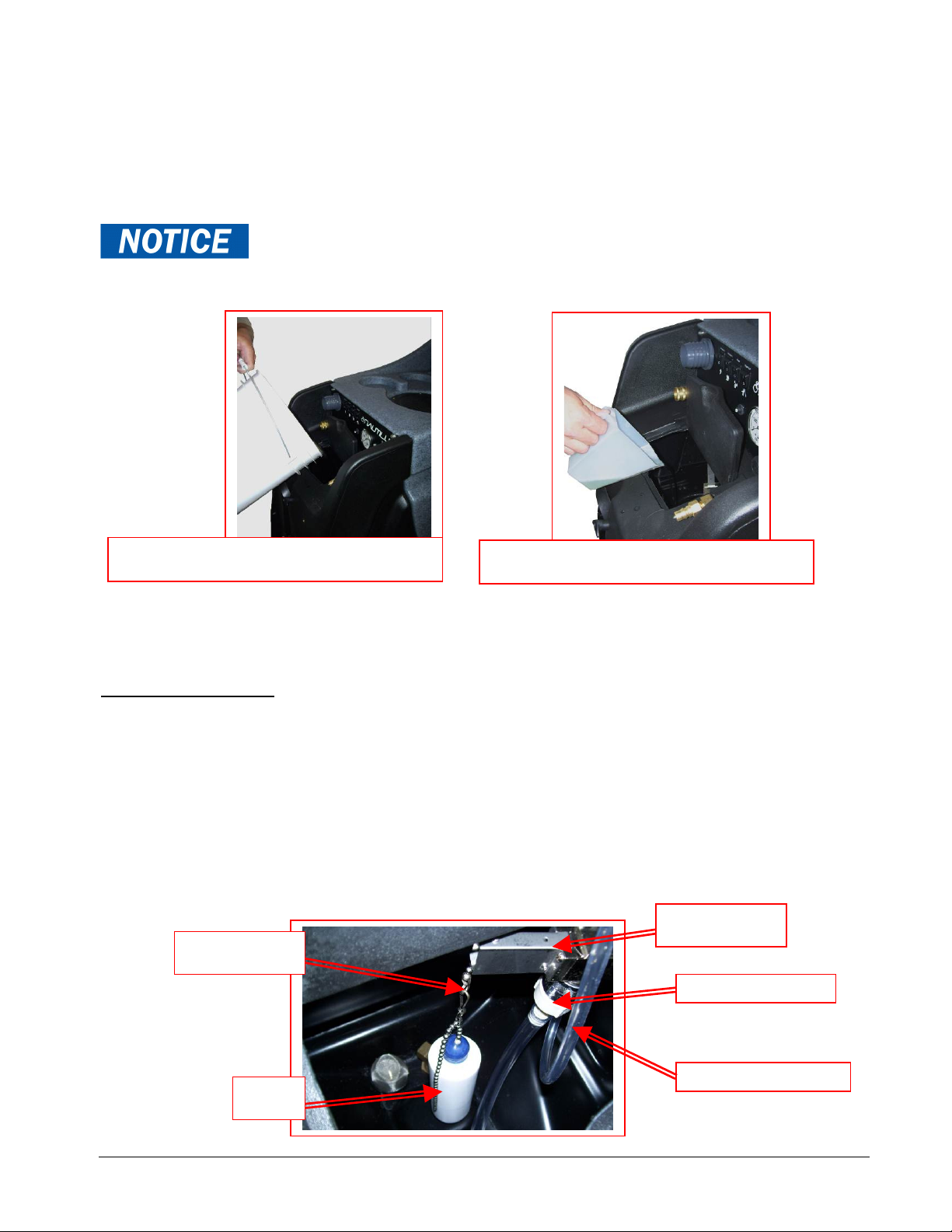
•If the equipment cannot be sto ed o t anspo ted in a wa m envi onment, it can be gua ded f om f eezing by
unning an anti-f eeze solution th ough the incoming wate lines, chemical feed system, solution pump, solution
lines, tools and pump-out pump. The machine is filled at the facto y with anti-f eeze to eliminate damage du ing
shipment in cold weathe .
oThe anti-f eeze solution must be completely flushed f om the machine befo e it is etu ned to se vice.
•The MX3-500HE must not be used to pick up flammable o combustible mate ials o used in a eas whe e these
mate ials may be p esent.
•Solvent-based o wate -based solutions containing solvents may damage the pump, hoses, and othe
components. Do not assume chemical compatibility. Contact you dist ibuto o Hyd o-Fo ce if you have
questions ega ding the compatibility of you chemicals with the machine.
•Do not clean with solutions that a e at tempe atu es above 130ºF o 54ºC.
•Rinse the solution tank, chemical system, and pump with f esh wate afte each day’s use.
•Do not allow pump to un d y. Always maintain adequate solution level to supply solution pump.
•HP hoses may uptu e if wo n o damaged. Do not use HP solution hoses if hose cove ing is cut, bulging, o
othe wise damaged. Examine HP solution hoses daily and eplace o epai hoses as needed.
•Use a Hyd o-Filte II and clean the ecove y tank daily to keep pump-out filte and pump f om becoming
clogged. Sto e the Nautilus MX3-500HE with the ecove y tank lid open.
•Keep Vacuum Inlet Filte clean and check float fo p ope ope ation. Do not ope ate the Nautilus MX3-
500HE without the Vacuum Inlet Filte in place. Use defoamer to eliminate foam build-up during
cleaning and prevent foam/moisture from entering vacuums.
Use common sense to protect yourself and others while using this equipment.
•Keep pets and child en away f om the machine when in use.
•Keep all body pa ts, hai , and loose clothing away f om openings and moving pa ts. Always wea app op iate
wo k clothing and safety equipment when ope ating unit.
•Use ext a ca e when cleaning on stai s. Wet ca pet on stai s can be slippe y.
•Do not move the MX500H up o down stai s when tanks a e full of wate . D ain solution and ecove y tanks,
and secu e base latches befo e moving unit up o down stai s. Lift using only the machine handles designed &
designated fo moving and lifting.
•Wate may be spilled, d ip, o be exhausted f om vacuums du ing ope ation. Place unit in a ea whe e wate will
not cause damage o use d op cloth to p otect su faces.

8
Vacuum Connections
The MX3-500HE has a unique vacuum system which allows you to
connect your vacuums in either parallel or in series. Vacuum
connections can be changed quickly, with only a screw driver.
∗THIS MUST BE PERFORMED BY A QUALIFIED
TECHNICIAN
While there is debate on which vacuum alignment provides the best
extraction, this much is true:
•Two vacuums in series: The vacuum lift is increased by 1.6 times
the rating of a single vacuum, while the air flow stays the same as
a single vacuum.
•Two vacuums in parallel: The vacuum air flow is increased by 2.0
times the rating of a single vacuum, while the lift says the same.
Air flow is usually measured in cubic feet per minute, indicated as CFM.
Lift is usually measured in inches of water column, indicated as “H2O or “WC.
To connect vacuums in parallel:
1. Connect the discha ge / exhaust hose f om vacuum #1 to the
exhaust pipe on machine base.
2. Place the ubbe stoppe into the vacuum inlet po t of vacuum
manifold numbe two.
3. Open vacuum gate valve and attach the Gatekeepe to p event
accidental valve closu e.
When connected in pa allel, both vacuums must be unning du ing
cleaning. Vacuums cannot be ope ated individually.
To connect vacuums in series:
1. Connect the discha ge / exhaust hose f om vacuum #1 to the
vacuum inlet po t of vacuum manifold numbe two.
2. Place ubbe stoppe into the exhaust pipe on machine base.
3. Remove Gatekeepe and close vacuum gate valve.
When connected in se ies vacuums can be ope ated individually if desi ed du ing cleaning.
Always secure the Gate Valve Open with the
Gatekeeper when connecting the vacuums in Parallel. Closing
the Vacuum Gate Valve with the hoses connected in the
Parallel configuration may cause damage to Vacuum
#2.
Section
2
GATEKEEPER

9
Operation Procedures
Knowledge of the proper operation of the MX3-500HE is required to
ensure user safety and efficient performance of the extractor.
SET UP AND OPERATION
1. Electrical Cords:
Two 15M Extension co ds a e supplied with the Nautilus MX3-500HE. The ampe age equi ed by each co d
equi es that the two co ds be plugged into sepa ate ci cuits:
•Co d #1 (Left side) Powe s vacuum #1, vacuum #2 and cooling fan.
•Co d #2 (Right side) Powe s solution pump and the 1750W heate and APO if so equipped.
Both co ds must be connected to sepa ate 220/230 volt 10amp ci cuits. An ove loaded ci cuit will not always
t ip the ci cuit b eake immediately, but may not p ovide sufficient voltage fo p ope ope ation and the
b eake may t ip eventually.
Plug the powe co ds into two sepa ate outlets with sufficient voltage and an amp ating fo the powe
demands of the MX3-500HE, connect the co ds to the MX3-500HE and then p oceed with you set-up.
If a ci cuit b eake t ips o the pump ci cuit b eake t ips du ing ope ation, eset the b eake s and move the
co d to anothe outlet as needed.
When operating the MX3-500HE using the 1750W heater DO
NOT turn the heater on until after the pump has been primed and solution hose and
tool connected – Steps #3, #4 & #5.
Cord #1 Cord #2
EXTENSION CORD:
#CSRCE1515
15M – 1.5M2 3-GAUGE
M-F PLUGS

10
2A. Water Supply & Chemical Mixing– Manual Fill:
•Pou up to 12 gallons (45.4 Liters) of hot wate into the solution tank at the f ont of the machine. The
water temperature cannot exceed 130°
°°
°F or 54°C.
•Measu e and add the app op iate amount of the desi ed liquid chemical to the wate in the solution tank.
The amount of chemical will va y depending on the type of chemical used, the amount of wate in the
tank, and the mate ial being cleaned; consult the chemical packaging fo specific mixtu e atios.
•Powde ed chemicals should be dissolved in wate befo e adding to the wate in the solution tank.
DO NOT RUN OUT OF WATER WHILE USIN THE MACHINE! Ensure
that the tank contains enough water to complete each job. If the water level is low: stop cleaning,
turn off the pump, and refill the tank. Running the pump dry will damage the pump and void the
warranty.
2B. Optional Auto-Fill System - Water Supply & Chemical Dilution:
•The chemical dilution ate is cont olled by the mete ing tip, and the dilution ate can only be changed by
changing the mete ing tip (See “How to Change the Mete ing Tip” on Page 11 fo inst uctions.)
Chemical Feed Setup:
•Remove the chemical feed hose f om the solution tank. Make su e float is attached to valve and hanging
f eely, above the bottom of the solution tank. Adjust float height to maintain adequate wate level.
•Place the end of the chemical feed hose into a containe of liquid chemical.
•If the tip is emoved, and the p opo tioning system ope ated with no tip, the dilution ate will be 8:1, the
equivalent to adding 16-1/4oz of chemical to each gallon of wate . (125 ml pe lite of wate )
•The ecommended tip fo use with the MX3-500HE is the tu quoise tip with a dilution ate of 256:1. This
means that fo each gallon of wate flowing into the machine, 1/2 ounce of chemical will be added.
(3.91ml of chemical pe lite of wate )
If a fresh water rinse with no chemical is desired, simply leave the chemical feed hose inside the
solution tank.
Proportioning Valve
Chemical Feed Hose
Float Hanger
Float
Pour appropriate amount of hot water into
solution tank
Add appropriate amount of chemical to water
in solution tank
Float Valve

11
How to Change the Metering Tip:
•Remove the chemical feed hose f om the ba b on the side of the p opo tioning valve.
•Unsc ew and emove the old tip.
•Sc ew in the p ope tip fo you chemical tip and place the hose back on the ba b
Metering Tip Kit (Hydro-Force Item# PDE001) contains 14 diffe ent colo ed mete ing tips, allowing
dilution ates f om 11:1 up to 427:1. Refe to the cha t below to select the tip that meets the dilution ate fo
you chemical application.
•Fo example: if you equi e 1-1/2 ounces of chemical pe gallon of wate , change to the ed mete ing tip
with the dilution ate of 85:1. (11.77ml of chemical pe lite of wate )
•The dilution ates a e based on chemicals with wate -like viscosity. Thicke (mo e viscous) chemicals will
dilute at a diffe ent ate.
•Fo powde ed chemicals, a liquid concent ate must be made. Mix the concent ate acco ding to the
manufactu e ’s di ections, and then select the app op iate mete ing tip.
•Contact you dist ibuto o Hyd o-Fo ce if you have questions about you chemical.
Metering Tip Application Chart:
Metering Tip Kit – PDE001
Turquoise Tip
Dilution 256 - 1
Red Tip
Dilution 85 - 1
Proportioning Valve
Chemical Feed Hose
TIP
COLOR
CHEMICAL DILUTION
RATES
OZ / GAL (RATIO)
RATES
ml / lite
TAN 0.30 (427:1) 2.34
ORANGE 0.40 (320:1) 3.13
TURQUOISE 0.50 (256:1) 3.91
PINK 0.75 (170:1) 5.88
LIGHT BLUE 1.00 (128:1) 7.81
BROWN 1.12 (114:1) 8.77
RED 1.50 (85:1) 11.77
WHITE 1.75 (73:1) 13.70
GREEN 2.00 (64:1) 15.63
BLUE 2.50 (51:1) 19.60
YELLOW 3.75 (34:1) 29.41
BLACK 5.00 (26:1) 38.46
PURPLE 8.50 (15:1) 66.67
GRAY 11.50 (11:1) 90.90
NO TIP 16.25 (8:1) 125.00

12
Water Supply:
•Once the co ect mete ing tip is in place:
oConnect the Auto-Fill Wate Supply Hose to the wate inlet (the male quick-connect on the f ont
of the machine.)
oConnect the othe end of the hose to a wate faucet, and then tu n on the wate .
•Hot wate can be used as long as the tempe atu e does not exceed 130°F o 54°C.
•Faucet adapte kits (Hyd o-Fo ce item #AX21 & AX22) a e available that allow connection to diffe ent
types of faucets if needed.
To adjust the water level in the solution tank:
•Tu n off the wate supply.
•Adjust the length of the chain connecting the float bottle to
the float valve. Unhook the float f om the beaded chain on
the valve. Unsnap the hook f om the beaded chain on the
float.
Move the bottle down to dec ease the wate level.
Move the bottle up to inc ease the wate level.
•Snap the back onto the float chain & hook the float back
onto the valve chain.
•Tu n the wate supply back on.
If the chemical is not d awing, o if the tank is not filling
o is ove flowing, efe to the t ouble shooting guide, o
contact you dist ibuto fo assistance.
Connect the Auto-Fill Water Supply Hose to Solution Inlet
(Male quick connect on the front of the machine.)
3/8” id X 25’ with F Quick Connect & F Garden Hose Fitting
Float Valve
Float Bottle
Connect the Auto-Fill Water Supply Hose to a
faucet and turn on the water
Chemical
Feed Hose
Float Hanger Hook

13
3. Priming the High-Pressure Pump:
Once wate is in the solution tank, the high p essu e pump must be p imed:
•The e is a p iming hose included with the machine. Connect the p iming hose to the solution outlet –
female quick connect on the f ont of the machine.
•Tu n on both vacuums and the solution pump. Inse t the end of the p iming hose into the vacuum
inlet po t on the f ont of the machine and cup you hand a ound the hose to block off the vacuum
inlet with you hand. The vacuum will pull solution th ough the pump and p iming hose into the
vacuum tank.
•Tu n off the pump and then the vacuums. Disconnect the p iming hose. You can now continue you
set-up. As long as the e is solution in the tank, the pump should emain p imed.
If the pump still does not p ime, o if flow is low o unsteady, check the hose f om the solution tank to the
pump (as well as the filte ) fo clogging, kinks, o est ictions. Clean o eplace hose and/o filte and epeat
the p iming p ocedu e.
If you a e having t ouble with the pump, efe to the t ouble shooting guide o contact you dist ibuto fo
advice o assistance.
4. Connection of Solution Hose:
Connect the high p essu e solution hose to the solution outlet (female quick connect on the f ont of the
machine). Connect the othe end of the hose to the male quick connect on the cleaning tool. When you a e
eady to sta t cleaning, tu n the solution pump switch to the ON position. The p essu e is p eset, the e is no
p essu e adjustment to be made.
Connect the male end of the HP Solution Hose
Assembly to the female solution outlet fitting on
the machine. Connect the female end to the
cleaning tool.
HP Solution Hose Assembly – AH79D
1/4” id X 25’ with M-F Quick Connects
PUMP PRIMING HOSE
NM5080

14
5. 1750W Heater Operation:
To prevent damage to the heater, the heater must have water in it before it is
turned ON. Fill solution tank, prime the pump and connect solution hoses before turning heater
ON.
While the heate allows fo maximum ope ating tempe atu e of app oximately 190ºF o 88°C, the
tempe atu e of the cleaning wate delive ed to the tool is dependent on two facto s:
•The sta ting tempe atu e of the wate : Sta ting with hotte wate will equi e a smalle tempe atu e
inc ease f om the heate to each the maximum tempe atu e.
The water temperature in the solution tank cannot exceed 130°
°°
°F or 54°C.
•Flow ate: The lowe the flow ate of the wate th ough the heate , the mo e time the wate will be inside
the heate . The wate will have mo e time to be heated and can each a highe tempe atu e. High wate
usage and flow ate will not allow the wate enough time to be heated and the tempe atu e of the wate
delive ed to the tool will be much lowe .
The flow ate can be lowe ed by putting smalle jets in the cleaning tool and by educing the amount of
time the wand is sp ayed. Taking additional d ying stokes without sp aying wate between sp aying
st okes will help inc ease the potential tempe atu e ise.
6. Connection of Vacuum Hoses:
The vacuum connection po t on the machine can be eithe
a 2” hose ba b o 2” male Flash Cuff. Both a e included
with you MX3-500HE. The desi ed connecto can be
th eaded into the vacuum po t on the f ont of the machine.
A 2” female Flash Cuff 1-1/2” hose adapte is also included
to connect the 1-1/2” vacuum hose to the 2” male Flash
Cuff on the machine.
A 2” hose cuff fo 1-1/2” vacuum hose is included to
connect the 1-1/2” vacuum hose to the 2” hose ba b on the
machine.
With the p ope cuff attached to the 25’ Vacuum Hose, the
25’ vacuum hose is then connected to the vacuum
connection po t on the MX3-500HE. The othe end with
the 1-1/2” cuff is connected to the cleaning tool.
When eady to begin cleaning, tu n both vacuum switches to
the ON position. If connected in se ies, the MX3-500HE
can be ope ated with only one vacuum fo cleaning delicate
fab ics. (See Vacuum Connection inst uctions on Page 8) In
most situations you will tu n both vacuum switches ON.
VACUUM CONNECTION WITH STANDARD
BARB AND VINYL CUFF
VACUUM CONNECTION WITH FLASH
CUFFS

15
7. Optional Foam Downer:
A key p oblem with po table ext acto s is that they have small tanks whe e foam dissipates slowly. If you
have had issues with foam o a e anticipating foaming p oblems, you will want to use a Foam Downe .
Foam can be d awn into the vacuums befo e the vacuum shutoff closes. Foam and wate blowing out the
vacuum makes a big mess, can dec ease vacuum lift and damage the vacuum moto s.
The Foam Downe kills foam as waste wate ente s the machine. Place a containe of liquid defoame on the
top of you MX3-500HE. The vacuum ai flow siphons the liquid defoame th ough Foam Downe into the
vacuum tank, b eaking down the foam befo e it can cause any damage o make a mess.
•Mounts and is eady to use in seconds
•Uses defoame ve y economically
•NO LABOR is involved to sp ay o sp ead defoame – it’s all automatic
•Keeps silicone defoame s off the floo whe e they can cause esoiling p oblems
The Foam Downe is an attachment that allows the vacuum to d aw a small amount of defoame in a
constant slow flow into the waste tank of the Nautilus. We ecommend using a diluted defoaming solution of
fou ounces of defoame to one gallon of wate (1-32) o 31.25ml pe lite . Place the d aw tube into the gallon
of diluted defoame and open the needle valve one half tu n as you sta ting point. If this is not sufficient to
b eak down the foam you can open the valve mo e o add mo e defoame to the wate to make a st onge
solution.
With the valve open one half tu n it will take app oximately one half hou to d ain the gallon of diluted
defoaming solution.
FOAM
DOWNER
AH17
FOAM DOWNER cannot be used
with 2” Male Flash Cuff connecto
on machine. Remove 2” Male Flash
Cuff and install 2” hose ba b as
needed.
HOSE HOOK
AH95

16
8. Connection of Optional Pump-Out Hose:
If you machine has the Optional Auto Pump-Out System you may want to connect the Pump-Out Hose.
The pump-out hose is a 50’ section of 3/4” ga den hose. (Use of smalle diamete hose may educe flow.)
•Remove the cap f om the pump-out outlet fitting on the back of the machine.
•Connect the pump-out hose to the outlet fitting.
•Place the othe end of the hose in a commode o d ain connected to the sanita y sewe system.
•Secu e hose end to p event movement du ing pumping.
Use defoamer to prevent foam build-up in recovery tank during cleaning and to keep
foam/moisture from entering vacuums.
Use Hydro Filter II inline filter to trap and remove debris from the waste water before it
enters the recovery tank. Excess debris in recovery tank may clog Pump-Out filter. Clean
Filter as needed during use.
Do not turn the Waste Pump switch ON unless pump-out hose is connected and has been
routed to a proper drain.
The Waste Pump does not use a float switch and will run as soon as the Waste Pump switch
is turned ON. It is made to run continuously while cleaning, as this type diaphragm pump
can run dry without damage.
When eady to begin cleaning, tu n the Waste Pump switch to the ON position.
If not using the waste pump-out, the pump-out hose does not need to be connected. When the ecove y tank
fills du ing cleaning, the float assembly in the vacuum inlet filte will ise and will automatically shut off the
vacuum ai flow to p event the ecove y tank f om ove filling and waste wate f om getting into the vacuums.
When this occu s:
•Immediately shut off the vacuum switches.
•D ain the ecove y tank.
oTu n off the pump switch while d aining the tank.
oTu n pump switch back upon esumption of cleaning.
•Close the d ain valve and tu n the vacuum switches back on when
eady to esume cleaning.
If the pump-out o vacuum shutoff is not wo king p ope ly, efe to the
t ouble shooting guide o contact you dist ibuto fo advice o assistance.
Connect the
Female Garden
Hose Fitting end
of the Pump-out
Hose to the outlet
fitting on the back
of the recovery
tank. Place the
other end of the
pump-out hose in
a sanitary drain.
Float Shutoff Assembly
D aining the Recove y Tank
Pump
-
out Filter

17
9. Pressure Adjustment:
To make it easie to check and adjust the p essu e, the p essu e gauge and the p essu e egulato a e mounted
on the cont ol panel on the f ont of the machine. When the high-p essu e solution pump is on and p imed,
p essu e will show on the gauge.
•To dec ease the p essu e, tu n the b ass knob on the p essu e egulato to the left (counte -
clockwise.)
•To inc ease the p essu e, tu n the b ass knob on the p essu e egulato to the ight (clockwise.)
•To adjust p essu e to you tool and su face equi ements:
oCheck the p essu e on the gauge.
oRe-adjust as needed to set the machine at the desi ed p essu e.
oChoose the p essu e setting that best meets you type of cleaning.
Pressure gauge & Regulator/Unloader
To increase the solution pressure, turn the
regulator knob clockwise.
To decrease the solution pressure, turn the
regulator knob counter-clockwise.
The maximum p essu e setting is 500psi; howeve ,
the highest p essu e attained is dependent on the
amount of wate flow at the tool:
•Smalle jets and lowe flow will allow fo
highe p essu e at the tool.
•La ge jets and highe flow will lowe the
maximum p essu e attained at the tool.
The desi ed setting will depend on the type of
cleaning and tool used. Fo example:
•Ca pet Cleaning with 2-jet AW29 wand: 400psi
•Upholste y Cleaning with AW50D tool: 200psi
If adjusting o maintaining p essu e becomes a
p oblem, efe to the t ouble shooting guide o
contact you dist ibuto fo advice o assistance.

18
Shutdown Procedures:
•If using the optional auto-fill system, tu n the wate supply off befo e finishing each job. This will allow
use of the wate and chemical al eady in the tank, and will educe the amount of excess wate to be
disposed of late .
•If using the 1750W heate , tu n the heate off befo e finishing each job. This will allow the wate to cool
the heate as you finish the job.
•When finished cleaning, tu n off all switches.
•If the optional auto-fill system was used and the e is still wate in the solution tank, push the float down
to elease the wate inlet hose p essu e befo e disconnecting the hose f om the faucet. Disconnect the
wate inlet hose f om the quick-connect on the f ont of the machine.
•Disconnect the solution hose and vacuum hose f om the cleaning tool. Pull valve t igge to elease
p essu e f om the hose befo e disconnecting solution hose f om cleaning tool.
•If a Hyd o Filte II inline filte was used, disconnect the Hyd o-
Filte II f om the vacuum hoses and clean the filte as needed.
Replacement filte sc eens a e available (AC10C.)
•Disconnect the vacuum hose and solution hose f om the machine.
•If wate emains in the solution tank, use the vacuum hose and
vacuum the excess wate f om the tank.
•If the optional auto-fill system was utilized, place the chemical feed
hose back into the solution tank.
•If the optional Auto waste pump-out system was used:
oTu n the waste pump switch “on” to pump out any
emaining wate f om the ecove y tank.
oTu n switch off, emove the pump-out hose f om the outlet
fitting and eplace the cap.
oRoll up hose towa d d ain to emove emaining wate f om
hose.
oConnect ends of hose togethe to p event di ty wate f om
d ipping f om hose du ing t anspo t.
•Disconnect the powe co ds f om the outlets and f om the
machine.
•Remove the float shutoff assembly f om the ecove y tank and clean vacuum shutoff filte as needed.
Clean Pump-Out filte sc een. Replace shutoff assembly and tank lid.
•D ain any emaining wate f om the ecove y tank and dispose in sanita y d ain. Do not use the same
bucket to d ain the tank that you use to fill the tank.
•Roll up all hoses and co ds. Collect and sto e ext acto , all tools, and accesso ies.

19
Accessory Storage Options:
The MX3-500HE is designed to make it easie fo the
ope ato to t anspo t the machine and the most common
cleaning accesso ies.
Bucket & Sprayer Storage
The top of the MX3-500HE is sized and ecessed to hold
a five gallon bucket o two one-gallon chemical bottles as
well as two 2QT sp aye s.
Power Cord Storage
The back of the MX3-500HE has two sets of co d w aps
to hold two 12/3 x 25’ powe co ds.
Carpet Wand Storage
The f ont of the MX3-500HE is designed to hold a S-
Bend Ca pet wand and has two st aps to hold it secu ely.
Optional st ap fo la ge wands available
Other Tool & Hose Storage
Each side of the MX3-500HE has a set of molded in
th eaded inse ts to which holde s can be attached to hold
othe accesso ies o supplies making it much easie to
move a ound. Fou 1/4-20 x 5/8” mounting sc ews &
washe s included.
Molded in Th eaded Inse ts
fo Side Mount Holde s
Wand Holde St aps

20
Troubleshooting –
Nautilus MX3-500HE
Problem
Cause
Solution
Machine not Building circuit breaker tripped. Reset breakers or move cords to other outlets
turning on - Faulty power cord Replace cord
No power Faulty switches or internal wiring Check wiring & test switches - Repair as needed *
Solution
Pump Building circuit breaker tripped. Reset breakers or move cords to other outlets
not running Pump circuit breaker tripped Reset breaker – Check available circuit power & pump
Faulty power cord Replace cord
Faulty switches or internal wiring Check wiring & test switches - Repair as needed *
Pump motor breaker tripped Push in reset button on pump motor &/or external breaker
Pump motor faulty Replace pump motor (PT066)
Pump seized - trips breaker
Repair or replace pump head & bearing (PT065) - Check
motor and/or replace complete pump & motor assy. (AP52)
Low Solution Jets too large for pressure desired
Check jets size & flow rates use smaller jets or lower
pressure
Pressure
and/or Jets worn allowing too much flow Replace jets
Pulsation Solution inlet filter plugged Clean or replace filter
Hose from solution tank restricted Repair or replace hose
Pump intake hose or fittings
leaking Repair or replace hose. Tighten clamps or replace fittings
Pressure regulator sticking Lube o-rings on regulator piston – PAGE 33
Pressure regulator faulty Repair or replace pressure regulator (PT021)
Filter screen or jets plugged on
tool Clean out filter or jets
Solution tank empty Add water to tank - Check & repair auto fill assembly
Pump not primed Perform pump priming procedure
Pump faulty Repair or replace pump (PT065 or AP52)
Tool valve faulty Repair or replace valve
Quick connects or hoses restricted Clean out or replace quick connects and/or hoses
Can't connect Pressure in lines Release pressure
solution hose Quick connects faulty Replace quick connects (AH101B, AH102B)
to machine Wrong style/size quick connects Replace quick connects to match connects on machine
*
: To reduce the risk of fire electrical shock or injury repairs to wiring should only be
performed by experienced service technicians.
If you are not experienced in checking electrical wiring contact your nearest authorized service
center to perform tests and repairs to wiring and switches.
Section
2
Troubleshooting
Table of contents
Popular Ventilation Hood manuals by other brands

Gorenje
Gorenje IDR 4640 X Instructions for use

Zephyr Essentials
Zephyr Essentials Modena Island ZMD-M90AS Use, care and installation guide

GUTMANN
GUTMANN CAMPO II operating instructions

Schweigen
Schweigen HN-6CB installation guide

Atag
Atag ES1011QAM Instructions for use

CNP INDUSTRIES
CNP INDUSTRIES Wind Crest WCG300S Use, care and installation guide