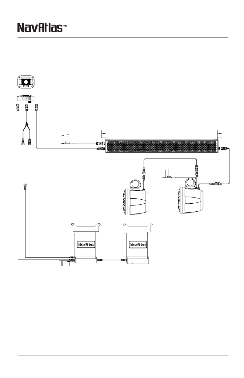
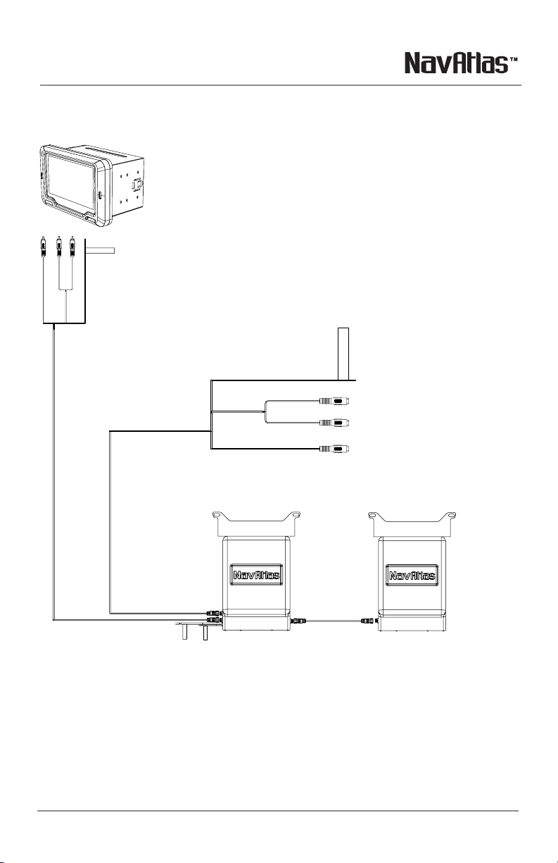
NX310WA NX310WP INSTALLATION
8
Limited One Year Warranty
This warranty gives you specific legal
rights. You may also have other rights
which vary from state to state.
arrants this product to the
original purchaser to be free from defects
in material and workmanship for a period
of one year from the date of the original
purchase.
grees, at our option, during the
warranty period,
to repair any defect in material or
workmanshiporto furnish an equal
new, renewedor comparable product
(whichever is deemed necessary)in
exchange without charges, subjectto
verificationof the defector malfunction and
proofof the date of purchase. Subsequent
replacement products are warranted for the
balance of the original warranty period.
Who is covered?
This warranty is extended
to the original retail purchaser for products
purchased from an authorized NavAtlas
dealer and used in the U.S.A
What is covered? This warranty covers all
defects in material and workmanshipin this
product. The following are not covered:
software, installation/removal costs,
damage resulting from accident, misuse,
abuse, neglect, product modification,
improper installation, incorrect line voltage,
unauthorized repair or failure
to follow instructions supplied with the
product, or damage occurring during return
shipmentof the product.
1. Before you call for service, check the
troubleshooting guide in your owner’s
manual. A slight adjustment of any
custom controls may save youaservice
call.
2. If you require service during the
warranty period, you must carefully
pack the product (preferably in the
original package) and ship it by prepaid
transportation with a copy of the original
receipt from the retailer to an
authorized service center.
3. Please describe your problem in
writing and include your name, a
return UPS shipping address (P.O. Box
not acceptable), andadaytime phone
number with your shipment.
4. For more information and for the
location of the nearest authorized
service center please contact us by one
of the following methods:
•Callus
1-562-946-7471
•E-mail us at
Exclusion of Certain Damages: This
warranty is exclusive and in lieu of any
and all other warranties, expressed or
implied, including without limitation the
implied warranties of merchantability and
fitness for a particular purpose and any
obligation, liability, right, claim or remedy
in contract or tort, whether or not arising
from the company’s negligence, actual
or imputed. No person or representative
is authorized to assume for the company
any other liability in connection with the
sale of this product. In no event shall the
company be liable for indirect, incidental or
consequential damages.
Factory defects include:
· MID/Tweeter not playing or distorting
· Glue/adhesive separating or not holding
correctly
· Tinsel leads not attached/soldered
correctly
· LED not working out-of-box
EXCHANGE ONLY ON FACTORY DEFECTS, PHYSICAL
DAMAGE IS NOT COVERED BY WARRANTY.