manuals.online logo
Brands
  1. Home
  2. •
  3. Brands
  4. •
  5. Navigator Stove Works
  6. •
  7. Stove
  8. •
  9. Navigator Stove Works NSW4 User manual

Navigator Stove Works NSW4 User manual

Navigator Stove Works, Inc.
www.marinestove.com
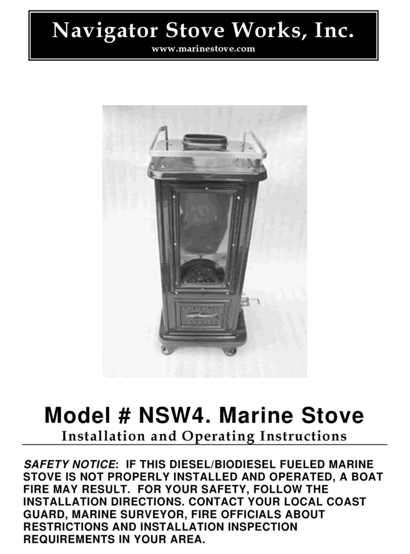
Model # NSW4. Marine Stove
Installation and Operating Instructions
SAFETY NOTICE: IF THIS DIESEL/BIODIESEL FUELED MARINE
STOVE IS NOT PROPERLY INSTALLED AND OPERATED, A BOAT
FIRE MAY RESULT. FOR YOUR SAFETY, FOLLOW THE
INSTALLATION DIRECTIONS. CONTACT YOUR LOCAL COAST
GUARD, MARINE SURVEYOR, FIRE OFFICIALS ABOUT
RESTRICTIONS AND INSTALLATION INSPECTION
REQUIREMENTS IN YOUR AREA.
All manuals and user guides at all-guides.com
all-guides.com
TABLE OF CONTENTS
GENERAL INFORMATION
MARINE INSTALLATION
1. POSSIBLE HAZARDS TO AVOID WHEN USING THE #NSW2.
2. INSTALLATION & SAFETY NOTICE
3. OPERATION
4. MAINTENANCE
5. HEAT EXCHANGER & REFLECTIONS ON A MANUAL DIESEL STOVE
WARNING
DO NOT LEAVE THIS STOVE
UNATTENDED WHILE IN OPERATION
SAFE OPERATION OF THIS
MARINESTOVE IS THE PRODUCT
OF TWO FACTORS:
A CAREFULLY TENDED FIRE AND
PROPER INSTALLATION
General Information
This owner’s manual describes the installation and operation of Navigator’s
Model # NSW4. Marine Stove for Diesel or BioDiesel.
Codes and Regulations compiled from the following sources serve as the basis
for the instructions contained in this document:
ABYC “A-7” *1
NFPA “302” *2
NFPA “211” *3
40 CFR 60 - AAA *4
CAN/CSA B365-M91 *5
2
All manuals and user guides at all-guides.com
When installing, operating, and maintaining your #NSW4, follow the guidelines
given in these instructions. Save these instructions and make them available to
anyone using the stove.
MARINE INSTALLATION
1. Possible Hazards to Avoid
Any use of fire in a boat represents a certain danger. With intense overfiring,
temperatures on the surface of the #NSW4. can exceed 1000°F. (536°C).
Comply with the following guidelines:
•Never overfire the stove. If any part of the stove or chimney glows, you are
overfiring, and a boat fire or serious damage to the stove or chimney could
result. Immediately close the main fuel supply valve if you notice this condition.
•Teach children that the stove is hot and must not be touched.
•Never use gasoline, gasoline-type lantern fuel, charcoal lighter fluid or similar
liquids to start or “freshen up” a fire in the stove. They can ignite with explosive
force, causing bodily injury or death. Keep all such liquids far away from the
stove while it is in use.
•Never use the stove if there are combustible vapours in the boat. The vapours
from certain cleaning fluids, adhesives, and polyurethane paints are a few
examples of combustible vapours.
•Keep combustible materials far away from the stove.
•A vent system or other means shall be provided to allow the discharge from
the boat of hydrogen gas released by the battery. Battery boxes with a cover
that forms a pocket over the battery shall be vented.
•Do not locate traditional marine oil lamps directly over the stove. Oil spillage
onto a hot stove will cause a fire.
•Do not dry clothes over the stove, since they could fall and ignite.
•Fabrics located above and within 39” of the stove used for decorative or other
purposes shall be flame resistant in accordance with NFPA 701, Standard
methods of fire tests for flame-resistant textiles & films.
•To prevent injury, do not allow anyone to use this stove who is unfamiliar with
the correct operation of the stove.
•Avoid creating a “Low Pressure” condition in the space where the stove is
operating, such as by operating an exhaust fan or Dorade vents exhausting
cabin air. A low pressure condition could cause poisonous gasses to be drawn
3
All manuals and user guides at all-guides.com
out of the stove and into the room. Carbon monoxide is toxic, so please follow
the guidelines in this manual to avoid exhaust “roll out” from the burn chamber.
You can prevent a low pressure condition by providing adequate outside
combustion air within 24 inches of the stove. Keep a port, hatch, or window
open while operating the stove!
Install a carbon monoxide monitoring device and maintain it as directed by
the manufacturer.
•If for some reason exhaust “rolls out” of the stove, it might activate a smoke
alarm or carbon monoxide detector.
•Never operate the stove if it is damaged, missing parts, or has been modified
in any way.
•Do not operate the stove during severe storm conditions at sea. Stow cook
surface cover plate.
2. Installation
SAFETY NOTICE: IF THIS Diesel/Biodiesel FUELED MARINE
STOVE IS NOT PROPERLY INSTALLED AND OPERATED, A
BOAT FIRE MAY RESULT. FOR YOUR SAFETY, FOLLOW THE
INSTALLATION DIRECTIONS. CONTACT YOUR LOCAL COAST
GUARD, MARINE SURVEYOR OR FIRE OFFICIALS ABOUT
RESTRICTIONS AND INSTALLATION INSPECTION
REQUIREMENTS IN YOUR AREA.
Please read this entire manual before you install and use your new stove.
Failure to follow instructions may result in property damage, bodily injury, or
even death.
We recommend that you have your #NSW2. Installed by a
professional installer of diesel marine stoves.
Planning the Installation....
If you are considering installing a #NSW4 in a vessel which has a previously
installed stove hearth and/or chimney pipe, it is critical that you have the
existing components inspected for safety.
Safe stove installation involves several aspects: (A) the chimney pipe / deck
iron combination. (B) protecting combustible materials in the vicinity of the
stove. (C) securing the stove. Each of these aspects is equally important for a
safe and secure installation. Consult with a Marine Surveyor.
A. Chimney Pipe
The chimney pipe should be of 4” Dia. stainless steel with a minimum thickness
4
All manuals and user guides at all-guides.com
of 28 gauge. Secure sections of pipe together with three sheet metal screws per
joint to insure that the sections will not separate.
Single-wall smoke pipe and stacks shall have a minimum clearance of 9
inches (23 cm.) from combustible materials including painted materials or
shall be separated by fire resistant thermal insulation that is acceptable to the
authority having jurisdiction. NFPA Standards #302 / 211
Consult with a Marine Surveyor to determine the protection system best suited
for your installation if you cannot maintain the minimum 9” clearance. This
system will commonly consist of a layered panel, made from 20 Ga. sheet
stainless and 5/8” mineral board, spaced 1” from the combustible surface to
which it is attached.
*Exception: at decks equipped with a water iron. (NFPA 302, 6 - 3.3)
Water Deck Iron
Either a bronze or cast iron “water deck iron” shall be used. This traditional
fitting contains water in a trough which surrounds and cools the chimney pipe as
it passes through the deck. Follow manufacturer’s installation & operation
instructions when installing this hardware. Keep the trough filled with water
while operating the stove.
Do NOT install Flue Pipe Draft Damper in the chimney pipe.
Flue Pipe Draft Damper
Do not use aluminum or galvanized pipe as chimney pipe. These materials
cannot withstand the operating temperatures of a fire and can give off toxic
fumes when heated. Round stove pipe must be hand formed to an oval shape
which will then slide onto the stove’s oval flue collar.
The connection between the 4” chimney pipe and the stove’s oval flue
collar should be sealed (from inside) with stove cement after the pipe is
installed. Design the piping so that no more than a total of two 90 degree
bends are utilized. Horizontal runs shall rise at 1/4 inch per foot.
Excessive airflow through the burner may be caused by a larger than 4” chimney
system or by an excessively long chimney. This may be countered and flow
stabilized and limited by using a barometric damper. Signs of excessive flow are
characterized by a loud “low tone - inhale moan” within the burner. If using a
relatively short 4” chimney as one might for a boat (3’ to 4’ of internal cabin
5
All manuals and user guides at all-guides.com
pipe length), the barometric damper is not considered a mandatory accessory.
However it can help to even out any variable internal pressures in a vessel to
maintain an even burn rate at the burner. Wind passing over a boat hull can
induce various pressure spikes within the cabin that can alter airflow through
the burner even though fuel flow remains constant. Dorade vents especially are
sources of negative and positive air pressure that need to be evaluated for air
flow dynamics.
Barometric Pipe Damper
Chimney piping may not be run through a closet, locker or other concealed
space. Always connect this stove to a chimney and vent to the outside of the
vessel. Install a Smoke Head which is designed to minimize water entry and
backdraft. In bad weather do not operate the stove. Safely stow the smoke
head and install a plug which will effectively seal the deck iron‘s opening in
the event of the vessel overturning.
Conical Smoke Head
Do not position the deck iron / smoke head combination within 20” of deck
mounted fuel refill fittings or fuel tank vents. Position the smoke head to
minimize exhaust re-entry into the boat.
B. Clearances to Combustibles
Clearances to Adjacent Combustible Materials....
6
All manuals and user guides at all-guides.com
all-guides.com
Three basic requirements determine the clearance values necessary for the
stove’s installation. Failure to follow these requirements may result in property
damage, bodily injury, or even death.
RULE 1. Exposed materials and finishes within 24” (61Cm) of heat generating
surfaces of the stove shall have a “flame spread index” of not more than 75
as determined in accordance with NFPA 255, Standard Method of Test of
Surface Burning Characteristics of Building Materials.
RULE 2. The sides, back, and front surfaces of the #NSW4. shall have a
minimum clearance of 9” (23Cm) from the exposed combustible
materials and finishes which shall meet the requirements of RULE 1, or
shall be separated by an engineered protection system acceptable to the
authority having jurisdiction. Engineered systems installed for the protection
of combustible material shall reduce the temperature of such materials to
90°F (50°C) rise above ambient. System design shall be based on applicable
heat transfer principles, taking into account the geometry of the system, the
heat loss characteristics of the structure behind the combustible material,
and the possible abnormal operating conditions of the heat-producing
sources.
RULE 3. Minimum clearance to combustible ceilings or materials above the
cook surface of the #NSW4. shall be 36” (92Cm), or shall be separated by an
engineered protection system acceptable to the authority having jurisdiction.
Engineered systems installed for the protection of combustible material shall
reduce the temperature of such materials to 90°F (50°C) rise above ambient.
System design shall be based on applicable heat transfer principles, taking into
account the geometry of the system, the heat loss characteristics of the
structure behind the combustible material, and the possible abnormal operating
conditions of the heat producing sources.
Marine installations will normally require considerable heat-shielding due
to the fact that most boatbuilding materials or finishes located within 9” of
the sides and back of the stove will not have the required rating of FSI 75
or less.
Common Bldg. Materials & Flame Spread Indices:
White Oak 100
Douglas Fir 83 - 100
Eastern White Pine 85
Southern Yellow Pine 130 - 195
Western Spruce 100
1/2” Exterior Douglas Fir Plywood130- 150
3/4” Birch Plywood (veneer core) 114
1/2” Particleboard 156
1/4” Lauan Plywood 150
3/8” FRP (polyester & glass fiber) 200+
K FAC 19 Mineral Fiber Board 25
Insulation material used as part of a clearance reduction system shall also have
7
All manuals and user guides at all-guides.com
a thermal conductivity (K-Value) of 1.0 (Btu-in.) / (ft 2 -hr-°F) or less.
Insulation board shall be formed of noncombustible material.
For example, 1/2” of Thermafiber's K-FAC 19 has an R-Value of 1.28.
TO ORDER PLEASE CONTACT: Foundry Service @ 562-945-6511 /
foundryservice.com / Speak with Dave or Blake.
Also see for further information:
http://hearth.com/articles/64_0_1_0_M1.html
Please Remember....
A combustible is anything that can burn. In the case of stove installations, these
materials may not be plainly visible. Consult your local fire officials if you are
unsure about the combustible nature of a material in the vicinity of your planned
stove installation. Fire resistant materials are difficult to ignite but they will
burn!
Diagrams #1 & #2 give the required clearances that must be maintained from
unprotected combustible materials or finishes.
Diagram #3 illustrates an example of an engineered protection system that
would be used to shield combustible materials.
Consult with your local Marine Surveyor to determine suitable design
parameters for your particular vessel
8
All manuals and user guides at all-guides.com
9
All manuals and user guides at all-guides.com
DIAGRAM #3.
Shield Construction Specifications:
1) Minimum space between shield and combustibles: 1” - 25 mm
2) Minimum clearance along the bottom of shield: 1” - 25 mm
3) Maximum clearance along the bottom of shield: 3” - 75 mm
4) Minimum clearance along the top of shield at ceiling: 3” - 75 mm
5) Edge clearance for ceiling shields: 3” - 75 mm
6) Adhesives used in shield construction must not ignite or
lose adhesive qualities at temperatures likely to be encountered.
7) Mounting hardware must allow full vertical ventilation.
8) Mounting hardware must not be located closer than 200 mm (8 in.)
from the vertical centre line of the appliance.
9) Mounting hardware which extends from the shield surface into
combustibles may be used only at the lateral extremities of the shield.
NOTE: Workshops which fabricate stainless restaurant equipment are great
(cost effective) sources for stainless shielding materials. Make plywood
templates of the required shields and have your local supplier quote a price.
Consider hiding the mineral board edges by bending-over the edges of the
10
All manuals and user guides at all-guides.com
metal by3/4”. Doing so will require no welding at each of the four corners.
Also, consider orienting the surface texture, or grain of the metal either all
horizontal, or all vertical (if you care). This method of dealing with the
shielding issue has yielded high quality results which would have been hard
to match otherwise.
C. Securing the Stove & Fuel Catch Basin.
In order to catch an accidental overflow of fuel from the stove, (in case of a
“flame out” condition in conjunction with the operating valve being left open)
it is mandatory that a metal catch basin of ¾” min. depth be fitted for each
stove installation. This basin shall be plumbed to an overflow sump tank and
shall be able to drain the basin while the vessel is heeled to 30D (drains in
all 4 corners of the basin). The overflow sump tank shall equal or exceed the
capacity of the gravity feed supply tank which should not exceed 2.1Gal.
(8L). If a larger capacity fuel supply tank is required, it must meet the
requirements of NFPA 302 section 5-3 and be able to withstand a pressure of
3 PSI. Please consult a professional marine fuel tank manufacturer.
The stove’s legs have holes which shall allow you to safely anchor it in
place. We suggest that you use slotted, 1/4”-20 stainless steel flat head
machine screws with oversize washers, lock washers, and all-metal locking
nuts. Do not use plain sheet metal screws as they might not hold the stove
in place during a violent storm. Attach the stove to its base before installing
the smoke piping. The flat head screws will need to be slightly bent to allow
them to pass through the catch basin in a perpendicular orientation. Utilizing
a soft jawed vise, allow ¼” of the threaded shank of the fastener to protrude
out of the vise jaws and then bend (with rawhide/copper mallet) the
countersunk head & ¼” portion to 30 degrees off center.
Fuel Catch Basin
Bent ¼-20 FH Machine Screw
11
All manuals and user guides at all-guides.com
all-guides.com
3. Operation.
Before lighting a fire in your new stove, please read the following section
carefully.
Mount the supplied “Warning” plaque in the vicinity of the stove such
that it is clearly visible while operating the stove.
This stove is designed to burn Diesel and BioDiesel.
Do not burn:
•Solid Fuels
•Garbage
•Chemical Chimney Cleaners
•Cardboard or Paper
•Solvents
Burning treated wood, garbage, solvents, colored paper, chemical chimney
cleaners, or trash may result in the release of toxic fumes. Never use
gasoline, gasoline-type lantern fuel, charcoal lighter fluid, or similar liquids
to start or "freshen up" a fire in this heater.
Keep all such liquids far away from the heater while
it is in use.
Fuel Supply Plumbing
A gravity feed, metallic “day tank” of no more than 2.1 gallons shall be used
to supply the stove with fuel.
A fuel shut off valve (bronze ball valve) shall be incorporated into the tank’s
outlet fitting.
Larger tanks must meet the design criteria of NFPA 302 section 5-3 and be
able to withstand a pressure of 3 PSI. Gravity tanks installed in the
compartment with the stove shall be located or shielded so that, when
installed and under continuous operation at maximum heat output, the fuel
temperature shall not rise more than 25D.F above ambient cabin
temperature.
BioDiesel’s fuel viscosity, which impacts the rate of flow through the needle
valves, can alter dramatically due to changes in temperature. The more
stable the tank/fuel temperature, the more stable will be any particular
setting of the control valves. It is recommended that the day tank be installed
in a location where the heat from the stove will not affect it. If the fuel is
heated by the stove, it will change the fuel’s viscosity.
Do not supply fuel directly to the stove by using a pressurized electric “in
line” pump which takes fuel directly from the vessel’s main tank.
12
All manuals and user guides at all-guides.com
Tank Shut Off Valve
In addition to the previously mentioned fuel catch basin, a sump tank shall
be plumbed below the basin to collect an equivalent or greater volume of fuel
provided by the “day tank”. This system will collect fuel in the event of a
“flame out” situation where the operating valve is unintentionally left open
and the burner overflows through its small air inlet holes.
Soft copper or stainless tubing shall be used to supply fuel to the stove.
A“T” fitting shall also be integrated into the supply plumbing with one leg
of the “T’ being a pipe plug. This will allow independent servicing/draining of
the fuel line.
Install an inline fuel filter to catch small debris which could hamper the
operation of the sensitive needle valves. If running Biodiesel, be aware that
at low cabin temperatures the fuel can have a difficult time passing through
the filter media.
3. Controls & Operation
The stove has three user controls; The Decoking Rod and two Fuel Controls.
The Decoking Rod
This rod is positioned within the final brass fitting which admits fuel to the
burner. Its job is to break free any accumulated soot that might prevent free
fuel flow into the burner pot. To use, pull rod fully outward and turn to scrape
any accumulation from the inlet orifice.
Brass Decoking Fitting
13
All manuals and user guides at all-guides.com
The Fuel Flow Controls:
The Operating Valve and the High Limit Valve
The “downstream” valve with the color coded valve stem is called the
OPERATING Valve and is your primary day to day regulating device. The
“upstream” valve is called the HIGH LIMIT Valve and has an adjustment lock
nut which can fix the valve’s position. The HIGH LIMIT valve’s function is to
set the stove’s maximum fuel flow rate.
Rotating the valves in a clockwise manner reduces the fuel flow and
decreases the heat output; counterclockwise opens the valves and increases
the heat output. ONLY VERY SMALL ADJUSTMENTS ARE NEEDED TO
IMPACT HEAT OUTPUT. Adjustments are not immediate; the fuel flow
requires a moment to stabilize before readjusting.
You will determine the best settings for your particular needs as you gain
experience with your stove.
Install the brass decoking fitting to the burner pot using teflon tape. When
fuel is first applied to the plumbing, check to see that the decoke rod is not
leaking fuel. If it is leaking, slightly tighten its compression nut to stop fuel
flow but allow in/out/circular operation of the rod. Check periodically for any
leakage at this point.
The Operating/High Limit Valve assembly then may be secondarily attached
to the Decoke fitting. As your supply tubing exits the High Limit Valve, be
sure to support this plumbing run with appropriate fittings to secure and
rigidify the plumbing.
14
All manuals and user guides at all-guides.com
First starting of the stove and setting the “High Fire”limit.
Once all the plumbing and venting is complete, one may initiate first fire-up.
Burner Core
Remove the wire mesh core from the burner by hand or with the supplied
long T handled hook. Starting with BOTH needle valves CLOSED, proceed
to fully open the downstream color coded OPERATING valve.
Be aware that during this initial HIGH LIMIT setting, one may easily flood
the burner with too much fuel and create a “dirty burn” condition. It will
15
All manuals and user guides at all-guides.com
take time (15 minutes or more) for all the fuel in the burner to be
consumed. If you cause this to happen, close all valves and REMOVE the
cover plate from the stove and let the fire die down naturally. Flames will
likely come up out of the stove trying to seek air to consume. If you keep the
cover plate in place, the stove will try desperately to source air to burn and
emit some very interesting puffing sounds!
Next, “glaze” the bottom of the burner pot with fuel using the HIGH FIRE
valve. Close the valve as soon as fuel has traveled across to the full extents
of the burner bottom. Then, with one wadded-up square of lit toilet tissue,
ignite the pool of fuel and replace the cover plate. The crumpled tissue will
act as a wick and allow the burner to PREHEAT. The preheat process can
easily take 15 minutes before a stable pattern of blue flames exit the burner.
The colder the weather the longer the preheat. During preheat, DO NOT be
tempted to add more fuel.
Once you are satisfied with a stable flame pattern, quickly replace the burner
core using the T handled hook. With this action it’s easy to snuff out the
burner altogether. A second crumpled piece of lit tissue stuck up in the
bottom of the burner core can assist in keeping the vapourizing fuel in the
pot a’light as the core is replaced.
Now with the core in place and burner running smoothly, one needs to watch
for when the burner is running out of fuel and the flame dies down. ONLY at
this point should you start to incrementally open the HIGH FIRE valve. {You
may miss the choice moment first time around so let things cool down and
start at the beginning if need be.} Take your time (45 minutes the first time
around is not uncommon), and let the stove and chimney fully heat up and
increase flow rate until the yellow/orange flame is a maximum of 1/2 the way
up the viewing window.
When you have attained this setting, tighten the locking nut to fix the High
Fire Valve’s maximum setting. With the “top end of burn” established for your
particular fuel type/viscosity and ambient fuel temperature, the OPERATION
valve comes back into play and becomes your primary control for adjustment.
Experiment with the Operation valve to observe how it impacts the burn rate.
It is wise to practice this procedure several times to become familiar with the
sequence and gain confidence with the operation of your stove.
HOT WHILE IN OPERATION. KEEP CHILDREN, CLOTHING,
AND FURNITURE AWAY. DO NOT STORE FUEL WITHIN THE
CLEARANCES LISTED PREVIOUSLY.
16
All manuals and user guides at all-guides.com
all-guides.com
Burner Scraper
4. General Maintenance
Remove the burner core. Scrape the internal burner bottom surface with the
tool provided before each stove fire-up. Vacuum or use a crumpled up ball
of tape to capture the debris. Wear work gloves as burner components may
be sharp! Different fuels will leave different amounts of unburned residue. A
dirty burner pot will not allow the fuel to atomize properly. Keep a small wire
tooth brush handy to remove any accumulated soot off the sides of the pot.
Also, a cup-style wire wheel mounted on a threaded extension shaft
(chucked-up in a drill) is handy for rapidly scouring your pot’s bottom.
Note: the stainless ring within the pot can be removed from the burner pot for
cleaning but it cannot be removed from the stove itself. It will not fit through
the stove’s cover plate opening. Clean the ring and replace in a convex up
orientation. Replace the Burner Core. The core orients with the lifting eye
ring facing upward as well.
The backside of the viewing window can be cleaned most effectively with
toilet tissue. It is best done to a cold stove.
Clean the stove’s porcelain surface with a soft cloth and soap to remove any
accumulation of dirt. Do not use abrasive cleansers or aggressive
scrubbing pads that might scratch the porcelain. Clean the stove when it
is cool to the touch.
As necessary, apply black stove polish or high heat paint to a plain iron
stove to keep it rust free. By polishing your stove just prior to a period of
non-use, you will decrease the chances of your stove rusting.
Also, make sure that water will not find its way down the chimney pipe.
Remove the smoke head and cap the deck iron. Water sitting in the
burner pot can rust-out the bottom of the burner over time.
At least once a year, perform a routine maintenance check. A good time to
do this is when you are cleaning the chimney and smoke head. You should
clean the chimney pipe whenever accumulation of soot is present.
In a dark room, use a strong light to inspect the stove inside and out for
cracks or leaks at corners and joints. Cracked parts should be replaced.
17
All manuals and user guides at all-guides.com
5. Heat Exchanger Option & Reflections on a Manual Diesel Stove
A. If you have ordered your HERRING with the optional pair of hydronic heat
exchangers, here are a few recommendations. First, as the design and
implementation of a radiant hydronic system can be a complex undertaking,
please make sure you have your intended system designed by and or
reviewed by a qualified technician. This will save many hours of possibly
having to reconfigure plumbing/components to achieve your desired heating
results. It’s not necessarily an inexpensive prospect to have to redo things!
The flat SS “tanks” which have a serpentine flow path built into them are
intended for integration into an “open” loop heating system. Please
consult the following reference for clarification:
http://www.home-heating-systems-and-solutions.com/hydronic-heating-
system-expansion-tank.html
The stove may be operated indefinitely with the tanks in an empty state.
Do not “cap-off” the pipe nipples on the backside of the stove when
running the stove dry or with any residual fluid within the exchangers.
Irregardless of overall system design, a temperature and pressure relief
valve or equivalent must be integrated into the heating circuit.
Currently, Navigator Stove’s efforts towards supplying hydronic components
& the associated design of systems ends at the ½” IPS stub outs on the back
of the stove. While we are infinitely fascinated with all that lies past this
border, the making of stoves is our primary goal and we have chosen to set
boundaries to keep our focus.
The ratings for heat output of the exchangers has not been established as
yet. As soon as NSW has any quantitative data or user testimonials as to
general heat output we will be happy to furnish this information.
B. In this modern world where electronic circuits are prompted by sensors
and timers to do this or that job automatically, conversely this stove is
dependent on you for proper operation. You are its ‘brain box” rather than
relying on a printed circuit board full of components to carry out the work.
The operation of a liquid fuel stove is different from the operation of a wood
fired stove. The operator of a manual Diesel stove is responsible for setting
up a stable condition where fuel and air flow rates are optimized to produce a
consistent clean burn. For the sailors out there, one may use the analogy of
balancing head sail to mainsail to direct the boat on a stable course
WITHOUT the use of the tiller. Get the balance right with air to fuel ratio, and
the HERRING will keep a very steady course as long as fuel is present.
Please be sure to shut down the stove when you plan to be away from it for
any length of time. Conditions can change and the stove may need you
there to put things right.
Overall, the HERRING has been designed using a reductive approach – strip
away anything that is not essential for dependable operation. We hope you
enjoy this piece of hardware and come to appreciate its simplicity & beauty.
18
All manuals and user guides at all-guides.com
NSW - 7/24/12
WARNING:
IF THIS DIESEL STOVE IS NOT PROPERLY MAINTAINED, A
CHIMNEY FIRE MAY RESULT. FOR YOUR SAFETY, FOLLOW
THE MAINTENANCE DIRECTIONS AND CLEAN YOUR
CHIMNEY FREQUENTLY.
Appendix
*1 ABYC “A-7”
American Boat & Yacht Council Inc.
“A-7” Liquid and Solid Fuel Boat Heating Systems.
*2 NFPA “302”
National Fire Prevention Association
302, Fire Protection Standard for
Pleasure and Commercial Motor Craft 1998 Edition.
*3 NFPA “211”
National Fire Prevention Association
211, Standard for Chimneys, Fireplaces, Vents, and Solid Fuel-Burning Appliances 2000
Edition.
*4 40 CFR 60 - Subpart AAA
Code of Federal Regulations (USA)
Title 40, Volume 6, Part 60 Revised as of July 1, 1999
Standards of Performance for New Residential Wood Heaters.
*5 CAN/CSA B365-M91
Canadian Standards Association Installation Code for Solid Fuel Burning Appliances.
19
All manuals and user guides at all-guides.com

Other manuals for NSW4

1

Other Navigator Stove Works Stove manuals

Navigator Stove Works HALIBUT User manual

Navigator Stove Works

Navigator Stove Works HALIBUT User manual

Navigator Stove Works NSW4 User manual

Navigator Stove Works

Navigator Stove Works NSW4 User manual

Popular Stove manuals by other brands

Jetmaster INSET STOVE MKIII 60i Installation, operating and servicing instructions

Jetmaster

Jetmaster INSET STOVE MKIII 60i Installation, operating and servicing instructions

L'Artistico Pellicano M14 Installation, use and maintenance manual

L'Artistico

L'Artistico Pellicano M14 Installation, use and maintenance manual

FRANCO BELGE Parisienne 124 03 01 Technical manual

FRANCO BELGE

FRANCO BELGE Parisienne 124 03 01 Technical manual

Whitfield II-T C FS Installating and operation manual

Whitfield

Whitfield II-T C FS Installating and operation manual

TONWERK T-ONE SWING operating instructions

TONWERK

TONWERK T-ONE SWING operating instructions

Vermont Castings Defiant Operation manual

Vermont Castings

Vermont Castings Defiant Operation manual

Gasmate CS601K1 quick start guide

Gasmate

Gasmate CS601K1 quick start guide

Dovre 250DV Installation instructions and operating manual

Dovre

Dovre 250DV Installation instructions and operating manual

Enviro C-10969 owner's manual

Enviro

Enviro C-10969 owner's manual

Nordica CLEO COMBI Bordeaux Instructions for installation, use and maintenance

Nordica

Nordica CLEO COMBI Bordeaux Instructions for installation, use and maintenance

AGA Ellesmere EC5W Installation and operating instructions

AGA

AGA Ellesmere EC5W Installation and operating instructions

Morgan MGS-5515 user manual

Morgan

Morgan MGS-5515 user manual

Yeoman PM302 Fittings guide

Yeoman

Yeoman PM302 Fittings guide

CASATELLI Leonardo 12T GENERAL INFORMATION - WARNINGS - INSTALLATION - MAINTENANCE

CASATELLI

CASATELLI Leonardo 12T GENERAL INFORMATION - WARNINGS - INSTALLATION - MAINTENANCE

Aarrow BK047 user manual

Aarrow

Aarrow BK047 user manual

Harman Stove Company XXV Installation & operating manual

Harman Stove Company

Harman Stove Company XXV Installation & operating manual

TermaTech TT20RS Assembly instructions

TermaTech

TermaTech TT20RS Assembly instructions

Desa AMITY SDVBPD OWNER'S OPERATION AND INSTALLATION MANUAL

Desa

Desa AMITY SDVBPD OWNER'S OPERATION AND INSTALLATION MANUAL

manuals.online logo
manuals.online logoBrands
  • About & Mission
  • Contact us
  • Privacy Policy
  • Terms and Conditions

Copyright 2025 Manuals.Online. All Rights Reserved.