NBK EPC-200-CC User manual

Transceivers-CC-LinkCompliant
InstructionManual

Introduction
Transceivers - CC-Link Compliant (EPC-200-CC)
"1. Safety Precautions"
Use of this Product
・Contact us if you are considering a special use of this product.
・Incorporate and install failsafe functions (emergency stop, monitoring, and similar devices) if
using this product in equipment that could cause a serious accident or loss.
About Disposal
Copying or reprinting all or part of this document in any manner without permission is strictly
prohibited.
Some of the specications described in this document are subject to change without notice
due to product improvements.
Explanation of Symbols
Indicates supplementary written explanation and useful information.
Indicates the reference page(s) in this or related instruction manuals.

Introduction
Check the Packaged Items
Instruction Manuals for Wireless Positioning Units
EPU-COM

Contents
Introduction 1
1 Safety Precautions 5
2 Overview 9
3 Specications 14
4 Installation and Connections 15
5 Maintenance 23
6 Troubleshooting 24
7 Dimensional Outline Drawings 25
8 Radio Wave and EMC Precautions 26
9 Laws and regulations 28

1.1 Essential Precautions
(1)
(2)
(3)
(4)
(5)
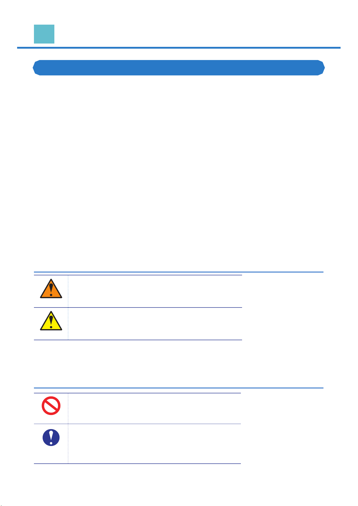
Specic safety precautions are indicated in written form near each WARNING
and CAUTION symbol.
WARNING
Indicates that improper handling can lead to a dangerous
situation that may result in death or serious injury*1.
CAUTION
Indicates that improper handling may lead to minor injury*2
or damage to this product or peripheral equipment.
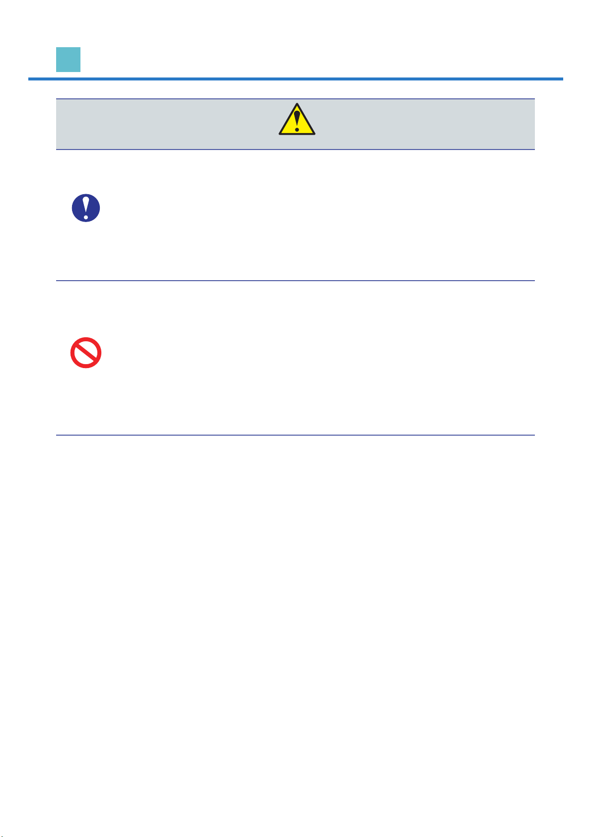
Specic information is indicated in written form near each symbol.
PROHIBITED
Indicates a prohibited action.
Never perform any prohibited work or action.
COMPULSORY
/ INSTRUCTION
Indicates the action is mandatory and must be performed.
Perform the compulsory work/action as indicated.
1 Safety Precautions

1 Safety Precautions
1.2 Precautions Related to Installation and Wiring Work
WARNING
COMPULSORY
/ INSTRUCTION
[Perform as Indicated in Order to Prevent Injury, Electric Shock, Fire, and Failure]
・
・
・
・
PROHIBITED
[Prohibited Actions in Order to Prevent Injury, Electric Shock, Fire, and Failure]
・
・
・
・

1 Safety Precautions
CAUTION
COMPULSORY
/ INSTRUCTION
[Perform as Indicated in Order to Prevent Injury, Electric Shock, Fire, and Failure]
・
・
・
PROHIBITED
[Prohibited Actions in Order to Prevent Injury, Electric Shock, Fire, and Failure]
・
・
・
・
・
・

1 Safety Precautions
1.3 Precautions Related to Operation and Inspection
WARNING
COMPULSORY
/ INSTRUCTION
[Perform as Indicated in Order to Prevent Injury, Electric Shock, Fire, and Failure]
・
・
・
PROHIBITED
[Prohibited Actions in Order to Prevent Injury, Electric Shock, Fire, and Failure]
・
・
・
・
・
CAUTION
COMPULSORY
/ INSTRUCTION
[Perform as Indicated in Order to Prevent Injury and Failure]
・
PROHIBITED
[Prohibited Actions in Order to Prevent Injury, Fire, and Failure]
・
・
[Prohibited Actions in Order to Prevent Unstable Operation]
・
・

2 .1 Product Overview
Transceivers - CC-Link Compliant (EPC-200-CC)
・
・
・
・
・
Connection Example
Transceiver
EPC-200-CC
PLC
Units
EPU-220
EPU-100
Units
EPU-220
Allows up to 32 connections
PC equipment
EPU-COM
* Used for initial settings and controlling
the product from a PC.
RS-485 cable (2-wire type)
USB cable connection
Wireless connection (2.4 GHz)
Wired connection
2 Overview

2 Overview
2.2 Part Names and Functions
This product conforms to the following standards:
① FCC mark: US standards
② CE mark: European standards
③ NCC mark: Taiwan standards
④ KC mark: Korean standards
Monitor LED
Reset switch
USB Port
CC-Link connection
connector
Connects the CC-Link
communication cable
Power Supply/Wired Units
Connection Connector
DIN rail foot
Used for mounting on a DIN rail
Product No.
Serial No.
Specifications
CC-Link settings switch
Connects the 24 VDC power supply or
wired unit
Conformity standard
Configures the CC-Link communication
station number and communication speed
Restarts the transceiver
Connects to a PC with EPU-COM installed
using the included USB cable
①
③
②
④
Antenna
Antenna for wireless
communication
Displays the current status of
the transceiver
Sample Product Nameplate
* The conformity markings shown may vary depending
on the particular product number.
*

2 Overview
2.3 Monitor LED Lighting Patterns
LED
name
LED
color Description
LED
name
LED
color Description
PW
CPU R/W
RUN
L RUN
ERR.
L ERR.
SW
LINE
SD
RD
PW
RUN
ERR.
SW
SD
CPU R/W
L RUN
L ERR.
LINE
RD

2 Overview
2.4 CC-Link Station Number Setting Switch
2.5 CC-Link Transmission Speed Setting Switch
B RATE Communication
speed
0
1
2
3
4
Other

2 Overview
2.6 Block Diagram
CC-Link
CPU
Wireless
communication
module
RS-485
Rotary switch
(Station number
x10)
Rotary switch
(Station number
x1)
Rotary switch
(Baud rate) Reset switch
Low voltage
detection circuit
USB
Memory
Tra㎱ceivers - CC-L㏌k Compliant
(EPC-200-CC)

Operating Environment
Operating
environment
Temperature
Humidity
Transceivers - CC-Link Compliant (EPC-200-CC)
Input voltage
Current consumption
Host connection method
Maximum number of connections
Units connection
method
Wireless
Wired
Wireless
communication
distance
(reference value)
Indoors
Outdoors
External dimensions
(Excluding connectors and antenna)
Mass
(Excluding connectors and antenna)
3 Specications

4 Installation and Connections
4 .1 Installation Requirements
・An indoor environment.
・A place where it is not exposed to direct sunlight (UV rays).
・A place free of continuous vibration.
・A place with little dust and free of exposure to water or oil.
・An environment that facilitates the dissipation of heat.
・A place that allows easy inspection and cleaning.
・A location with an ambient temperature ranging from -5 to 55°C (23 to 131°F) (no
freezing) and an ambient humidity ranging from 20 to 85% RH (no condensation).
・Avoid environments where it may be exposed to water, corrosive atmosphere, ammable
gas, harmful gas, or near ammable materials.
・Be sure to fully consider the installation environment as the transceivers themselves may
be aected by external noise.
・If operating units in a wireless manner, avoid installing the control panel inside metal
housing as the wireless performance will be degraded.
・
・
・Obstacle in the transmission path (Rebar, reinforced concrete, etc.)
・Height dierence in the transmission path
・Installed position is close to the ground
・Metal present nearby
・A lot of radio wave noise in the vicinity

4 Installation and Connections
4.2 Transceiver Installation
4 . 2 .1 Mounting on DIN Rail
DIN Rail Mounting
1
Hook the transceiver's ② Upper tab
onto the top of the ① DIN rail (width
35 mm (1.378 in.)).
2
Press the ③ DIN rail foot against the
DIN rail until it clicks.
Removal from DIN Rail
1
Use a tool such as a athead
screwdriver to pull down the ① DIN rail
foot.
2
Lift up the transceiver and remove it.
It can also be removed by sliding it
along the DIN rail.

4 Installation and Connections
4.2.2 Performing Wireless Communication (Installing Antenna)
1
Remove the ① Protective cover of
the screw and install the included ②
Antenna.
2
Radio waves are radiated vertically
from the antenna axis. After
connecting the antenna, adjust the
angle of the antenna while considering
the directivity of the radio waves.
90°
360° rotation
Illustration of Radio Wave
Adjustment Range of Antenna

4 Installation and Connections
4.3 Connections
4 .3 .1 Connection Example
Connection Example 1 Wired Connection (RS-485)
Connection Example 2 Wireless Connection (2.4 GHz Band Wireless Communication)
0V
EPU-220 EPU-220
EPU-220
Terminating
resistor ON
Terminating resistor OFFTerminating resistor OFF
USB cable
Shield
Terminal
block Terminal
block Terminal
block
0V
0V
+24V
+24V
DA
DB
DG
SLD
FG
CA
CB
CS
SL
EPC-200-CC
Terminating resistor
(120 Ω)
* Used for initial settings and
controlling the product from a PC.
CA
CB
CS
CA
CB
CS
CA
CB
CS
24V
0V
24V
0V
24V
0V
24
0
0V
EPU-220 EPU-220
EPU-220
EPU-100 EPU-100
EPU-100
Terminal
block
Shield
0V
0V
+24V
+24V
DA
DB
DG
SLD
FG
EPC-200-CC
* Used for initial settings and
controlling the product from a PC.
USB cable
CA
CB
CS
CA
CB
CS
SL
CA
CB
CS
24V
0V
24V
0V
CA
CB
CS
24V
0V
24
0

4 Installation and Connections
4.3.2 Wired Connection to Units
Power Supply/Wired Units Connection Connector
Specications
Connector
Manufacturer
Model
Number of pins
Compatible wire
gauge
Connector Pinout
Signal name Description
CA
CB
CS
24
0
SL
Reserved
Installation of Power Supply/Wired Units Connection Connector
1
Insert the ① Connector into the
transceiver.
2
Tighten the two ② Screws with a
athead screwdriver.
(Recommended tightening torque: 0.3
N m (2.65 lbf in.))
This manual suits for next models
1
Table of contents