NEC PG-6200 User manual

3
Before operating this projector, please read this manual carefully and completely.
This manual will provide you with the basic instructions for operation of the
projector. Installation, preliminary adjustments and procedures which require the
opening of the projector and contact with electrical components should be
performed by service personnel. For continued safe and reliable operation, use
only cables supplied by the manufacturer for power. Adhere to all notes and
warnings.
Features
©Multi scan circuit automatically locks on video, superdata from 15 to 69 kHz
(PG-6200/6200G) and graphics signals from 15 to 100 kHz (PG-9200/
9200G).
You can interface video and high resolution RGB signals from various
computers, workstations and graphics boards.
©7" CRTs with deflection angle 90 degrees produce a detailed picture with a
resolution of 160021200 pixels(PG-9200/PG-9200G) and 128021024 pixels
(PG-6200/PG-6200G).
©Newly developed video output circuit makes possible 100 MHz of Video
Bandwidth and 1000 lumens of light output.
©ECP lens produces an image with true color reproduction.
©AKB circuit provides stable white balance.
©Display size can be altered to accommodate any picture size from 60" to 300"
diagonal. In addition to ceiling mounting, floor, desk top and rear installations
are possible. (The ceiling mounting kits can be purchased as an optional item
for ceiling installation.)
©Digital point convergence provides high accuracy for a projecting fine graphic
displays. (This can be purchased as an optional item for the PG-6200/PG-
6200G.)
©On-screen menus provide easy access to adjustment items.
©ISS-6010/ISS-6010G interface allows 10-100 inputs.
©Video system compatible with NTSC, PAL, SECAM and NTSC 4.43.
©Up to 100 convergence patterns can be stored in the stand alone mode in
digital memory.
©Quick copy convergence for fast easy set up from one pre-set signal.
©Built in self diagnostics for on-sight troubleshooting.
©Built in “CROSS HAIR”, “CROSS HATCH”, “DOT”, “WINDOW” and “H
(FOCUS)” test patterns for accurate setup.
©Source information status display.
©The SEQUENCER function allows the projector to automatically select input
signals one after another as programmed by the user.
12345
6
12345
6
12345
6
12345
6
12345
6
123456
INTRODUCTION.

4
INTRODUCTION
Important Safeguards
The following are important safety instructions designed to ensure the long life
of your projector and to prevent fire and shock hazards. Be sure to read these
safety instructions carefully and follow all warnings given below.
Installation
The projector must be installed by trained personnel.
Place the projector on a flat, level surface and in a dry area free from dust and
moisture. Do not place the projector in direct sunlight, near stoves or other heat
radiating appliances. Smoke, steam and exposure to direct sunlight could ad-
versely affect the internal components. Avoid rough handling when moving your
equipment as a strong shock could damage its internal components. If installing
the projector on the ceiling, use only optional ceiling kits (two types) supplied by
the manufacturer. Observe all instructions and warnings. Since installing the
projector on the ceiling requires special techniques and a optional ceiling kit,
users must not try to install it. Contact your dealer for ceiling installation.When
ordering the ceiling kit, specify the part name, PG CMKIT-F or PG CMKIT.
Power supply
The PG-6200 and PG-9200 projector are designed to operate on 120 V 60 Hz,
and the PG-6200G and PG-9200G are designed to operate on 220-240 V 50 Hz
AC power supply. Make sure your local power supply matches these require-
ments before operation.
Handle the power cord carefully and avoid excessive bending. A damaged cord
may cause electric shock or fire. If the projector is not to be used for an extended
period, remove the plug from the power outlet.
Cleaning
Unplug the projector from the power outlet before cleaning.
Clean the cabinet and front panel periodically with a soft cloth. If heavily stained,
use a mild detergent solution. Never use strong detergents or solvents such as
alcohol or thinner to clean your projector.
Lens cleaning: Avoid touching the lens surfaces.
Special coating is applied to the lens surfaces.
Consult your dealer for lens cleaning.
Fire and Shock Precautions
Adequate ventilation must be provided to prevent heat build-up inside the
projector. Make sure the ventilation holes are unobstructed.
Keep the inside of the projector free from foreign objects, such as paper clips,
nails, paper, etc. Do not attempt to retrieve such objects yourself or insert metal
objects such as wire and screw-drivers inside the projector. If a hazardous object
falls inside the projector, unplug it immediately and call a qualified electrical
repairman for removal.
Do not set liquids on top of the projector.

4
12345
6
12345
6
12345
6
12345
6
12345
6
123456
PART NAMES AND FUNCTIONS.
Front Terminal Panel
REMOTE 2
R
G
B
H / V
V
R
EMOTE 1
OPTION 1
S-VIDEO
V
IDEO
POWER
AC INPUT
ACAT
H/V&V
HIGH 75
W
1POWER Switch (Main power)
Press to turn the main power on. The STANDBY indica-
tor will light.
In this condition you can start up the projector by pressing
the POWER ON button on the remote control or the
POWER button on the rear panel.
Press again to turn the main power off.
NOTE: When turning off the main power, first return the
projector to the standby condition by pressing the
POWER OFF button on the remote control or the POWER
button on the rear panel and then turn off the main
POWER switch. These procedures are to protect your
projector and the connected equipment.
2AC INPUT
Connect the supplied power cord here.
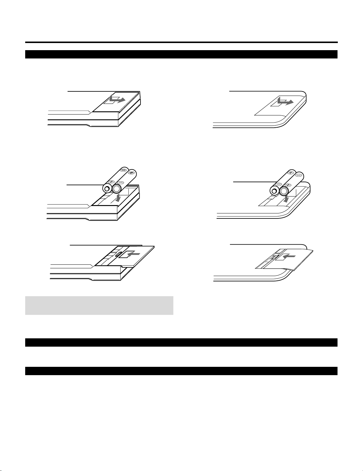
3REMOTE 2 Jack
The supplied full function remote control is connected
here. The wireless control does not work when the remote
cable plug is inserted here.
4R,G,B, H/V and V Input Terminals
Connect R, G, B, H (Horizontal sync) and V (Vertical
sync) outputs of the external equipment (such as the
Switcher). If using a component with a combined sync
(SYNC) output, connect it to the H/V terminal.
5Remote Sensor
Receives the infrared signal from the supplied remote
control when used in the wireless mode.
6REMOTE 1 Terminal
This terminal allows external control of the projector
either from the Switcher or from an external control.
When using the Switcher, connect to the REMOTE 1
terminal on the back of the Switcher.
NOTE: The ISS-6010/ISS-6010G Switcher is compatible
with this projector.
7OPTION 1 Input Terminal
For future system expansion.
8S-VIDEO Input Terminal
Connect to the S-video output of the external equipment
such as VCR with an S-video output. This terminal allows
switching between S2 and S1 VIDEO input modes.
9H/V, V Impedance Switch(HIGH/75 Ω)
Selects the impedance of the H/V and the V terminals. In
normal operation, set at the “75Ω” position.
Slide the switch to the “HIGH” position when inputting a
TTL signal.
0VIDEO Input Terminal
Connect to the video output of the external equipment
such as a VCR or laser disk player.
AACAT Terminal
This is a video output connector for the optional built-in
CCD camera, which is needed to execute the automatic
convergence with the optional ACAT software.
1234A
8 9 0765

5
PART NAMES AND FUNCTIONS
BPOWER Button
Turns the projector on or off when the projector is in the
standby condition (Main Power switch must be on and the
Standby indicator lit).
CCONTROL Button
Used with other buttons, similar to a shift key on a
computer. This is referred to as the CTL button in this
manual and has the same function as the CTL button on
the remote.
DOPERATE Button
Press to display the OPERATE menu. You can select the
following adjustment functions from this menu.
1/ PICTURE 4/ INPUT SELECT
2/ POSITION 5/ SOURCE INFO
3/ SOUND 6/ STATIC
NOTE: ”3/SOUND” is not included in stand alone operate
menu.
EENTER Button
Executes menu selection and switches input.
FEND Button
Exits the adjustment mode.
GDOWN Button
Used to decrease values or move the cursor downward.
When used with the CONTROL button, the DOWN
button works as the CURSOR button on the remote
control unit.
HUP Button
Used to increase values or move the cursor upward. When
used with the CONTROL button, the UP button works as
the CURSOR button on the remote control unit.
INORMAL/LOAD Button
Returns the adjustment data to the standard level (factory
preset level). While holding down the CONTROL button,
press the NORMAL button to display the “LOAD/
CANCEL” menu to select either LOAD (last stored level)
or CANCEL (data cancelled).
JTwo Digit Display
Displays projector error codes. (“00” in normal operation)
KREMOTE Indicator
Flashes to acknowledge when the projector receives a
signal from the remote control.
LSTANDBY Indicator
Lights up when the projector’s main POWER switch is
on. Flashes when the projector might not be connected
with the Switcher correctly or when the Switcher is turned
off.
MPOWER Indicator
Lights up when the projector is turned on.
NRemote Sensor
Receives the signal from the supplied remote control
when used in the wireless condition.
Rear Control Panel
UP NORMAL
/ LOAD
DOWNENDENTEROPERATECONTROLPOWER
POWERSTANDBYREMOTE
BCDEF GHI J KLM N

6
PART NAMES AND FUNCTIONS
Remote control unit
POWER
ON OFF
OPERATE
PICTURE
MUTE
SOUND
MUTE
1 ABC 2 DEF 3 GHI
4 JKL 5 MNO 6 PQR
7 STU 8 VWX 9 YZ /
10 ,.
R
B
ENDCTL
DISPLAY
STATIC
NORMAL ENTER
1 ABC 2 DEF 3 GHIOFFON
4 JKL 5 MNO 6 PQRTEST
7 STU 8 VWX 9 YZ/
ADJUST
OPERATE
10 ,.
SOUND FUNC
PIC FUNC
HELP INFO
INPUT LIST
SOUND MUTE
PIC MUTE
POSITION
KELVINFOCUS
DISPLAY
RGBPOINTSTATIC
PHASETILT
BOW
AMPLIT
LINEAR
STORE
KEYSTN
CTL ENTER END
NORMAL
PINCUS
POWER INPUT
CURSOR
ON
OFF
1
K
R
U
V
S
W
Q
B
0
9
8
4
X
K
L
N
M
P
O
Q
R
T
V
U
W
1
2
3
4
5
6
7
8
9
0
A
B
C
D
J
E
F
G
H
I
S
User Remote Control
RC-6020
Full Function Remote Control
RC-6051
NOTE: The full function remote control is designed for setup
adjustment. Use the user remote control for normal
operation.

7
PART NAMES AND FUNCTIONS
1POWER Buttons (ON/OFF)
Press the ON button to turn the projector on when the
projector is in the standby condition (STANDBY indica-
tor lit). Press the OFF button to return the projector to the
standby condition.
2TEST Button
Press to display the “TEST PATTERN” menu from which
you can select a test pattern.
3ADJUST Button
Press to display the “ADJUST” menu.
4OPERATE Button
Press to display the “OPERATE” menu.
5Backlight Switch
Turns the backlight on and off.
If another button operation is not made within 30 seconds
during the Backlight ON, the Backlight is normally turned
off to conserve the batteries.
6PIC FUNC Button
Press to display the picture adjustment screen.
NOTE: Some function items will not be available
depending on the type of video signal.
7SOUND FUNC Button
Press to display the VOLUME adjustment screen. You
can adjust the volume of the ISS-6010/ISS-6010G
Switcher.
8PICTURE (PIC) MUTE Button
Press to mute the picture. Press again to display the
picture.
9SOUND MUTE Button
Press to mute the sound. Press again to return the sound.
NOTE: This works only with the ISS-6010/ISS-6010G
Switcher.
0DISPLAY Button
Press to turn on or off the on-screen display. Pressing with
CTL eliminates the on-screen display; pressing with CTL
again restores it.
NOTE: Even if the on-screen display may be turned off
with pressing CTL and DISPLAY, any adjustment will
still change the projector’s memory settings. This mode
is available even when an input is switched to another or
the power is turned off using the POWER OFF button on
the remote control.
AFOCUS Button
Press to enter the FOCUS mode.
BSTATIC Button
Press to enter the STATIC mode. You can adjust the static
convergence.
CPOINT Button
(When the point convergence board installed)
Press to enter the POINT mode. You can adjust the point
convergence.
DTILT Button
Press to enter the TILT, SKEW mode. You can adjust the
tilt and the skew of the projected image.
EBOW Button
Press to enter the BOW mode. You can adjust the hori-
zontal and the vertical bow of the projected image.
FAMPLIT Button
Press to enter the AMPLITUDE mode. You can adjust the
horizontal width and the vertical height of the projected
image.
GLINEAR Button
Press to enter the LINEARITY mode. You can adjust the
horizontal and the vertical linearity of the projected
image. Pressing with CTL will bring you to the LINEAR-
ITY-BALANCE adjustment screen.
HKEYSTN Button
Press to enter the KEYSTONE mode. You can adjust the
horizontal and the vertical keystone of the projected
image. Pressing with CTL button will bring you to the
KEY-BALANCE alignment screen.

8
IPINCUS Button
Press to enter the PINCUSHION mode. You can adjust
the horizontal and the vertical pincushion of the projected
image. Pressing with the CTL button will bring you to the
PIN-BALANCE alignment screen.
JPHASE Button
Press to enter the PHASE mode. You can adjust the tilt
and cursor phase.
KINPUT Button
Selects menus and switches input signals.
LHELP Button
Press to display the explanation of the current selected
function and available functions.
MINPUT LIST Button
Press to display the memory list of the recorded input
signals.
NINFO Button
Press to display the various parameters and settings of the
currently displayed image. Pressing with the CTL button
displays some of items available in SETTING MODE.
OKELVIN Button
Press to enter the WHITE BALANCE mode. You can
adjust the white and the black level.
PPOSITION Button
Press to enter the position mode. You can adjust the
horizontal, vertical position and horizontal, vertical
blanking.
QR, G, and B Buttons
Turn each CRT beam on and off separately. When using
with the CTL button, you can select the CRT to be
adjusted during convergence and center focus adjust-
ments. Note that the G button is only on the full function
remote control.
RCURSOR Buttons
Used for increasing and decreasing control levels, cursor
movement and convergence adjustments.
SNORMAL Button
Returns the standard level for each signal. When pressed
once, the confirmation message will be displayed. When
“YES” is selected and ENTER is pressed, the data will be
returned to the standard level. While holding down the
CTL button, press the NORMAL button to display the
“LOAD/CANCEL” menu to select either LOAD (last
stored level) or CANCEL (data cancelled).
TSTORE Button
Memorizes the adjustments setting of each signal sepa-
rately.
When pressed once, the confirmation message “STORE?”
will be displayed. When selecting “YES” and ENTER, the
data will be stored in memory.
UEND Button
Ends the adjustment mode.
VENTER Button
Executes menu selection and switches to selected input.
WCTL Button
Used in conjunction with other buttons, similar to a shift
key on a computer.
XRemote Control Jack
Insert the plug of the supplied remote cable here when the
full function remote control is used in the wired condition.
PART NAMES AND FUNCTIONS

9
PART NAMES AND FUNCTIONS
Battery installation and replacement
User remote control (RC-6020)
1Press down on the battery compartment cover and slide
the cover in the direction of the arrow.
Full function remote control (RC-6051)
1Press down on the battery compartment cover and slide
the cover in the direction of the arrow.
NOTE: The remote control is powered by two alkaline 1.5V
AA batteries.
3Close the battery compartment cover.3Close the battery compartment cover.
2Install the two new batteries, making sure that their
polarity matches the ,.diagrams inside the battery
compartment. Incorrect polarity could damage the unit.
2Install the two new batteries, making sure that their
polarity matches the ,.diagrams inside the battery
compartment. Incorrect polarity could damage the unit.
Remote control cautions
Use the remote control within a distance of about 7m (23 ft.) and at 30 degrees angle left and right.
Handling remote control and batteries
• Do not drop or mishandle the remote.
• Do not get the remote wet. If the remote gets wet, wipe it dry immediately.
• Avoid heat and humidity.
• When not using the remote for a long period, remove the batteries.
• Do not use new and old batteries together, or use different types together.
• Do not take apart the batteries, heat them, or throw them into a fire.
• Avoid using the full function remote control as wireless with the backlight switch ON for an extended period of time. This can
cause short battery life.

8
123456
12345
6
12345
6
12345
6
12345
6
12345
6
123456
PROJECTION CONFIGURATION CHANGE.
Before Installation Change
The projector is electrically and mechanically set for 100 inch diagonal screen, front throw ceiling mount and a projection angle of
12 degrees. If your application is different from the factory setting(for example, ceiling to floor and screen size between 60 and 300
inch), you will have to reconfigure the projector for your application. Follow the change procedures according to the instructions
below.
To change screen size only :
1) Set the focus ring to the proper position.
For 60" screen size
R –––A-2, B-2
G –––A-1, B-2
B –––A-2, B-2
For 200-300" screen size
R –––A-5, B-5
G –––A-1, B-5
B –––A-5, B-5
2) Adujust the angle of the CRT's.
For 60" screen size
Move the CRT to the 60 positon For 200-300" screen size
Move the CRT to the 200 or 300 position
3) Adjust the decorative lens panel.
For 60" screen size
Adjust to match the 60 position For 200-300" screen size
Adjust to match the 200 or 300 position
4) Degauss the projector. See “Degaussing” on page 64 in the set-up manual.
To change to the desk top system (front)
1) Reverse the scan.
H –––1-Red, 2-Blue
V –––1-Brown, 2-Yellow
A –––1-Blue, 2-Red
B –––1-Brown, 2-Yellow
2) Set the focus ring to the proper position.
For 60" screen size
R –––A-2, B-2
G –––A-1, B-2
B –––A-2, B-2
For 200-300" screen size
R –––A-5, B-5
G –––A-1, B-5
B –––A-5, B-5
3) Adujust the angle of the CRT's.
For 60" screen size
Move the CRT to the 60 positon For 200-300" screen size
Move the CRT to the 200 or 300 position
4) Adjust the decorative lens panel.
For 60" screen size
Adjust to match the 60 position For 200-300" screen size
Adjust to match the 200 or 300 position
5) Degauss the projector. Select installation type from ASTIG OUTPUT.
See “ASTIG OUTPUT” on page 62 in the set-up manual.

9
PROJECTION CONFIGURATION CHANGE
To change to the ceiling mount system (rear)
1) Reverse the scan.
H –––1-Red, 2-Blue
V –––1-Yellow, 2-Brown
A –––1-Blue, 2-Red
B –––1-Yellow, 2-Brown
2) Set the focus ring to the proper position.
For 60" screen size
R –––A-2, B-2
G –––A-1, B-2
B –––A-2, B-2
For 200-300" screen size
R –––A-5, B-5
G –––A-1, B-5
B –––A-5, B-5
3) Adujust the angle of the CRT's.
For 60" screen size
Move the CRT to the 60 positon. For 200-300" screen size
Move the CRT to the 200 or 300 position
4) Adjust the decorative lens panel.
For 60" screen size
Adjust to match the 60 position For 200-300" screen size
Adjust to match the 200 or 300 position
5) Degauss the projector. See “Degaussing” on page 64 in the set-up manual.
To change to the front desk top system (rear, 0 projection angle)
1) Reverse the scan.
H –––1-Blue, 2-Red
V –––1-Brown, 2-Yellow
A –––1-Red, 2-Blue
B –––1-Brown, 2-Yellow
2) Set the focus ring to the proper position.
For 60" screen size
R –––A-2, B-1
G –––A-1, B-1
B –––A-2, B-1
For 200-300" screen size
R –––A-5, B-1
G –––A-1, B-1
B –––A-5, B-1
3) Adujust the angle of the CRT's.
For 60" screen size
Move the CRT to the 60 positon. For 200-300" screen size
Move the CRT to the 200 or 300 position
4) Adjust the decorative lens panel.
For 60" screen size
Adjust to match the 60 position For 200-300" screen size
Adjust to match the 200 or 300 position
5) Degauss the projector. Select installation type from ASTIG OUTPUT.
See “ASTIG OUTPUT” on page 62 in the set-up manual.

10
PROJECTION CONFIGURATION CHANGE
Opening Top Cover
CAUTION:
• Be sure to turn off the projector and unplug the power cord before
opening the top cover.
To open the top cover, proceed as follows:
1Loosen two screws A.
• A is a retaining screw.
A
3To close it, push the hinges in the direction of the arrow, then,
close the top cover.
4Tighten the two A screws.
Hinge
2Raise the top front of the projector in the direction of the arrow.
• Be sure to open the top cover until the hinges lock.
Hinge

11
PROJECTION CONFIGURATION CHANGE
Scan Reversal
You will have to reverse the horizontal, vertical and convergence polarity when changing the projector’s configuration.
To reverse the scan, proceed as follows:
CAUTION: Always disconnect the projector from the AC source before reversing the plug. Failure to observe this precaution may
result in electric shock or damage to the projector.
1Open the top cover.
• See Opening Top Cover section.
2Reverse the vertical and horizontal scan.
• To reverse the scan there are two sets of plugs on the sweep board. VR, VG and VB are the vertical connectors(V=vertical and
RGB=color) and HR, HG and HB are the horizontal connectors(H=horizontal and RGB=color).
Remove the plug and turn it 180 degrees, then reinstall. Do this for all three of either horizontal or vertical connectors depend-
ing upon your application (See Table below)
1
VR
Brown
Vertical polarity
connector
Blue
Red
Horizontal polarity
connector
Yellow
2
VG
1
2
1
HB
2
1
HG
2
2
2
Horizontal and Vertical polarity
Connector pin
Setting
Ceiling front
Desk top front
Ceiling rear
Desk top rear
HR, HG, HB
1Lead
Blue
Red
Red
Blue
2Lead
Red
Blue
Blue
Red
VR, VG, VB
1Lead
Yellow
Brown
Yellow
Brown
2Lead
Brown
Yellow
Brown
Yellow
NOTE: The table is for non mirror applications.

12
PROJECTION CONFIGURATION CHANGE
3Loosen the four screws B, then lift the upper chassis(DFC).
• B is a retaining screw.
4Reverse the convergence connectors (AR, BR, AG, BG, AB and BB) on CONV-DRIVE.
See Table below.
Connector pin
Setting
Ceiling front
Desk top front
Ceiling rear
Desk top rear
AR,AG,AB
1Lead
Red
Blue
Blue
Red
2Lead
Blue
Red
Red
Blue
BR, BG, BB
1Lead
Yellow
Brown
Yellow
Brown
2Lead
Brown
Yellow
Brown
Yellow
NOTE: The table is for non mirror applications.
Convergence polarity change
12
Red
Blue
Yellow
Brown
BR
AG
BG
AB
BB
AR
5Close the upper chassis (DFC). Tighten the four screws B.
B

13
C
C
PROJECTION CONFIGURATION CHANGE
Screen Size Change(Adjusting Focus Rings and CRT Angle)
The projector can project an image from 60 to 300 inches diagonal. From the factory the projector is set for ceiling mount, 100 inch
diagonal screen size and a projection angle of 12 degrees. The projector can be used in either 12 or zero degree application.
Before the following procedures, remove the front panel by removing the four screws C whitch hold the front panel. There are two
screws on each side.
CRT
Projection angle
and screen size(Diagonal)
R
Knob G
Knob B
Knob
ABABAB
2
3
4
5
2
3
4
5
2
3
4
5
1
1
1
1
1
1
1
1
1
1
1
1
2
3
4
5
1
1
1
1
2
3
4
5
2
3
4
5
2
3
4
5
1
1
1
1
60" – 90"
91" – 130"
131" – 170"
171" – 300"
60" – 90"
91" – 130"
131" – 170"
171" – 300"
Position of Knobs3Tighten the four screws at the lens.
• Adjusting Focus Rings
There are three sets of adjusting focus rings, two between each CRT and lens.
These focus rings are used for maintaining optimum edge focus for the various screen sizes and projection angles.
*When setting the focus rings or changing CRT angle, you must first remove the front panel.
screws
screws
CAUTION: Be careful not to remove any of the four screws
completely. The falling lens can cause serious injury especially
when the projector is installed on the ceiling.
1Loosen the four screws at the lens.
300200
100
60-300
300200
100
60-300
1 2 3 4 5
A
B
knob A
knob B
Rotate
2Rotate and set the knobs (A and B) to
the right position. The table below lists
which position the knob should be set to
for any given screen size and angle. The
similar table is also on the back of the
top cover.
0°
12°

14
PROJECTION CONFIGURATION CHANGE
• Adjusting Angle of CRTs
To adjust the angle of the CRTs, remove screws G and loosen screws
E and F.
Now you can move the tube and lens assembly to one of the three
other positions. Then replace screws G and tighten screws E and F.
This process needs to be done for the red and blue CRTs. The green
CRT is never repositioned. Use the table below to select the proper
setting for your screen size.
NOTE: The threaded hole marked “60-300” is drilled lengthwise so
you can move the CRT assembly to any screen size. Adjust the red
and blue lens so that the red or blue beam is aligned with the green
beam. After doing this, adjust the static convergence and the lens
focus (see the next page).
Then tighten the screws G.
300200
100
60-300
300200
100
60-300
E E
G F F G
Metal impression stamp screen size
Range of screen size (diagonal)
60-300
60"-300"
100
100"
200
200"
300
300"
• Adjusting Decorative Lens Panels
Before replacing the front panel adjust the decorative lens panels to
match the screen size so that they do not touch the lens barrels or
interfere with the normal operations of the lens.
Loosen the two screws at the top on the two left and right decorative
lens panels, then slide the panels to match the screen size.
• Tighten the screws after completing the above procedures.
• Reinstall the front panel, then replace and tighten the four screws.
300 60
UP
30060
UP
Decorative lens panels
screw screw

15
PROJECTION CONFIGURATION CHANGE
Lens Focus Adjustment
Adjust the center focus and edge focus mechanically to obtain the
best screen focus.
NOTE:
• Plug the power cord and turn on the projector before adjustment.
• The lens focus adjustment must be performed for each lens.
• Select the FOCUS test pattern using the TEST button on the full
function remote control.
Proceed as follows:
1Press the R, G, or B button on the full function remote control to
project the CRT beam to be adjusted.
• You can turn on or off each CRT beam(R, G and B)separately.
2Adjust the CENTER focus.
• Loosen the wing nut A. Rotate the lens using the wing nut A
until the center of the screen is in focus.
When you get the best center focus, tighten the wing nut A.
NOTE: Do not over-tighten the wing nut.
3Adjust the EDGE focus.
• Loosen the wing nut B. Rotate the lens barrel until the edge area
of the screen is focused. Tighten the wing nut B.
4Recheck center focus.
• If it is out of focus, repeat steps 2and 3.
5Repeat steps 1to 4for the other CRTs.
6Close the top cover.
Wingnut B
Wingnut A
B
A
EDGE Focus
CENTER Focus

10
12345
6
12345
6
12345
6
12345
6
12345
6
123456
EXAMPLES OF CONNECTIONS.
CAUTIONS ON CONNECTIONS:
• Unplug the projector and other equipment from the AC
supply before making connections.
• Make sure that the plug of the power cord is properly
connected to the power outlet. A loose connection may cause
hum or noise.
• Confirm your connection layout with the user’s manual
accompanying the equipment to be connected with the ISS-
6010/ISS-6010G Switcher.
NOTE: This projector does not have built-in speakers.
• Make sure that the STANDALONE mode is selected from the CONNECT CONDITION menu. Contact your dealer for the
information in detail.
When Used in Stand Alone Operation
REMOTE 2
R G B H / V V
REMOTE 1 OPTION 1
S-VIDEO VIDEO
POWER AC INPUT
ACAT
H/V&V
HIGH 75Ω
Components with RGB and H/V SYNC
outputs such as a personal computer
VCR or Video disc player
VCR with S-Video outputs
External Control

11
EXAMPLES OF CONNECTIONS
When Used with One Switcher (ISS-6010/ISS-6010G)
Up to 10 input signals can be accepted when the projector is connected to one Switcher. Using the projector with the Switcher
allows easy adjustment and signal selection.
• Make sure that the SW1 LEVEL mode is selected from the CONNECT CONDITION menu. Contact your dealer for the informa-
tion in detail.
• For more information on the Switcher, refer to the user’s manual accompanying the ISS-6010/ISS-6010G Switcher.
• All cables mentioned above are optional.
REMOTE 2
R G B H / V V
REMOTE 1 OPTION 1
S-VIDEO VIDEO
POWER AC INPUT
ACAT
H/V&V
HIGH 75Ω
Optional control cable 15p-15p (CTL-6010)
5BNC-5BNC coaxial cable
From R, G, B, H/V on separate H and V.
on the RGB OUTPUT module
From REMOTE 1 Terminal on the
SYSTEM CONTROL module
The Switcher ISS-6010/ISS-6010G
Personal computer
○○○○○○○○○○○○○○○○○
○○○○○○○○○
Audio equipment
○○○○○○○○○○○○○○○○○○
○○○○○○○○○○○○○○○
VCR
To REMOTE1 To RGB, H/V,V
inputs (BNC)

12
EXAMPLES OF CONNECTIONS
When Used with Two Switchers or More (100 Inputs)
Up to 100 inputs can be accepted using the Switcher.
How to make connections:
SLAVE 1
• • • • • •
10 inputs
SLAVE 2
• • • • • •
10 inputs
SLAVE 10
• • • • • •
10 inputs
SLAVE 3
SLAVE 9
• • • • • • • • • • • • • • • • • • • •
Signal SWITCHER Signal
OPTION (PC)
REMOTE
CONTROL
REMOTE 1
REMOTE 2
Signal
REMOTE 1
REMOTE 2
REMOTE 1
REMOTE 2
Signal
REMOTE 1
REMOTE 2
To SLOT 1
To SLOT 2
To SLOT 10 Signal
REMOTE 1
MASTER
SWITCHER
To REMOTE 2 REMOTE 1
OPTION
(PC)
PROJECTOR
1Connect the REMOTE 1 terminal of the master Switcher
to the REMOTE 1 of the projector using the optional
control cable (15p-15p/CTL-6010).
2First connect the REMOTE 2 terminal of the master
Switcher to the REMOTE 1 terminal of the first slave
Switcher using the same optional control cable as men-
tioned above. Second connect the REMOTE 2 terminal of
the first slave to the REMOTE 1 of the second slave, and
the REMOTE 2 terminal of the second slave to the
REMOTE 1 terminal of the third slave (— and the
REMOTE 2 of the ninth slave to the REMOTE 1 of the
tenth slave). Connect all the Switchers with optional
control cables.
• Make sure that the SW2 LEVEL mode is selected from the CONNECT CONDITION menu. Contact your dealer for the informa-
tion in detail.
• Refer to the user’s manual accompanying the Switcher.
• Cables mentioned are not included with the projector.
NOTE:
• Be sure to set all the Slide switches (S8603) of the
Switcher to RS-422 positions. Set the one on the last slave
Switcher to the appropriate position to match the con-
nected equipment such as a personal computer. (RS-422/
RS-232C for PC control of projector)
• Set the DIP switch S8601 of the Switcher.
• This operation does not work with the NEC GP-3000/GP-
3000G and the GP-5000/GP-5000G projectors.

13
EXAMPLES OF CONNECTIONS
Set the DIP switch (S8601) of the Switcher as follows:
The Projector
Slot 1 of the Master
Slot 2 of the Master
Slot 3 of the Master
Slot 4 of the Master
Slot 5 of the Master
Slot 6 of the Master
Slot 7 of the Master
Slot 8 of the Master
Slot 9 of the Master
Slot 10 of the Master
Master
Slave 1
Slave 2
Slave 3
Slave 4
Slave 5
Slave 6
Slave 7
Slave 8
Slave 9
Slave 10
12345678
OPEN
12345678
OPEN
12345678
OPEN
12345678
OPEN
12345678
OPEN
12345678
OPEN
12345678
OPEN
12345678
OPEN
12345678
OPEN
12345678
OPEN
12345678
OPEN
ISS-6010
ISS-6010G Output to Setting of S8601
NOTE: Slave numbers 1 to 10 must correspond to the master’s slot numbers 1 to 10.
This manual suits for next models
5
Table of contents
Other NEC Projector manuals

NEC
NEC PA622U User manual

NEC
NEC NP4001 Operation and maintenance manual

NEC
NEC NP1250 Series User manual

NEC
NEC VT770 Series User manual

NEC
NEC NP-P350W User manual

NEC
NEC UM351W User manual

NEC
NEC DT100 - MultiSync XGA LCD Projector User manual

NEC
NEC UM301W User manual

NEC
NEC MultiSync MT810 User manual

NEC
NEC GT5000 Series User manual