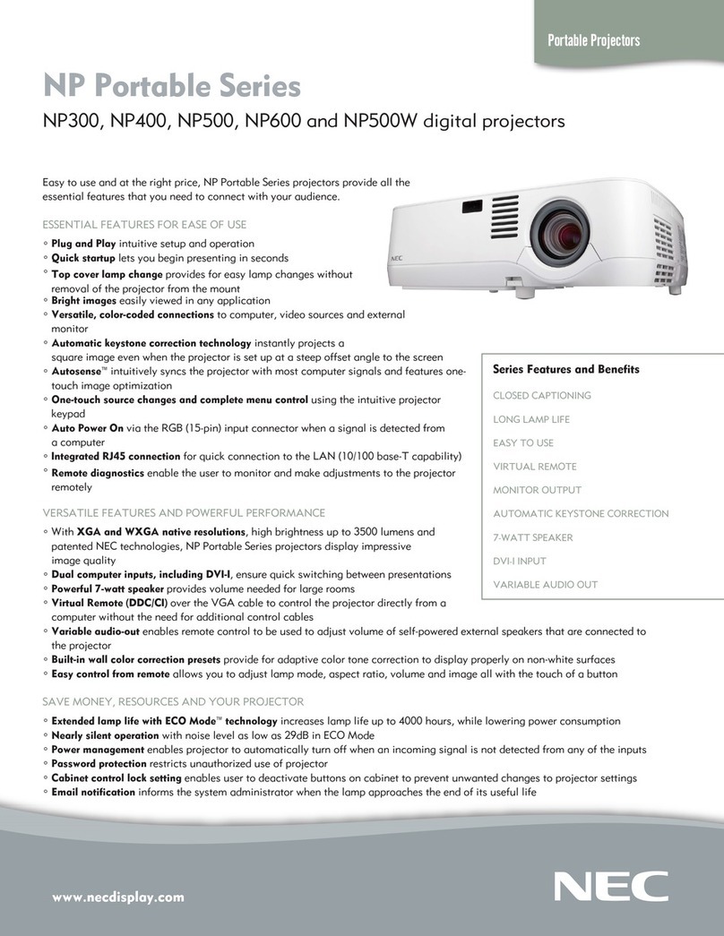
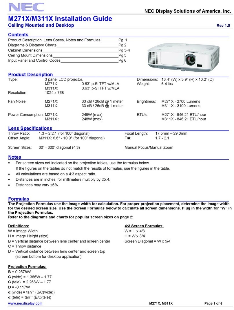
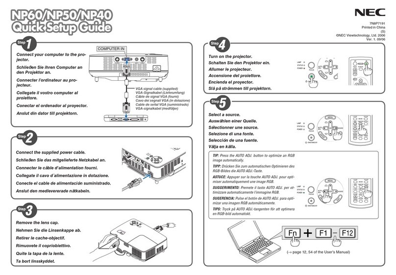
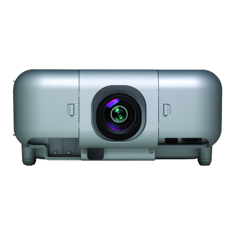
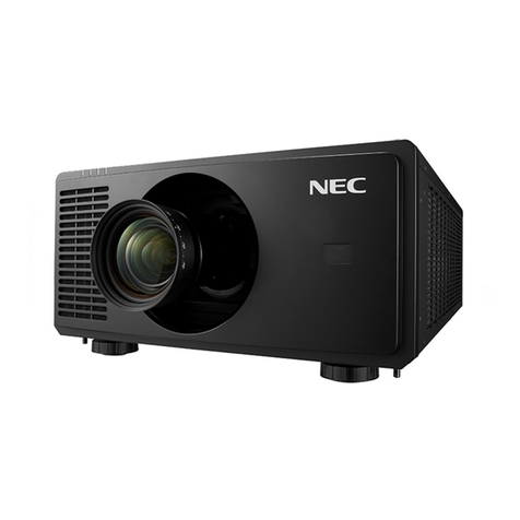
NEC PH1201QL User manual

Model No. NP-PH1201QL
INSTALLATION AND QUICK-START GUIDE
CONNECTION GUIDE
OPERATING GUIDE
REFERENCE GUIDE
Projector
PH1201QL
User’s Manual

page i
Model No. NP-PH1201QL
About This Document
Follow the instructions in this manual carefully to ensure safe and long-lasting use of the projector.
Symbols used in this manual
Many pages in this document have a dedicated area for notes. The information in that area is accompanied by the following symbols:
WARNING: this symbol indicates that there is a danger of physical injury to yourself and/or damage to the equipment unless
the instructions are closely followed.
ELECTRICAL WARNING: this symbol indicates that there is a danger of electrical shock unless the instructions are closely
followed.
LASER WARNING: this symbol indicates that there is a potential hazard of eye exposure to laser radiation unless the
instructions are closely followed.
NOTE: this symbol indicates that there is some important information that you should read.
Product revision
Because we at NEC continually strive to improve our products, we may change specications and designs, and add new features without
prior notice.
Legal notice
Trademarks and trade names mentioned in this document remain the property of their respective owners.
NEC disclaims any proprietary interest in trademarks and trade names other than its own.
Notes

page ii
Model No. NP-PH1201QL
Laser Information
Caution-useofcontrolsoradjustmentsorperformanceofproceduresotherthanthosespeciedhereinmayresultin
hazardous radiation exposure.
NEC Display Solutions, Ltd.
4-28, Mita 1-chome, Minato-ku, Tokyo, Japan
Contact address for EMEA
NEC Display Solutions Europe GmbH
Landshuter Allee 12-14 80637 Munich, Germany
This device complies with part 15 of the FCC Rules.
Operation is subject to the following two conditions:
(1) This device may not cause harmful interference, and
(2) This device must accept any interference received,
including interference that may cause undesired operation.
Complies with FDA performance standards for laser products
except for deviations pursuant to Laser Notice No. 50,
dated June 24, 2007
CAN ICES-3 (A)/NMB-3(A)
Tegangan dan Frekuensi : 200-240V ~ 50/60Hz
Produksi UK
Made in UK
This cabinet is constructed of Metal(AL) and Plastic(PC/ABS)
E176726
NWGQ
115-364C
Notes

page iii
Model No. NP-PH1201QL
Introduction
Your projector has the following key features:
• 4K resolution up to 60 fps.
• Full 4K 3D display capability.
• Scaling 2K resolution to 4K resolution.
• Quad 3G-SDI interface for 4K 60fps.
• Control via LAN and RS232.
• Motorised lens mount.
A serial number is located on the product label. Record it here:
Notes

page iv
Model No. NP-PH1201QL
CONTENTS
INSTALLATION AND QUICK-START GUIDE ..............................1
WHAT’S IN THE BOX? ................................................................... 3
POWER SUPPLY............................................................................ 4
AC power work specications ............................................................... 4
AC power supply equipment ..................................................................... 4
AC power supply cable for the projector....................................................... 5
Connector............................................................................................ 6
Connecting the power supply................................................................ 7
PROJECTOR OVERVIEW ............................................................... 8
Front and rear views ............................................................................. 8
Control panel......................................................................................... 9
Control panel button indicators ........................................................... 10
Status indicators.................................................................................. 11
POSITIONING THE SCREEN AND PROJECTOR........................... 12
Tilting restrictions ................................................................................ 13
Pitch................................................................................................. 13
Roll .................................................................................................. 13
LENS ASSEMBLY AND FITTING................................................... 14
Assembling the lens............................................................................ 14
Inserting a new lens ............................................................................ 16
Removing the lens .............................................................................. 19
CLEANING AND REPLACING THE FILTERS ................................ 21
General notes...................................................................................... 21
Cleaning the air lters ........................................................................... 21
Replacing the air lters.......................................................................... 21
Rear lters........................................................................................... 22
Front lter............................................................................................ 24
Reset the air lter usage time ............................................................. 26
OPERATING THE PROJECTOR.................................................... 27
Switching the projector on................................................................... 27
Switching the projector off................................................................... 28
Selecting a title or test pattern............................................................. 29
Selecting a title.................................................................................... 29
Selecting a test pattern.......................................................................... 30
Adjusting the lens................................................................................ 31
Adjusting the brightness...................................................................... 32
CONNECTION GUIDE ............................................................................33
SIGNAL INPUTS .......................................................................... 35
SDI and DVI inputs.............................................................................. 35
3D Sync ............................................................................................ 36
Indicators on the terminal panel............................................................... 37
EDID on the DVI inputs....................................................................... 38
Using HDMI/DVI/DisplayPort switchers with the projector............................... 38
CONTROL CONNECTIONS........................................................... 39

page v
Model No. NP-PH1201QL
OPERATING GUIDE ................................................................................41
USING THE CONTROL PANEL ..................................................... 43
LCD display overview.......................................................................... 43
In STANDBY mode .............................................................................. 43
In operation........................................................................................ 43
When showing menus........................................................................... 44
Locking and unlocking the control panel............................................. 45
Working with menus........................................................................... 46
Entering alphanumeric values ................................................................. 46
USING THE PROJECTOR............................................................. 47
Title Select menu ................................................................................ 47
Selecting a test pattern.......................................................................... 47
Conguration menu............................................................................. 48
Light Setup ........................................................................................ 48
Lens Control....................................................................................... 48
Reset................................................................................................ 48
Information menu ................................................................................ 49
Light Output ....................................................................................... 49
Preset Button...................................................................................... 49
Usage............................................................................................... 49
Error Code ......................................................................................... 49
Version ............................................................................................. 50
IP Address ......................................................................................... 51
Setup Date......................................................................................... 51
Option Status...................................................................................... 51
REFERENCE GUIDE................................................................................53
THE DMD™.................................................................................. 55
CHOOSING A LENS ..................................................................... 57
SCREEN REQUIREMENTS........................................................... 58
Fitting the image to the DMD™........................................................... 58
Diagonal screen sizes......................................................................... 59
Fitting the image to the screen............................................................ 60
Positioning the screen and projector................................................... 61
POSITIONING THE IMAGE........................................................... 62
ASPECT RATIOS EXPLAINED...................................................... 64
APPENDIX A: LENS PART NUMBERS.......................................... 65
APPENDIX B: SUPPORTED SIGNAL INPUT MODES .................... 66
Supported 4K signals - Option board.................................................. 66
Screen allocation of Option board input signals ........................................... 67
APPENDIX C: MENU MAP............................................................ 68
APPENDIX D: WIRING DETAILS .................................................. 70
Signal inputs - option board ................................................................ 70
DVI .................................................................................................. 70
3G-SDI In .......................................................................................... 71
Control connections ............................................................................ 72
LAN ................................................................................................. 72
RS232 .............................................................................................. 72
3D Sync IN and 3D Sync OUT ................................................................ 72
CONTENTS (continued)
page vi
Model No. NP-PH1201QL
TECHNICAL SPECIFICATIONS .................................................... 73
Models................................................................................................. 73
Inputs and outputs............................................................................... 74
Bandwidth ........................................................................................... 74
Remote control and keypad ................................................................ 74
Automation control .............................................................................. 74
Color temperature ............................................................................... 74
Lenses................................................................................................. 75
Lens mount ......................................................................................... 75
Mechanical mounting .......................................................................... 75
Orientation........................................................................................... 75
Electrical and physical specications.................................................. 76
Safety & EMC regulations................................................................... 76
CAD drawings ..................................................................................... 77
NEC CONTACTS .......................................................................... 78
CONTENTS (continued)
Model No. NP-PH1201QL
This page is intentionally left blank.

Model No. NP-PH1201QL
Projector
PH1201QL
Installation and Quick-Start Guide

Model No. NP-PH1201QL
Installation and Quick-Start Guide
IN THIS GUIDE
IN THIS GUIDE
What’s In The Box?............................................................................................. 3
Power Supply........................................................................................................ 4
ACpowerworkspecications ...................................................................................4
AC power supply equipment ............................................................................................. 4
AC power supply cable for the projector ........................................................................... 5
Connector ......................................................................................................................... 6
Connecting the power supply....................................................................................7
Projector Overview............................................................................................. 8
Front and rear views ...................................................................................................8
Control panel ...............................................................................................................9
Control panel button indicators...............................................................................10
Status indicators .......................................................................................................11
Positioning The Screen And Projector....................................................... 12
Tilting restrictions.....................................................................................................13
Pitch ................................................................................................................................13
Roll..................................................................................................................................13
Lens Assembly And Fitting ............................................................................ 14
Assembling the lens .................................................................................................14
Inserting a new lens..................................................................................................16
Removing the lens ....................................................................................................19
Cleaning And Replacing The Filters ........................................................... 21
General notes ............................................................................................................21
Cleaning the air lters .....................................................................................................21
Replacing the air lters ...................................................................................................21
Rearlters .................................................................................................................22
Frontlter ..................................................................................................................24
Resettheairlterusagetime ..................................................................................26
Operating The Projector................................................................................. 27
Switching the projector on.......................................................................................27
Switching the projector off.......................................................................................28
Selecting a title or test pattern.................................................................................29
Selecting a title................................................................................................................29
Selecting a test pattern ...................................................................................................30
Adjusting the lens .....................................................................................................31
Adjusting the brightness..........................................................................................32

page 3
Model No. NP-PH1201QL
Installation and Quick-Start Guide
WHAT’S IN THE BOX?
What’s In The Box?
Make sure your box contains everything listed. If any pieces are missing, contact your dealer.
Please save the original box and packing materials if you ever need to ship your projector.
Notes
NP-PH1201QL projector (without lens) x 1
lens holder x 1
service keys x 2 User Manual CD x 1 Important Information x 1
lens gearbox cover x 1
(incl. M2 socket head screws x 2)

page 4
Model No. NP-PH1201QL
Installation and Quick-Start Guide
POWER SUPPLY
Power Supply
The power cable is not included with the projector. Refer to the AC power work specications section below and provide the necessary
power cable.
AC power work specications
AC power supply equipment
Do not use any voltage other than those shown below for the AC power supply connected to the projector:
• 200–240V AC, single phase, power, 50/60Hz
Notes
Carefully read the contents
described in this section before
connection and connect the
cables according to the proper
procedure. Inappropriate handling
may cause fatal, serious or other
bodilyinjuriesduetoreor
electric shock.
Before connecting the power
cables, check that the main power
switch of the projector is turned
off. Implement the connection
with AC power shut off.
Be sure to ground the equipment
to ensure safety. Use a power
cable that meets the standards
and power supply voltage of the
country where you are using the
projector and always connect the
equipment to the ground. If the
ground is not connected, it may
cause electrical shocks.
When connecting the power
cable plugs to the AC IN and the
electrical outlet, securely insert
the plugs all the way in. If the
connection between the power
cable plug and the electrical
outlet is loose, the plug area may
generate heat, causing burns and
accidents.
Users in North America:
Use a power cable no longer
than 4.5 m / 14.76 ft according to
National Electrical Code.

page 5
Model No. NP-PH1201QL
Installation and Quick-Start Guide
POWER SUPPLY
AC power supply cable for the projector
The projector is equipped with an IEC60320 C20 inlet to connect an AC power supply cable. Use an IEC60320 C19 compliant AC power cable
connector and ensure that the connector meets the following current capacity specications.
Power supply voltage Projector input current Power cable current capacity
AC 200-240 V 8.2 A 250 V 15 A or higher
Furthermore, use cables, plugs and connectors that are suitable for the regulations of the country of installation, as shown in the following table.
Germany Japan
Plug: CEE7 Cable: H05VV-F 3G1.5 Connector: IEC 320 C19 Plug: JIS C 8303 Cable: VCTF 3 x 2.0mm Connector: IEC 320 C19
USA China
Plug: NEMA 6-15P Cable: SJT 3 x AWG 14 Connector: IEC 320 C19 Plug: GB2099 Cable: RVV 300/500 Connector: GB17465.1
Notes
Carefully read the contents
described in this section before
connection and connect the
cables according to the proper
procedure. Inappropriate handling
may cause fatal, serious or other
bodilyinjuriesduetoreor
electric shock.
Before connecting the power
cables, check that the main power
switch of the projector is turned
off. Implement the connection
with AC power shut off.
Be sure to ground the equipment
to ensure safety. Use a power
cable that meets the standards
and power supply voltage of the
country where you are using the
projector and always connect the
equipment to the ground. If the
ground is not connected, it may
cause electrical shocks.
When connecting the power
cable plugs to the AC IN and the
electrical outlet, securely insert
the plugs all the way in. If the
connection between the power
cable plug and the electrical
outlet is loose, the plug area may
generate heat, causing burns and
accidents.
Users in North America:
Use a power cable no longer
than 4.5 m / 14.76 ft according to
National Electrical Code.
1Cable
2Plug
3Connector
2
3
1

page 6
Model No. NP-PH1201QL
Installation and Quick-Start Guide
POWER SUPPLY
Connector
Dimensions of the connector of the power cable are shown below.
Notes
Carefully read the contents
described in this section before
connection and connect the
cables according to the proper
procedure. Inappropriate handling
may cause fatal, serious or other
bodilyinjuriesduetoreor
electric shock.
Before connecting the power
cables, check that the main power
switch of the projector is turned
off. Implement the connection
with AC power shut off.
Be sure to ground the equipment
to ensure safety. Use a power
cable that meets the standards
and power supply voltage of the
country where you are using the
projector and always connect the
equipment to the ground. If the
ground is not connected, it may
cause electrical shocks.
When connecting the power
cable plugs to the AC IN and the
electrical outlet, securely insert
the plugs all the way in. If the
connection between the power
cable plug and the electrical
outlet is loose, the plug area may
generate heat, causing burns and
accidents.
Users in North America:
Use a power cable no longer
than 4.5 m / 14.76 ft according to
National Electrical Code.
7+0,5
-
0
28
+0
-
0,9 20
+0
-
0,7
6,0 +0,5
-
0
2,5 +0,5
-
0
2,5 +0,5
-
0
8±0,2
13 ±0,2
Unit: mm
R3.5 min
20 min

page 7
Model No. NP-PH1201QL
Installation and Quick-Start Guide
POWER SUPPLY
Connecting the power supply
When the projector is viewed from the back, the AC mains
inlet 1is located on the right hand side, toward the rear.
Make sure the power switch 2above the inlet is in the
OFF position, then push the mains connector in rmly.
12
Notes
Ensure that the power outlet
includes a ground connection as
this equipment MUST be earthed.
Handle the power cable carefully
and avoid sharp bends. Do not
use a damaged power cable.

page 8
Model No. NP-PH1201QL
Installation and Quick-Start Guide
PROJECTOR OVERVIEW
Projector Overview
Front and rear views
1 Airinletandlter
2SYSTEM status indicator
When the projector is operating normally, this
indicator lights green or orange. If an error
occurs, the light becomes red. Depending on the
scenario, the light can be steady or ashing.
3LIGHT status indicator
Turns on when the light source is switched on.
4Lens
5Air outlet
6 Airinletandlter
7Air outlet
8Power switch and power connection
9Control panel with LED screen
10 Connections
11 Adjustable feet
Notes
Front view
4
32
5
1
Rear view
11
7 86
11
9 10 10

page 9
Model No. NP-PH1201QL
Installation and Quick-Start Guide
PROJECTOR OVERVIEW
Control panel
1LCD display
2KEY LOCK button (with indicator)
3Arrow buttons
4MENU button
5ENTER button
6not used in this conguration
(except for entering alphanumeric values)
7LIGHT button
8not used in this conguration
9POWER button (with indicator)
10 EXIT button
11 DOUSER button (with indicator)
12 LIGHT ON / OFF button (with indicator)
13 not used in this conguration
14 Preset buttons 1 to 8 (with indicators)
Notes
See Entering alphanumeric values
in the Operating Guide.
1
10
4
7
14
3
6
2
9
12
13
8
11
5

page 10
Model No. NP-PH1201QL
Installation and Quick-Start Guide
PROJECTOR OVERVIEW
Control panel button indicators
1KEY LOCK
Behavior Meaning
Off Key lock is inactive.
On Key lock is activated.
2POWER ON / OFF
Behavior Meaning
Off
The projector is switched off from the power supply
or in STANDBY mode.
Flashing
green
The projector is warming up (preparing to switch ON)
or cooling down (preparing to switch OFF).
Steady
green The projector is switched on.
3DOUSER ON / OFF
Behavior Meaning
Off The douser is opened.
Steady
green The douser is closed.
4LIGHT ON / OFF
Behavior Meaning
Off The light source is switched off.
Steady
green The light source is switched on.
5Presets
Behavior Meaning
Off The title is not assigned to the projector.
Steady
white
The title is assigned to the projector but is not
currently in use.
Steady
green
The title is assigned to the projector and is currently
in use.
Notes
1
5
4
2
3

page 11
Model No. NP-PH1201QL
Installation and Quick-Start Guide
PROJECTOR OVERVIEW
Status indicators
1LIGHT status indicator
Behavior Meaning
Off The light source is switched off.
On The light source is switched on.
2SYSTEM status indicator
Behavior Meaning
Off The projector is switched off.
Flashing green The projector is warming up. The douser is closed and the light source is off.
Steady green The projector is switched on.
Flashing amber The projector is cooling down.
Steady amber The projector is in standby.
Flashing red Error, projection cannot continue. Check LCD screen for error message.
Flashing red, with buzzer Error with safety implications. Projection cannot continue. Check LCD screen for error message.
Steady red Non-fatal error, projection may continue. Check LCD screen for error message.
Notes
21

page 12
Model No. NP-PH1201QL
Installation and Quick-Start Guide
POSITIONING THE SCREEN AND PROJECTOR
Positioning The Screen And Projector
Installation should be carried out by authorised personnel only.
1. Install the screen, ensuring that it is in the best position for viewing by your audience.
2. Mount the projector, ensuring that it is at a suitable distance from the screen for the image to ll the screen. Set the adjustable feet so that
the projector is level, and perpendicular to the screen.
The drawing below shows the bottom of the projector. The positions of the feet for table mounting, and the xing holes for ceiling mounting
are clearly visible. The illustration also shows the positions of the four handles which facilitate safe carriage.
1Four adjustable feet
2Six M6 holes for ceiling mount (set A)
The screws should not penetrate more than 15 mm into the
body of the projector.
3Handles for safe carriage
4Six M6 holes for ceiling mount (set B)
The screws should not penetrate more than 15 mm into the
body of the projector.
1
2
1
1
1
2
2
2
2
2
3
3
3
3
4
4
4
4
44
Notes
Always allow the projector
to cool for 5 minutes before
disconnecting the power or
moving the projector.
Ensure that there is at least 30
cm (12 in) of space between the
ventilation outlets and any wall,
and 10 cm (4 in) on all other
sides.
Projectors are not designed to
be stacked on top of each other
unless a rigging frame is used.
3
Table of contents
Other NEC Projector manuals

NEC
NEC LT156 - MultiSync XGA DLP Projector User manual

NEC
NEC NP600 Series User manual

NEC
NEC M402W User manual

NEC
NEC LT260 Series Operating manual

NEC
NEC NP03CM Guide

NEC
NEC NP110 - SVGA DLP Projector User manual

NEC
NEC VT660 Operating manual

NEC
NEC PX803UL-WH User manual

NEC
NEC VT37 User manual

NEC
NEC NP-UM330W Series User manual

NEC
NEC DT100 - MultiSync XGA LCD Projector User manual

NEC
NEC PX750U2 User manual

NEC
NEC PH1202HL User manual

NEC
NEC MultiSync VT440 User manual

NEC
NEC Nighthawk XT9000 User manual

NEC
NEC VT575 Series User manual

NEC
NEC MT50 Assembly instructions

NEC
NEC NP100 - SVGA DLP Projector User manual

NEC
NEC DLP CINEMA NC1600C User manual

NEC
NEC LT35 - INSTALLTION GUIDE User manual