E-3
40"-100"
90˚
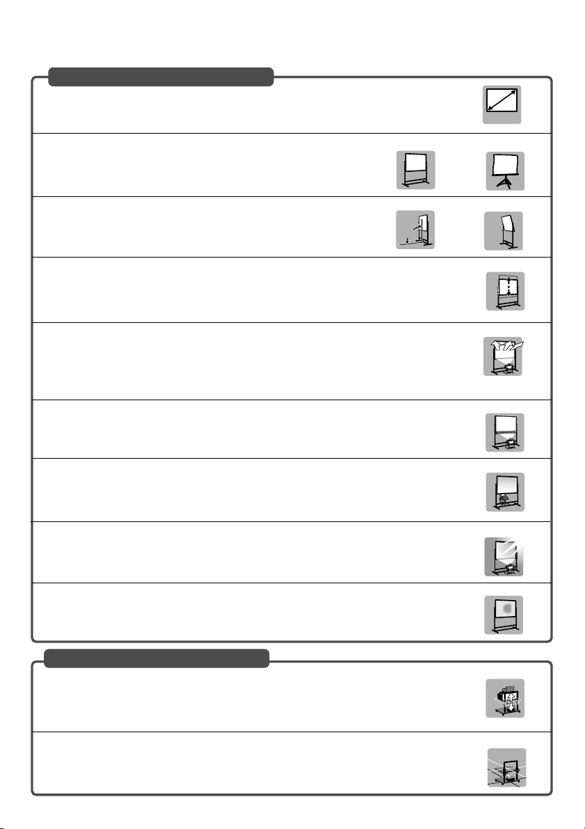
Screens Suited
•Screens with a soiled, scratched, or discolored area will not produce a clean image. Care
should be used in the handling of the screen.
Recommended Not recommended
Recommended Not recommended
Recommended
Not recommended
Not recommended
Not optimal
Not recommended
Not recommended
•Use a panel or tension type screen that has a flat surface.
Do not use roll type screens and other screens that bend or form a wavy
surface easily. Doing so will result in increased distortion of the projected
image.
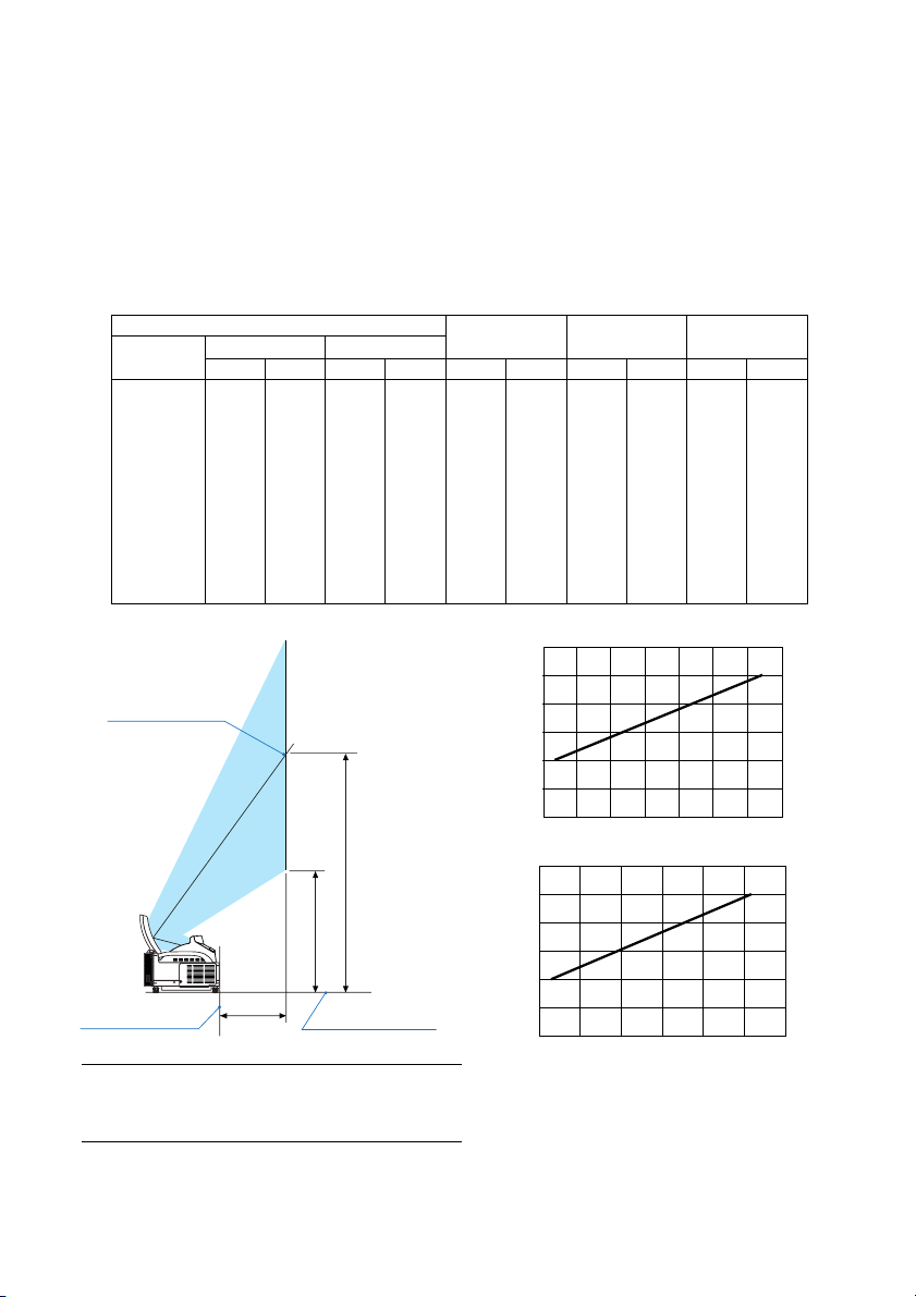
•The projector can accommdate screen sizes from 40” (81.3 cm/32.0” W ⳯61.0 cm/24.0” H)
to 100 inch (203.2 cm/80.0” W ⳯152.4 cm/60.0” H).
•View the screen directly from the side so that it is perfectly vertical.
A slanted screen will result in increased keystone distortion.
•In using this projector, increasing the screen size will move the projection position upward.To
accommodate this, please use a screen that can be raised and lowered to a given screen
position. See page E-2 for information about the positioning relationships between the screen
and this projector.
•High gain type screens are not optimal for use with this projector.The lower the screen gain
(i.e., screen gain on the order of 1), the better the appearance of the projected image.
For more information about screen gain, consult catalogs from screen manufacturers.
•Screen frames or pen shelves that protrude from the front of the screen surface may block
some of the light from the projector.
•Due to the projection angle of the projector, many standard rear projection screens may pro-
duce uneven brightness, hot spotting or not produce maximum brightness to the viewer. For
more details utilizing rear projection screens and their applications with this projector, please
contact your NEC dealer.
•Controlled ambient light environments will allow for an image of higher contrast and depth to
be displayed.
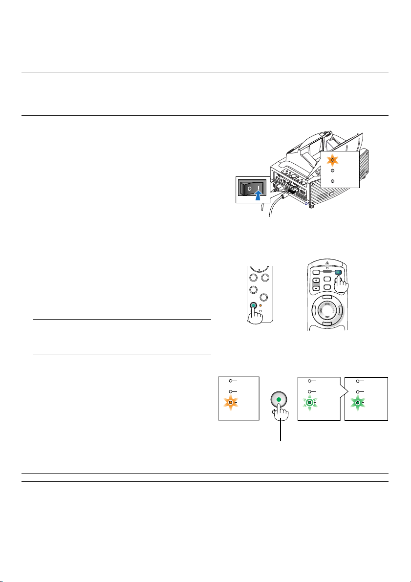
Level
Stands Suited
•Use a stand that will allow this projector to be set up in a level condition. Adjust the feet of the
stand to make sure it is level.
Recommended
Recommended
•In using this projector, increasing the screen size will move the projection position upward.To
accommodate this, please use a stand that has a height positioning adjustment. See page E-
2 for information about the positioning relationships between the screen and this projector.