nekos KATO SYNCRO User manual
“ DECLARATION OF CONFORMITY ”
I, the undersigned, representative of the company nekos s.r.l., declares that the product
defined below complies with the following directives:
89/336/EEC Directive
(EMC Directive)
and subsequent amendments
and that all the following standards have been applied:
EN 55014-1; EN 61000-2-3; EN 61000-3-3; EN 55014-2.
Last two figures of the year of the CE marking: ‘04
KATO
chain operated actuator 230V o 24V
Mason Vicentino, 1.03.2004
Giuliano Galliazzo
The President
nekos s.r.l. - italy
36064 mason vicentino (vi) _ via capitoni, 7/5
tel. 0424.411011 _ fax 0424.411013 _ www.nekos.it
english
instruction manual - Montage und Betriebsanleitung
Syncro

32
CONTENTS
1. SAFETY INDICATIONS page 4
2. USE OF KATO SYNCRO page 5
3. ACCESSORIES page 5
4. ELECTRICAL SUPPLY page 5
5. ASSEMBLY page 6
6. ELECTRICAL CONNECTIONS page 10
7. LUMINOUS INDICATIONS ON LED page 11
8. PROGRAMMING THE LIMIT SWITCHES page 11
9. TECHNICAL DATA page 13
10. CHECKING FOR CORRECT ASSEMBLY page 13
11. EMERGENCY MANOEUVRES, MAINTENANCE AND CLEANING page 14
12. TROUBLESHOOTING page 14
13. WARRANTY AND ENVIRONMENTAL PROTECTION page 14
14. FORCE CALCULATION FORMULAS page 15
DECLARATION OF CONFORMITY page 28
nekos products are specially manufactured in safe materials
in compliance with the requirements of legislation in force.
When correctly mounted, installed and used in accordance
with the present instructions, our products constitute no
danger to people, animals or property.
Products subject to EU directives comply with the essential
requirements stipulated by the latter.
CE markings mean that our products can be sold and installed
throughout the European Union without any further formality.
The CE mark on our products, packaging and user manuals
provided with the product, indicate
“presumed in conformity
with directives”
issued by the EU.
nekos holds the technical file with all the documentation to
show that our products have all been inspected to ensure
compliance with directives conformity.

GB
5
GB
4
1. SAFETY INDICATIONS
ATTENTION: PLEASE READ THE FOLLOWING SAFETY INDICATIONS CAREFULLY BEFORE ATTEMPTING
INSTALLATION OF THIS APPLIANCE. THESE INDICATIONS WILL HELP TO AVOID CONTACT WITH
ELECTRICAL CURRENT, INJURY AND OTHER ACCIDENTS. PLEASE KEEP THIS MANUAL FOR FUTURE
CONSULTATION.
Series KATO chain operated actuator has been designed exclusively for moving out-
ward opening windows, transom windows, centre-hung opening window sashes, small
domes and dormer windows. Any use of the actuator for applications other than those
indicated must previously be authorized by the manufacturer upon technical verification
of the application.
• The device must only be installed by competent and qualified technical staff.
• After removing all packaging, please verify that all parts of the appliance are present.
• Any plastic bags, polystyrene, or small metallic parts such as nails, clips, etc. must be
stored out of the reach of children as they constitute potential sources of danger.
• Before connecting the appliance to the electricity supply, check that the electricity
supply in use has the same characteristics as those indicated on the technical data
label on the device.
• This appliance is destined exclusively for the use for which it has been designed and
the manufacture cannot be held responsible for any damages incurred by improper
use.
• The chain operated actuator has been designed for the exclusive purpose of internal
installation. The manufacturer must be consulted for any other application.
• Installation of the device must be carried out in accordance with the instructions set
out by the manufacturer. Failure to follow these instructions could compromise safety.
•Warning: risk of injury in the event that the window should fall on outward opening
window frames. A safety system should be mounted onto the window to guard
against falls. This system should be able to withstand at least three times the total
weight of the window.
•Warning: Check that limit switch selection is less than at least one centimetre with
respect to the mechanical stops, limit switches or any eventual obstacles preventing
opening of the wing.
•Warning: this device may cause injury by crushing or dragging. During function,
when the actuator closes the frame, it applies a pressure force of 300N against the
ledge of the casing, and all due measures, care and attention should be taken to
avoid any crushing of fingers.
• Electricity supply installation must be carried out in accordance with regulations in
force.
• To ensure effective separation from the electricity grid, we suggest installation of a
temporary approved type bipolar switch
(push button)
. A multi-pole main switch with
minimum contact opening of 3 mm should be installed at the start of the command
line.
• Never clean the device with solvents or jets of water. Never immerse appliance in
water.
•Warning: in the event of damage or malfunction, switch off the device, disconnect
any electrical connections and request the intervention of a qualified technician.
• Eventual repairs must only be carried out by qualified staff at a service centre
authorized by the manufacturer.
• Always require exclusive use of original spare parts. Failure to comply with this
stipulation could compromise safety and forfeit warranty benefits for the device.
• In the event of trouble or doubts, please refer to your trust retailer or directly to
NEKOS S.r.l.
2. USE OF KATO SYNCRO
Kato Syncro chain actuator is provided with the new Nekos patented system for the
coordinated synchronization of chain movement. Electronic speed control is comple-
tely automatic and don’t need any external control unit; it is sufficient to connect
among them red and white cables already existent on feeding cable (see scheme on
page 11).
How to recognise it
To recognise on sight chain actuator Kato Syncro from other actuators of Kato series,
there are only three details:
• Label with Syncro mark attached near the one which reports actuator technical
data.
• Electrical feeding cable which is with 5 wires (3+2) for 230V a.c. version and with 4
wires (2+2) for 24V DC version.
• Dip-switch on actuator hip has four switches; normal actuator has only two and the
signalling led.
When it has to be mounted
Kato Syncro chain actuator is mounted when are necessary two attach points becau-
se window is particularly heavy or large and a single actuator doesn’t allow the per-
fect frame closure.
Please remind that force executed from a single actuator is the same as from an ana-
logue Kato actuator; so mounting two actuators the force applied on frame is double.
Frame movement occurs uniformly, synchronized and coordinated without interrup-
tions and/or speed variations of two actuators.
In case of one of the two actuators doesn’t run for any mechanical or electrical impe-
diment, the other stops too, guarantying in this way frame integrity.
3. ACCESSORIES
The KATO actuator is packed in one single carton. Each package contains:
• Actuator with 2 metres (±5%) lead, 2,5 metres for Kato Syncro.
• Standard support brackets with distancer (A).
• Bracket for vertical assembly of the actuator (B).
• Bracket for transom window (C).
• Bracket for outward opening fixture (D).
• Adhesive template for boring.
• Small parts packaging.
• Instruction manual.
4. ELECTRICITY SUPPLY
Depending on which model is used, the actuator can function on 24V=
(direct current)
,
with two cables in the lead, or on 230V~ (alternating current) 50 Hz with a three cable
lead.
For the low voltage version, a feeder with an outcoming tension correspondent to the
one indicated on the technical data label attached to the device and which transforms
GB
7
GB
6
supply mains voltage
(230V~ 50Hz or other)
in 24V D.C.
should be used. The feeder must have class II protection,
and correct functioning is guaranteed if a feeder type
approved or suggested by the manufacturer is used.
4.1. Section choice of supply cables
In low tension supply systems, tension falls due to cur-
rent passage in conductors is a basic aspect for safety
and good appliance function. It is therefore extremely
important that the conductor section in function of cable
length is calculated correctly.
The following table indicates cable lengths for an actua-
tor connected at nominal charge.
Cables section Actuator using
24V= 230V~
4,00 mm2~ 1.000 m ~ 3.000 m
2,50 mm2 ~ 750 m ~ 2,200 m
1,50 mm2 ~ 450 m ~ 1,350 m
0,75 mm2 ~ 160 m ~ 500 m
0,50 mm2~ 130 m ~ 400 m
5. ASSEMBLY
THESE INDICATIONS ARE INTENDED FOR THE ATTENTION OF
TECHNICIANS AND SPECIALIZED PERSONNEL. BASIC JOB
AND SAFETY TECHNIQUES ARE THEREFORE NOT INCLUDED.
All preparatory operations, assembly and electrical con-
nections must be carried out by technical and specialized
personnel to guarantee best performances and good fun-
ction of the KATO chain operated actuator.
First of all, please check that the following fundamental
points have been satisfied:
• Gear motor performances must be sufficient to move
the window; any limits indicated in the technical data
table on the product cannot be exceeded
(page 13)
. Any
eventual calculations may be made using the formula
on page 15 of this manual.
• Warning. Check that appliance has electrical feeding
type equal to the one provided by checking with the
data reported on the label attached to the gear motor.
The actuator with the 3 (three) cable lead functions on
230V~ (A.C.) 50/60Hz. The actuator with the 2 (two)
cable lead functions on 24V_ (D.C.) supplied either by
batteries or by means of the lead.
• Check that the actuator has not been damaged during
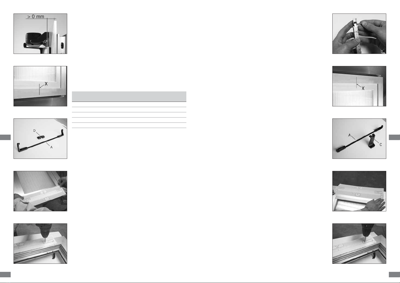
Fig. 1
Fig. 2
Fig. 3
Fig. 4
Fig. 5
transport, first visually and then by working it in both
directions.
• Check that the inner section of the window length
(where the actuator will be hung), is over 405 mm in
length. Anything shorter than this will not allow for
assembly of the actuator.
• Ensure that all load limits for the actuator are always
respected in accordance with the specifications listed in
the table on page 13. The actuator must be able to move
the blind without being hindered by any obstruction of
any kind; in the event of any obstruction, select a suita-
ble track run to avoid blockage.
• Check that once the actuator has been installed the
distance between the fixed part of the window frame
(where the actuator will be mounted)
and the moveable
part of the window frame
(where the bracket will be
mounted)
is more than 0 mm (Fig. 1). If the distance is
not more than this figure, the actuator will not be able
to complete its function, as the window will not be able
to close properly. A wedge should be placed under the
support brackets to redress the balance.
• Transom window frames entail the risk of injury cau-
sed by accidental fall of the window. A compass limit
switch or alternative safety system suitably designed
to prevent any accidental falls should be installed.
5.1. Assembly with outward opening window.
A. Pencil in an “X” over the centre line of the window
frame
(Fig. 2)
or divide the frame in 3 parts in case of
Kato Syncro mounting.
B. Select the correct form of brackets
(Fig. 3)
.
C. Attach the adhesive template to the window frame
(fixed part)
and line axis up with the centre line “X”
traced earlier
(Fig. 4)
. Warning: for window frames not
on the same plane, cut the part of the adhesive tem-
plate coloured in grey and fix this to the moveable
part of the window frame, taking care to keep it in the
same position.
D. Bore holes in the window frame at the points indicated
on the adhesive template
(Fig. 5)
.
E. Assemble the two brackets with the distancer
(to help
position correctly. Once it has served its purpose it
can be removed)
. Mount the supports onto the frame
with the appropriate screws provided. Check that eve-
rything is aligned both horizontally and vertically.
F. Mount the bracket for outward opening windows onto
the moveable part of the frame in accordance with the
markings indicated on the adhesive template.
G. Complete assembly of the chain terminal with the
Fig. 6
Fig. 7
Fig. 8
Fig. 9
Fig. 10

GB
9
GB
8
Fig. 11
Fig. 12
Fig. 13
Fig. 15
Fig. 14
rapid release hook inserted onto the pin Ø4x32
(provi-
ded)
in median position
(Fig. 6)
.
H. Mount the actuator onto the brackets by inserting the
two openings at each side onto the corresponding pins
on the brackets.
I. Rotate the actuator 90°, bring the chain terminal up
to the bracket and insert the pin into the opening on
the bracket. Insert the rapid release hook into the
bracket. For the first few times, this may fairly stiff, but
in time the pieces involved will adapt to their posi-
tions.
J. Check that the exit on the chain is perfectly aligned
with the bracket. If the chain is not aligned with the
bracket, loosen the fixing screws and reposition the
bracket correctly.
K. Check all electrical connections with the diagram on
the label attached to the lead.
L. Carry out a complete check of opening and closure of
the window. Once the closure phase has been comple-
ted, check that the window frame is completely closed
by checking the pressure on the weather strips.
M.On re-entry the actuator limit switch functions auto-
matically. The device exerts a traction force of over
300 N to guarantee perfect sealing up of the weather
strips.
5.2. Assembly on transom window.
A. Before starting, check that there are at least two
mechanical compass safety stops or other form of
stops connected to the frame, and ensure that the
stops can prevent any accidental fall of the window.
Your safety is at hand.
B. Pencil in an “X” over the centre line of the window
frame
(Fig. 7)
or divide the frame in 3 parts in case of
Kato Syncro mounting.
C. Select the correct form of brackets
(Fig. 8)
.
D. Attach the adhesive template to the window frame
(fixed part)
and line axis up with the centre line “X”
traced earlier
(Fig. 9)
. Warning: for window frames not
on the same plane, cut the part of the adhesive tem-
plate coloured in grey and fix this to the moveable
part of the window frame, taking care to keep it in the
same position.
E. Bore holes in the window frame at the points indicated
on the adhesive template
(Fig. 10)
.
F. Assemble the two brackets with the distancer
(to help
position correctly. Once it has served its purpose it
can be removed)
. Mount the supports onto the frame
with the appropriate screws provided. Check that eve-
rything is aligned both horizontally and vertically.
G. Mount the bracket for outward opening windows onto the moveable part of the
frame in accordance with the markings indicated on the adhesive template.
H. Complete assembly of the chain terminal with the rapid release hook inserted onto
the provided pin Ø4x32 in median position
(Fig. 11)
.
I. Mount the actuator onto the brackets by inserting the two openings at each side
onto the corresponding pins on the brackets.
J. Rotate the actuator 90°, bring the chain terminal up to the bracket and insert the
pin into the opening on the bracket. Insert the rapid release hook into the bracket.
K. Check that the exit on the chain is perfectly aligned with the bracket. If the chain is
not aligned with the bracket, loosen the fixing screws and reposition the bracket
correctly.
L. Check all electrical connections with the diagram on the label attached to the lead.
M.Carry out a complete check of opening and closure of the window. Once the closu-
re phase has been completed, check that the window frame is completely closed by
checking the pressure on the weather strips.
N. On re-entry the actuator limit switch functions automatically. The device exerts a
traction force of over 300 N to guarantee perfect sealing up of the weather strips.
5.3. Vertical assembly of the actuator on outward opening window.
A. Pencil in an “X” over the centre line of the window frame
(Fig. 12)
or divide the
frame in 3 parts in case of Kato Syncro mounting.
B. Select the correct form of brackets
(Fig. 13)
.
C. Fold the adhesive template along the green dotted line and keep in position at 90°.
Attach one part to the window frame
(fixed part)
, taking care to line up the axis with
the “X” previously pencilled in on the central line and line the folded part up against
the moveable part of the frame. Warning: as various different applications are pos-
sible, place the actuator in a central position and adjust the positions of the brac-
kets, taking care to keep the actuator aligned with the window section.
D. Bore holes into the window frame at the points indicated
(Fig. 14)
.
E. Mount the bracket for outward opening windows onto the moveable part of the
frame in accordance with the markings indicated on the adhesive template.
F. Complete assembly of the chain terminal with the rapid release hook inserted onto
the provided pin Ø4x32 in median position
(Fig. 15)
.
G. Mount the two brackets on to the sides of the actuator.
H. Position the actuator onto the window frame and line up with the holes bored ear-
lier. Fix the actuator in position with the screws provided.
I. Bring the chain terminal up to the bracket and insert the pin into the hole on the
bracket. Attach the rapid release hook to the bracket.
J. Check that the exit of the chain is perfectly aligned with the bracket. If the chain is
not aligned, loosen the fixing screws and reposition the bracket correctly.
K. Check all electrical connections with the diagram on the label attached to the lead.
L. Carry out a complete check of opening and closure of the window. Once the closu-
re phase has been completed, check that the window frame is completely closed by
checking the pressure on the weather strips.
M.On re-entry the actuator limit switch functions automatically. The device exerts a
traction force of over 300 N to guarantee perfect sealing up of the weather strips.
7. LUMINOUS INDICATIONS ON LED (only for Kato)
Before activating the actuator, familiarise yourself with messages indicated by the red
led opposite the lead. This will allow you to check that the machine is functioning pro-
perly or allow you to recognize possible irregularities.
The LED is only visible when the actuator has been turned on.
Status of LED Meaning
CONSTANTLY LIT MOTOR IN USE.
OFF AND FLASHING MOTOR HAS REGULARLY REACHED A LIMIT STOP BUT IS STILL
CONNECTED TO ELECTRICITY SUPPLY.
NORMAL REGULAR BLINKING MOTOR IN ELECTRONICAL PROTECTION DUE TO EXCESSIVE CHAR-
GE
ON AND FLASHING MOTOR IS IN STRANGE POSITION - MOTOR IS NO LONGER
PROGRAMMED.
8. PROGRAMMING THE LIMIT SWITCHES
8.1. Programming Kato actuator
Limit switches at opening
4
(four)
positions can be selected for the limit switch of the outgoing chain. To pro-
gram, adjust the two dip-switches at the side of the LED. Programming is simple,
immediate and can be carried out at any time by adjusting the two dip-switches as
indicated in the following table.
Limit switch at (mm): Dip-switch
1 - left 2 - right
110 OFF OFF
200 ON OFF
300 OFF ON
400 ON ON
After the limit switches have been programmed, run a few check manoeuvres. In the
event of error, programming can be repeated to give the desired track run.
GB
11
GB
10
6. ELECTRICAL CONNECTIONS
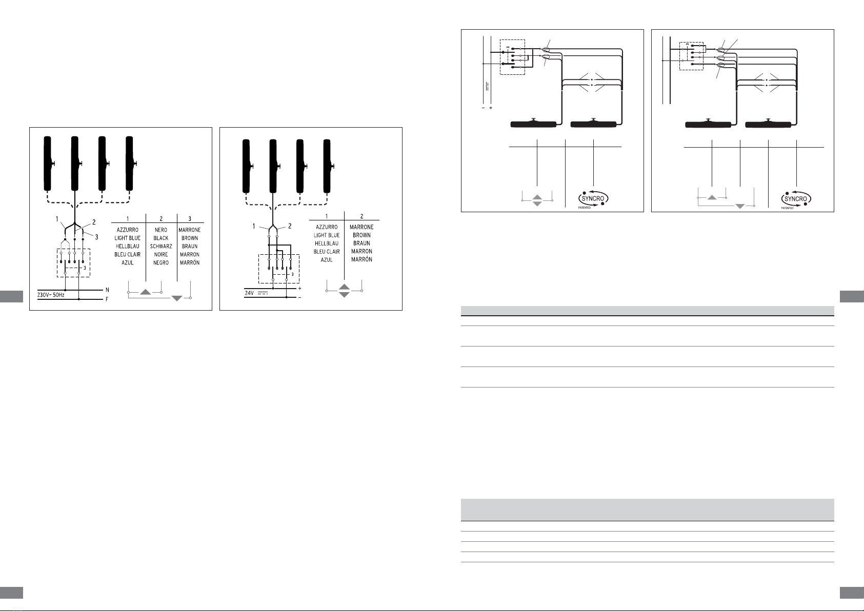
6.1. Connections of Kato.
The actuator comes with a 2 m long circa (±5%) lead which has been calculated in
accordance with safety rules. In the event that the distance between the actuator and
the control button should exceed this length, the cable should be extended. See table
on
page 6
for conductor section indications. For harness, please follow the following
diagrams.
After connecting the electricity supply to the control button
(bipolar with arrows if
possible)
, check that the up key function opens the window frame and the and down
key function closes it.
In the event that keys should function to the contrary, invert cable positions.
6.2. Connections of Kato Syncro.
Cable supplied together with actuator is 2,5 m (±5%) long and it is calculated in accor-
dance with safety rules.
In the event that the distances between the actuator and the control button should
exceed 2,5 metres, it would be possible to extend only conducers for electrical feeding.
See table on page 6 for conductor section indications.
WARNING. WHITE and RED cable can not be extended and have to be connected bet-
ween them on length equal or inferior than 2,5 m; an actuators distance higher than
5 metres doesn’t guarantee a good communication of synchronization signal.
Electrical connection of cables white and red has to be done with a loose connector of
proper dimensions (clamp is on equipment). Fundamental importance has a steady
connection, with a good electrical contact because passing tension is very low (5V).
IMPORTANT. CONNECTION OF TWO CABLES (WHITE AND RED) MUST BE DONE
BEFORE ANY OTHER MOVEMENT MANOEUVRE OF SYNCHRONIZED ACTUATORS,
WITH CHAINS COMPLETELY INSIDE; OTHERWISE COMMUNICATION PROBLEMS
COULD ARISE BETWEEN TWO ACTUATORS.
For harness, please follow these diagrams.
2
4
3
1
24V
1
AZZURRO
LIGHT BLUE
HELLBLAU
BLEU CLAIR
AZUL
2
MARRONE
BROWN
BRAUN
MARRON
MARRÓN
3
ROSSO
RED
ROT
ROUGE
ROJO
4
BIANCO
WHITE
WEISS
BLANC
BLANCO
FN
3
1
5
4
2
230V ~ 50Hz
1
AZZURRO
LIGHT BLUE
HELLBLAU
BLEU CLAIR
AZUL
2
NERO
BLACK
SCHWARZ
NOIRE
NEGRO
34
MARRONE
BROWN
BRAUN
MARRON
MARRÓN
ROSSO
RED
ROT
ROUGE
ROJO
BIANCO
WHITE
WEISS
BLANC
BLANCO
4

GB
13
GB
12
Limit switches at closure
The limit switch at closure is automatic, electronically operated and cannot be pro-
grammed. The actuator stops when the charge is absorbed when the window is com-
pletely closed and the weather stripping is completely depressed, or when the char-
ge absorbed is more than 10% of the nominal charge. In this case, at maximum char-
ge the actuator exercises a traction force of over 330N.
After each closure or intervention of the electrical protection mechanism, the chain
moves in the opposite direction for around 1 mm. This is to loosen the tension of the
mechanical parts and gives correct pressure to the weather stripping.
When the window frame is closed, check that the chain terminal is at least a couple of
millimetres away from the actuator body. This ensures proper closure for the window
and ensures all weather stripping is sealed. If the chain terminal is not positioned cor-
rectly there is no guarantee that the window will close completely.
Check that attachments and support brackets are firmly fixed to the window frame
and that all screws have been correctly tightened.
8.2. Programming Kato Syncro actuator
Limit switches at opening
4 (four) positions can be selected for the end stroke of the outgoing chain. To program,
properly adjust the two dip-switches no. 1 and no. 2.
Programming is simple, immediate and can be carried at any time by adjusting the two
dip-switches as indicated in the following table.
Limit switch at (mm): Dip-switch
no. 1 no. 2
100 OFF OFF
200 ON OFF
300 OFF ON
400 ON ON
After limit switches programming it’s advisable to run a few check manoeuvres. In the
event of error, programming can be repeated to give the desired truck run.
Limit switches at closure
(See specific chapter for KATO).
Programming for synchronized functioning
Two Kato Syncro actuators to run in a synchronized and coordinated way, have to be
programmed. Programming consists on determining actuator “MASTER” and the one
acting as “SLAVE”.
To do this it’s necessary to program dip-switches no. 3 and no. 4.
Actuator function Dip-switch
no. 3 no. 4
MASTER ON OFF
SLAVE OFF OFF
SINGLE ON ON
Programming repetition
In the event of actuators don’t run synchronized we suggest to neutralize and repeat
the programming acting in this way:
• Take the two actuators programming back to “SINGLE” function;
• Disconnect WHITE and RED wires;
• Act an outgoing movement for at least 100 mm;
• Make the chain income completely;
• Connect again WHITE and RED wires and do again the MASTER and SLAVE program-
ming.
Example of dip-switches programming for two actuators synchronized between them:
• Actuator no. 1 dip-switch no. 3 ON dip-switch no. 4 OFF
• Actuator no. 2 dip-switch no. 3 OFF dip-switch no. 4 OFF
9. TECHNICAL DATA
MODEL KATO - 230 KATO - 24
Pressure force 300 N
Traction force 300 N
Track runs
(can be selected at any time)
110, 200, 300, 400 mm
Voltage 230V~ 50 Hz 24V D.C.
Current consumption at nominal charge 0,115 A 0,880 A
Charge absorbed at nominal load ~ 28 W ~ 22 W
No load speed 14 mm/s 12 mm/s
No load duration
(400 mm)
25 s
Double electrical insulation YES Low voltage
Type of service S2di 3 min
Working temperature - 5 + 65 ºC
Protection index IP30
Adjustment of socket at casing Autopositioning
Connection of two or more devices in parallel YES
Limit switch stop at opening
Electronic with regulation by means of dip-switch
Limit switch stop at closure At absorption of charge
Dimensions mm 386,5x59x37
Weight 0,970 Kg 0,940 Kg
Any information reported in this table is not binding and may be susceptible to variations without notice.
10. CHECKING FOR CORRECT ASSEMBLY
• Check that the window has closed completely, even at the corners, and check there
are no obstacles caused by assembly in the wrong position.
• Check that when the window frame is closed, the chain terminal is at least a couple
of millimetres distant from the actuator body. This will ensure correct closure of the
window with correct pressure on the weather stripping. If the chain terminal is not
positioned as stated there is no guarantee the window will close correctly.
• Check that all attachments and support brackets are tightly fixed to the window
frame and that all screws are correctly tightened.
• Check that the window moves to the desired position in accordance with the limit
switch selected.
• Check that the gear motor support brackets are aligned and the four fixing screws
are firmly screwed into position.

GB
15
GB
14
11. EMERGENCY MANOEUVRES, MAINTENANCE AND CLEANING
Should the window have to be opened manually in the
event of no electricity, mechanical failure, or for normal
maintenance or cleaning of the external surface of the
window frame, the following instructions should be follo-
wed:
1. Release the rapid release hook locking the chain termi-
nal to the bracket.
2. Hold the window with one hand and pull the pin out of
the opening with the other hand
(Fig. 17)
.
3. Manually open the window.
12. TROUBLESHOOTING
Please consult the following table for any eventual problems with function during
installation or normal use:
Fig. 17
Problem
Gear motor doesn’t work
LED is lit but gear motor doesn’t
work.
Although selection has been car-
ried out correctly the gearmotor
will not take a limit switch.
Possible cause
• No electricity supply for feeder.
• Connecting cable not connec-
ted or wire not connected.
• Feeder doesn’t deliver foreseen
tension (24V).
• Switching feeder is damaged
and will not deliver low voltage.
• Gear motor is damaged due to
a shock. Motor connection has
unsoldered or has been discon-
nected.
• Programming hasn’t been car-
ried out correctly.
• Irregular function or break in
the electrical contact for the
dip-switch.
Solution
• Check state of safety switch.
• Check all electrical connections
of gear motor.
• Possible transformer winding
break down.
• Replace feeder
• Send gear motor to a Service
Centre.
• Repeat programming for dip-
switch.
• Send gear motor to a Service
Centre.
13. WARRANTY
The Manufacturer guarantees good machine function and undertakes to replace any
defective parts due to bad quality materials or construction defects.
This warranty covers products or their single parts for a period of 2 years from the
date of purchase. The warranty is valid if the buyer can present proof of purchase and
has satisfied any conditions of payment accorded.
The guarantee of good function of the device accorded by the manufacturer is
understood to cover the replacement and repair free of charge, in the shortest possible
period of time, of any eventual parts that should be damaged when under warranty.
The Buyer has no right to any compensation for possible damages, direct or indirect,
or other expenses. Any attempt at repair by unauthorised persons renders this warranty
null and void.
All fragile parts and those parts exposed to natural wear, as well as parts submitted to
agents or corrosive processes, temporary overload etc. are excluded from this
warranty. The Manufacturer will not accept responsibility for possible damages caused
by erroneous assembly, movement or insertion, use of excessive stress or improper use.
Any repairs carried out under warranty are always intended “Ex-factory producer”.
Relative transport expenses
(outgoing / return)
will be the responsibility of the Buyer.
13.1. ENVIRONMENTAL PROTECTION
All materials used in the manufacture of this appliance are recyclable. We recommend
that the device itself, and any accessories, packaging, etc. be sent to a centre for
ecological recycling.
14. FORMULAS TO CALCULATE FRAMES OPENING AND CLOSING FORCE
F = Force required to open and close
P = Window weight (only movable part)
C = Window opening truck run (actuator truck run)
A = Window height
For horizontal domes and
dormer windows
F = 0,54 x P
For outward opening (A) or
transom (B) windows
F = (0,54 x P) x (C : H)
Table of contents


