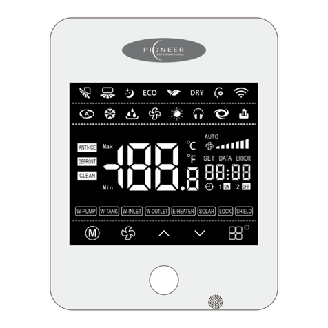
Pioneer BSG175A8R User manual

Product appearance depends on goods
Wired Controller
BSG175A8R
Thank you for choosing Pioneer International Air Conditioners, please read this owner’s
manual carefully before operation and retain it for future reference.
If you have lost the User's Manual,please contact the local agent or visit
www.pioneerair.com.au or sent email to [email protected]

Content
This marking indicates that this product should not be disposed with other household wastes
throughout the EU. To prevent possible harm to the environment or human health from
uncontrolled waste disposal, recycle it responsibly to promote the sustainable reuse of
material resources. To return your used device, please use the return and collection
systems or contact the retailer where the product was purchased. They can take this
product for environmental safe recycling.
User Instructions .................................................................................................... 1
Installation and Disassembly
..........................................................................
1
Installation Place and Installation Requirements ...................................................
1
Installation of the Signal Wire ................................................................................... 1
Installation of Wired Controller ................................................................................. 2
Disassembly the Wired Controller
...........................................................................
2
Display and Installation instruction
...........................................................
3
Liquid crystal display .................................................................................................. 3
Bottons ......................................................................................................................... 4
Operation Instruction .......................................................................................... 5
Lock Function .............................................................................................................. 5
The Switch of Centigrade and Fahrenheit
..............................................................
5
Defrost Function .......................................................................................................... 5
On/Off ........................................................................................................................... 5
Mode Setting ................................................................................................................ 5
Temperature Setting
..................................................................................................
5
Fan Speed Setting ...................................................................................................... 6
Swing Setting
..............................................................................................................
6
Timer Setting ............................................................................................................... 7
Turbo Function Setting ...............................................................................................8
Sleep Function Setting ............................................................................................... 8
Quiet Function Setting ............................................................................................... 9
Clean Reminder .......................................................................................................... 9
Master Indoor unit Setting ......................................................................................... 9
DRY Function Setting ................................................................................................. 9
ECO Function Setting .................................................................................................10
Error Code .................................................................................................................. 11
Wi-Fi Function .............................................................................................................. 5

1
User Instructions
Please carefully read this manual before installation and use of this
product.
●Do not install or remove the wired controller by yourself. If necessary, please contact
the after- sales serviceman.
●Do not install the wired controller in the humid area or under direct sunlight.
●Do not beat, toss, or frequently assemble/disassemble the wired controller.
●Do not operate the wired controller with wet hands.
●This wired controller is applicable to various kinds of air conditioners, while some
specific functions unavailable to the duct type air conditioners will not be covered in
this manual.
Installation and Disassembly
1.
Installation Place and Installation Requirements
●Do not install the wired controller in the humid area or under direct sunlight
●Do not install the wired controller close to the high-temperature object or place where
is easy to splash on the wired controller.
●Do not install the wired controller directly opposite to the window so as to avoid
improper operation caused by the interference of the neighbor’s same model wired
controller.
●Please cut off the power supply of wires embedded in the wall. No operation is
allowed with electricity.
●To avoid abnormal operation caused by electromagnetic interference or other causes,
please take notice of the following statements during wiring.
1.
Be sure the communication line is wired into the correct port, otherwise it would
lead to communication fault.
2.
The communication line (wired controller) and power line must be separated with
the minimal distance of 20cm, otherwise it would lead to communication fault.
3.
If the air conditioner is installed where is easy to suffer electromagnetic
interference, the communication line of the wired controller must be shielded
twisted pair.
2.
Installation of the Signal Wire
1.
Open the indoor unit electric box cover.
2.
Make the signal line go through the rubber band
3.
Insert the signal wire port in the 4-seat needle which on the indoor unit circuit board.
4. Tightly fix the signal wire with wire ties.
Notice:
The communication distance between main board and wired controller can reach 20m.
(The recommended length is 8m)

Installation and Disassembly
2
Installation and Disassembly
3. Installation of Wired Controller
The simple installation step of wired controller is as shown on the figure, please notice
below issues:
●Pull out the 4 core twisted pair wire from the mounting hole and pass this line
through the oblong hole located at the bottom of the wired controller.
●Use M4×25 screws to fix the base plate together with installation hole of the wall.
●Insert the through signal wire in the slot on the wired controller , also lock the wired
controller panel and base plate together.
Wired controller installation steps:
4. Disassembly the Wired Controller
1
2
1
2

Display and Installation instruction
3
Display and Installation instruction
Liquid crystal display
No.
Icon Name
Icon Instruction
1 Vertical Swing Vertical Swing function status
2 Horizontal Swing Horizontal Swing function status (N/A)
3 Sleep Sleep function status
4 ECO Energy saving function status
5 Dry Dry function status
6
Light Light of indoor unit display panel status;(not refer
to wired controller)
7 Memory Memory function status
8
Lock Keyboard lock status
9
Wi-FiWi-Fi function status
10
Auto Operating in AUTO mode
11
Cooling Operating in Cooling mode
Dehumidification Operating in Dehumidification mode
Fan Operating in Fan mode
Heating Operating in Heating mode
Quiet Quiet function status
16
Turbo Turbo function status
中间显示区域漏空
Max
Min
DEFROST
PM2.
5
GROUP
ADDR SET CHECK
ON
OFF
DAY HOUR
F - IR
TI-ICE
1 2 345 6 78 9
10 11 12 13 14 15 16 17 18
19 20 21 22 23 24 25 26 27
28
29 30
12
13
14
15

i
4
Buttons
N/A Low temperature heating function status
E-Heater E-Heater function status
Anti-ice Anti-ice function status
Defrost Defrost function status
Clean Refer to filter clean reminding
Fresh air Fresh air function status (N/A)
Group
Master Refer to master indoor unit
PM2.5 Refer to PM2.5 (N/A)
Shield Shield status (N/A)
TEMP. Ambient temp. / setting temp.
Fan speed Current setting fan speed
Timer Timer status
No.
Button Name
Button Instruction
1
Mode
2Fan
3 Increase Setting operating temp., range:20°C~25°C (68°F-77°F)
Setting timer time, range: 0.5-24 hour
4 Decrease
5 Function Select CLEAN, ECO, SLEEP, TURBO, QUIET, etc. functions
6 ON/OFF Turn on/off unit
1 3 5
246
17
18
19
20
21
22
23
24
25
26
27
28
29
30
Setting fan speed
Setting the operating mode:
Auto,Cooling,Dehumidication,Fan,Heating
Access control Plug-in/out card status (N/A)
Group function status (N/A)

Operation Instruction
5
Operation Installation
Lock Function
In the on/off-state, press " " and " " buttons at the same time for 5s till the wired
controller enters the lock state. In this case, the LED display " ". After that, repress
these two buttons at the same time for 5s to quit the lock state.
Notice:
In the lock state, if malfunction occur, all the buttons will be shield besides ON/OFF
button.
The Switch of Centigrade and Fahrenheit
In On/Off-state, press " " and " " button for 5s to switch between Centigrade
and Fahrenheit.
Defrost Function
In Heating mode, when the condition meets the standard that the outdoor unit control
system can turn on the defrost function, the units will defrost automatically, " "
icon appear.
On/Off
Press the " " button to turn on or off the unit.
Mode Setting
In on-state, press the " " button to switch the operation modes as the sequence
shown in below:
DEFROST
Heating
Cooling
Dehumidification
Wi-Fi Function
Press the " " and " " buttons for 3s into the Wi-Fi setting.
Temperature Setting
Press " " or " " button to increase or decrease setting temperature in on-state of
the unit. If press either of them continuously, temperature will be changed rapidly.
Temperature setting range is 20°C~25°C (68°F-77°F).

Operation Instruction
6
Operation Installation
Fan Speed Setting
Press " " button, fan speed of indoor unit will change as the sequence below:
Notice:
●After installation completed, wired controller will detect the unit type automatically.
Different types may have different ways of fan speed display, it can be divided into
the 2 kinds above.
●In Dehumidification mode, the fan speed is default to low fan speed and can not be
adjusted.
●When set the AUTO mode, the indoor fan speed will be changed according to the
indoor ambient temp., the fan speed strip is not displayed.
Swing Setting
In On-state,press" " button to access the function selection mode, press" " or "
" button to switch the swing function," " icon blinking,then press" " button
to access the swing position selection,press" " or " " button to adjust the
swing position,press" " button to turn on/off this function.
The swing function will be adjusted as below sequence:
OFF Auto Position1 Position2
Position3Position4Position5
No display
Notice:
In Auto mode, the setting temperature is un-adjustable.

Operation Instruction
7
Operation Installation
Timer Setting
In on-state, press " " button for 3s to set turn off time; in off-state,press " "
button for 3s to set turn on time. Timer range: 0.5-24h
Notice: The min gap of time display is 0.5h, less than 0.5h will display 0.5h.
●Timer Setting:
Press " " button, " SET" icon displayed, then press " " or " " to adjust the time,
after that, press the " " button again to make a confirmation ( " SET " disappeared),
setting complete.
●Cancel Timer Setting:
After Timer is set, press " " button, " SET " icon displayed ,then press " " button
for 3s, " SET " icon and timer time disappear, setting canceled.
Press " " button, "SET"
displayed
Press the " " button to
complete the setting
Press " "/" " to adjust
the time
Press " " button cancel
the timer setting
SET SET SET
SET

Operation Instruction
8
Operation Installation
Turbo Function Setting
In Cooling/Heating/Fan mode, press" " button for 3s to switch the Turbo function,
In this case,the LED display " " and " " .After that, press" " button at
the at the same time for 3s to quiet function. Then press" " button to turn off the
function.
Notice:
●When turn on Turbo function, the fan speed strip will not change.
●Switch to other mode and adjust the fan speed will both exit the Turbo function
automatically.
●Can not turn on "Turbo" and "Quiet" function in the same time.
●There has no Turbo function in Dehumidification/Auto mode.
Sleep Function Setting
In Cooling/Heating/Dehumidification mode, press " " button to access the
function selection mode, press " " or " " button to switch the Sleep function,
" "icon blinking, press " " button to turn on/off the function.
In Cooling/Heating/Fan mode Press " " bu tton switch to
the Turbo function
In Cooling/Heating/
Dehumidification mode
Press " " button switch to
the Sleep function, " " icon
blinking
Press the " " button to
turn on/off the function

9
Operation Installation
Quiet Function Setting
In Auto/Cooling/Dehumidification/Fan/Heating mode,press" "button for 3s to switch
the Turbo function,After that press" "button at the same time for 3s to Quiet
function ,In this case ,the LED display " "and " ".Then press " "button to turn
off the function.
Notice:
●When turn on Quiet function, the fan speed strip will not change.
●Switch to other mode and adjust the fan speed will both exit the Quiet function
automatically.
●Can not turn on "Turbo" and "Quiet" function at the same time.
Press " " bu tton switch to
the Quiet function
中间显 示 区域漏空
In Auto/Cooling/Dehumidification
Fan/Heating m ode
Clean Reminder
When the wired controller received Clean Reminder, " " icon blinking, press "
" to cancel the reminder
Master indoor unit setting
In on/off state of the unit,press" " and " " buttons for 5 seconds,then LED
display " F00",press " " button for 5 seconds ,LED display “A01”,then press " "
button,timer setting area blinking,adjust the value to "01"by pressing " " , " "
button,at last press " " button to make a confirm.
DRY function setting
In Cooling/Dehumidification mode, press " " button to access the function selection
mode, press" "or " "button to switch the DRY function," "icon blinking,then
press " " button to turn on/off this function.

Operation Instruction
10
Operation Installation
ECO Function Setting
ECO function can make the air conditioner runs in a smaller temperature range by
setting limited value of setting temperature in the Cooling or heating mode to achieve
energy saving.
In Cooling/Dehumidification/Heating mode, press " " button to access the function
selection mode, press" " or " " button to switch the ECO function," " icon
blinking, then press" " button to set cooling(heating) limited setting
temperature ,press " " / " " button to adjust the limited setting temperature, then
press " " button to turn on/off this function.
The initial min. limited cooling setting temperature is 25°C(77°F), the initial heating
max. limited heating setting temperature is 22°C(72°F).
In Cooling/Dehumidification
/Heating mode
Press " " button to access
the function selection mode
Press " " / " " button to
set cooling(heating) limited
setting temperature
Press " " button to turn
on/off this function

11
Error Code
When error happens to the unit, the error code will be
shown on the wired controller. When multiple errors
simultaneously happen, the error codes will circularly
show up.
When error occurs, please immediately shut down the
unit and contact service center.
●If show other code, please turn off and contact the
service center.
●If show "CL", please turn off and clean the
filter(please cut off power before take out filter).
Finish clean and well install the filter, please turn on , then the code will disappear.
Error Code Name
CL
H0
H1
H2
H3
H4
H5
H6
C8
C9
E0
E2
CJ
FF
C3
Cb
Filter clean remind
High exhaust temp. protection
Overcapacity protection
Compressor overload protection
Anti-frost protection
System high pressure protection
System low pressure protection
Lack refrigerant/ valve stop protection
Auxiliary heat adhesion protection
The communication between indoor unit and wired controller fault
Indoor temp. sensor open/short circuit
Outdoor temp. sensor open/short circuit
Wired controller temp. sensor fault
Defrost or heating oil return
Indoor unit report outdoor unit fault
Water full protection
CF
Eb
Refrigerant leakage failure
Gas sensor failure

Table of contents
Other Pioneer Controllers manuals

Pioneer
Pioneer DDJ-ERGO User manual

Pioneer
Pioneer SEP C1 - Software Entertainment Controller Assembly instructions

Pioneer
Pioneer KJR-12BP-F User manual

Pioneer
Pioneer AXM-P7650 User manual

Pioneer
Pioneer 9537EU User manual

Pioneer
Pioneer DDJ-ERGO-v User manual

Pioneer
Pioneer “Serato DJ” DDJ-ERGO User manual

Pioneer
Pioneer DDJ-SR User manual

Pioneer
Pioneer DDJ-ERGO-v User manual

Pioneer
Pioneer DDJ-ERGOlimited User manual