Nemco 6220-17 User manual

Model #s: 6220-17,
6220-28, 6225-17,
6225-28, 6230, 6235
6220-17
6220-28
6230
6225-17
6225-28
6235
Convection
Ovens

2
CONTENTS
TECHENICAL DATA Page. 3
INTRODUCTION Page. 11
Identifying the danger or warning signals
Purpose of the product
INSTALLATION Page. 11
Installation requirements
Transport
Unpacking
Installing the feet
Placement
Electrical connection
Water connection
Water drain
Conditioning the appliance
OPERATION INSTRUCTIONS Page. 15
Controls
General cooking information
CLEANING AND MAINTENANCE Page. 18
Outer stainless steel surfaces
Side supports
Air cover
Light bulb
Door gasket
Cooking chamber
External door glass
Internal door glass
TROUBLESHOOTING Page. 25
WIRING DIAGRAM Page. 26
EXPLODED DRAWINGS AND SPARE PARTS Page. 29
PRODUCT WARRANTY Page. 47
PRODUCT SERVICE Page. 47
TERMS & CONDITIONS Page. 47
3
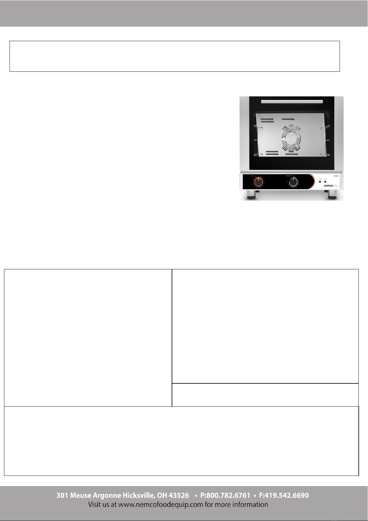
CAPACITY
(3) 18 in x 13 in / 460mm x 330mm half size pans
STANDARD EQUIPMENT
(2) 3-level side supports, 2.92 in (74 mm) step
FUNCTIONAL FEATURES
200°F to 500°F temperature range
Cooking timer up to 2 hours or run on infinite for continuous heat
Convection cooking
CONSTRUCTION FEATURES
Stainless steel constructed cooking chamber and shell
Glass door to facilitate cooking and cleaning operations
Recessed gasket to guarantee a sealed cooking chamber
6220-17, 6220-28 Technical Data
INSTALLATION REQUIREMENTS
The oven must be positioned on a level
surface
Hot surfaces must comply with the
minimum distance from the oven:
Left Side: 19.7 in (500mm)
Right Side: 19.7 in (500mm)
Rear Panel: 19.7 in (500mm)
Other surfaces must comply with the
minimum distances from the oven:
Left Side: 3.94 in (100mm)
Right Side: 3.94 in (100mm)
Rear Panel: 3.94 in (100mm)
SIZE SPECIFICATIONS
Weight without packaging: 61 lbs (27.7 kg)
Height without packaging: 21.06 in (535 mm)
Width without packaging: 23.62 in (600 mm)
Depth without packaging: 27.91 in (709 mm)
Weight with packaging: 71.2 lbs (32.3 kg)
Height with packaging: 23.62 in (600mm)
Width with packaging: 25.60 in (650mm)
Depth with packaging: 29.92 in (760mm)
OPERATION ELECTRICAL REQUIREMENTS
Voltage (V)
Amperage
(A)
PH
Hz
AWG
Connection
Watts (W)
Type of Plug
120
14.5
1
60
14
L1, L2/N, G
1700
NEMA 5-20
208
11,0
1
60
14
L1, L2/N, G
2650
NEMA 6-20
240
12,5
1
60
14
L1, L2/N, G
2800
NEMA 6-20
MAXIMUM LOAD PER PAN
3.5 lbs (1.5 kg)
4
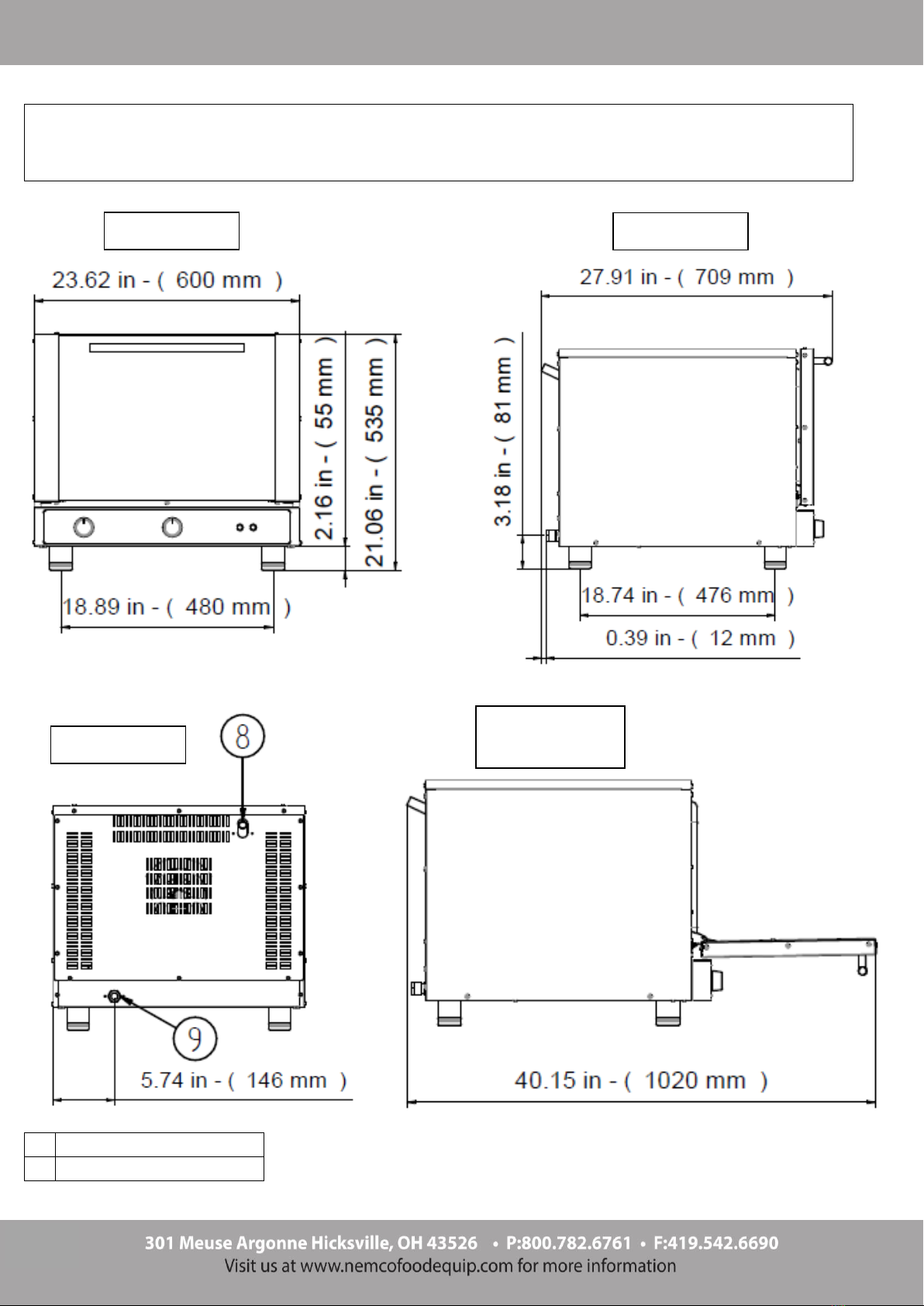
6220-17, 6220-28 Overall Dimensions
6
Water Inlet
8
Steam Exhaust Pipe
9
Power Cord Strain Relief
8
STEAM EXHAUST PIPE
9
POWER CORD STRAIN RELIEF
Front View
Side View
Rear View
Side View
Door Open

5
6230 Technical Data
CAPACITY
(3) 18 in x 13 in / 460mm x 330mm half size pan
STANDARD EQUIPMENT
(2) 3-level side supports, 2.92 in (74 mm) step
FUNCTIONAL FEATURES
200°F to 500°F temperature range
Cooking timer up to 2 hours or run on infinite for continuous heat
8 cooking modes available:
- Static upper and lower heat
- Static lower heat
- Static upper heat
- Static broil
- Convection broil
- Convection upper and lower heat
- Fan heat
- Fan only (for thawing/defrosting frozen products)
CONSTRUCTION FEATURES
Stainless steel constructed cooking chamber and shell
Glass door to facilitate cooking and cleaning operations
Reversing fan motor to guarantee cooking uniformity
Recessed gasket to guarantee a sealed cooking chamber
INSTALLATION REQUIREMENTS
The oven must be positioned on a level
surface
Hot surfaces must comply with the minimum
distance from the oven:
Left Side: 19.7 in (500mm)
Right Side: 19.7 in (500mm)
Rear Panel: 19.7 in (500mm)
Other surfaces must comply with the
minimum distances from the oven:
Left Side: 3.94 in (100mm)
Right Side: 3.94 in (100mm)
Rear Panel: 3.94 in (100mm)
SIZE SPECIFICATIONS
Weight without packaging: 95.7 lbs (43.4 kg)
Height without packaging: 25.82 in (656 mm)
Width without packaging: 23.62 in (600 mm)
Depth without packaging: 27.83 in (707 mm)
Weight with packaging: 106.7 lbs (48.4 kg)
Height with packaging: 23.62 in (600mm)
Width with packaging: 26.77 in (680mm)
Depth with packaging: 29.92 in (760mm)
OPERATION ELECTRICAL REQUIREMENTS
Voltage
(V)
Amperage
(A)
PH
Hz
AWG
Connection
Watts (W)
Type of Plug
208
11.5
1
60
12
L1, L2/N, G
2750
NEMA 6-20
240 13.0 1 60 12 L1, L2/N, G 2900 NEMA 6-20
MAXIMUM LOAD PER PAN
3.5 lbs (1.5 kg)
6
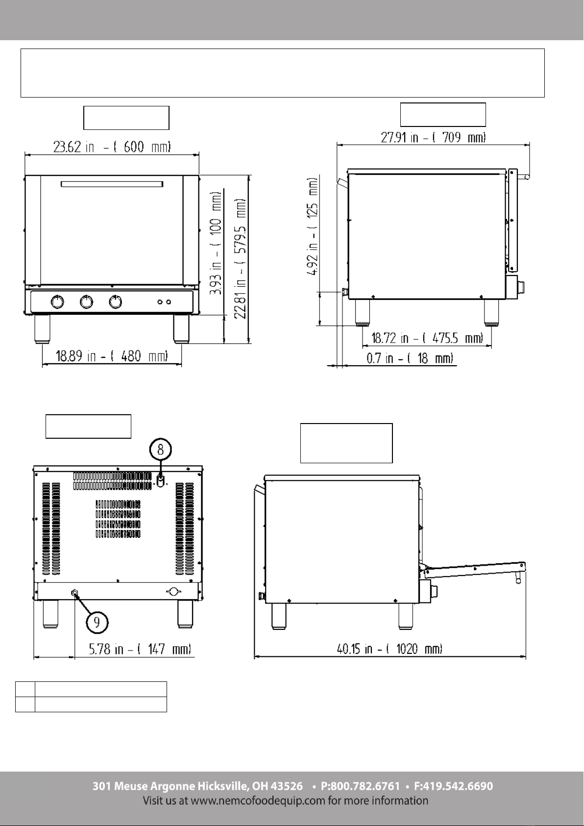
6230 Overall Dimensions
8
STEAM EXHAUST PIPE
9
POWE CORD STRAIN RELIEF
Front View
Side View
Rear View
Side View
Door Open

7
CAPACITY
(4) 18 in x 13in / 460mm x 330mm half size pan
STANDARD EQUIPMENT
4-level side supports, 2.92 in (74 mm) step.
FUNCTIONAL FEATURES
200°F to 500°F temperature range
Cooking timer up to 2 hours or run on infinite for continuous heat
Convection cooking
CONSTRUCTION FEATURES
Stainless steel constructed cooking chamber and shell
Inspection door to facilitate cooking and cleaning operations
Recessed gasket to guarantee a sealed cooking chamber
6225-17, 6225-28 Technical Data
INSTALLATION REQUIREMENTS
The oven must be positioned on a level
surface
Hot surfaces must comply with the
minimum distance from the oven:
Left Side: 19.7 in (500mm)
Right Side: 19.7 in (500mm)
Rear Panel: 19.7 in (500mm)
Other surfaces must comply with the
minimum distances from the oven:
Left Side: 3.94 in (100mm)
Right Side: 3.94 in (100mm)
Rear Panel: 3.94 in (100mm)
SIZE SPECIFICATIONS
Weight without packaging: 65.25 lbs (29.6 kg)
Height without packaging: 23.97 in (609 mm)
Width without packaging: 23.62 in (600 mm)
Depth without packaging: 27.91 in (709 mm)
Weight with packaging: 74.1 lbs (33.6 kg)
Height with packaging: 23.62 in (600mm)
Width with packaging: 25.60 in (650mm)
Depth with packaging: 29.92 in (760mm)
MAXIMUM LOAD PER PAN
3.5 lbs (1.5 kg)
OPERATION ELECTRICAL REQUIREMENTS
Voltage
(V)
Amperage
(A)
PH
Hz
AWG
Connection
Watts (W)
Type of Plug
120
14.5
1
50/60
14
L1, L2/N, G
1700
NEMA 5-20
208 11.0 1 50/60 12 L1, L2/N, G 2650 NEMA 6-20
240 12.5 1 50/60 12 L1, L2/N, G 2800 NEMA 6-20

8
6225-17, 6225-28 Overall Dimensions
8
STEAM EXHAUST PIPE
9
POWER CORD STRAIN RELIEF
Front View
Side View
Rear View
Side View
Door Open

9
6235 Technical Data
CAPACITY
(4) 18 in x 13 in / 460mm x 330mm half size pan
STANDARD EQUIPMENT
(2) 4-level side supports, 2.92 in (74 mm) step
FUNCTIONAL FEATURES
200°F to 500°F temperature range
Cooking timer up to 2 hours or run on infinite for continuous heat
2 cooking options available:
- convection cooking
- convection cooking with humidity
Manual humidity injection by pushing the steam button
CONSTRUCTION FEATURES
Stainless steel constructed cooking chamber and shell
Glass door to facilitate cooking and cleaning operations
Reversing fan motor to guarantee cooking uniformity
Recessed gasket to guarantee a sealed cooking chamber
INSTALLATION REQUIREMENTS
The oven must be positioned on a level
surface
Hot surfaces must comply with the
minimum distance from the oven:
Left Side: 19.7 in (500mm)
Right Side: 19.7 in (500mm)
Rear Panel: 19.7 in (500mm)
Other surfaces must comply with the
minimum distances from the oven:
Left Side: 3.94 in (100mm)
Right Side: 3.94 in (100mm)
Rear Panel: 3.94 in (100mm)
SIZE SPECIFICATIONS
Weight without packaging: 95.7 lbs (43.4 kg)
Height without packaging: 25.82 in (656 mm)
Width without packaging: 23.62 in (600 mm)
Depth without packaging: 27.83 in (707 mm)
Weight with packaging: 106.7 lbs (48.4 kg)
Height with packaging: 23.62 in (600mm)
Width with packaging: 26.77 in (680mm)
Depth with packaging: 29.92 in (760mm)
MAXIMUM LOAD PER PAN
3.5 lbs (1.5 kg)
OPERATION ELECTRICAL REQUIREMENTS
Voltage
(V)
Amperage
(A)
PH
Hz
AWG
Connection
Watts (W)
Type of Plug
208/240
11.5 / 13.0
1
60
12
L1, L2/N, G
2750 / 2900
NEMA 6-20
WATER QUALITY REQUIREMENTS
To guarantee correct operation of the appliance, the inlet water must be suitably treated in order to reach the requirements
below:
Without Chlorine Less than 0.1 ppm (mg/L)
Hardness 30-70 ppm
Chlorine Less than 30 ppm (mg/L)
pH From 7.0 to 8.5
Silica Less than 12 ppm (mg/L)
Total Dissolved Solids (TDS) 50-125 ppm
Failure to comply with these requirements may damage the appliance and/or its internal components.
The manufacturer is not liable for damage resulting from failure to comply with the water specifications above. Failure to
comply will void the warranty.

10
6235 Overall Dimensions
6
SOFTENED WATER INLET (THREADED ELECTROVALVE 3/4")
8
STEAM EXHAUST PIPE
9
POWER CORD STRAIN RELIEF
Side View
Rear View
Front View
Side View
Door Open
11
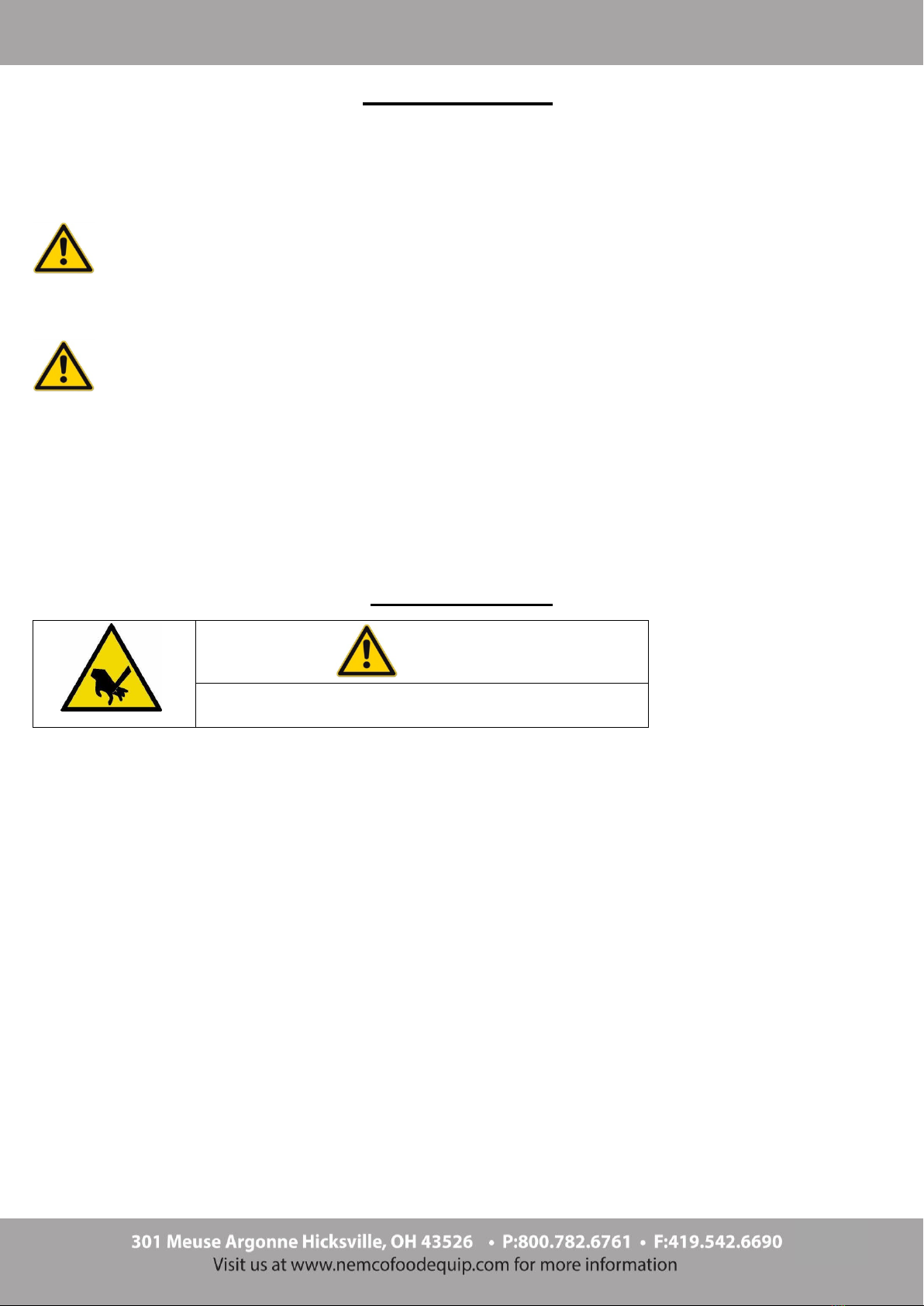
INTRODUCTION
Carefully read this user manual before using your new oven; pay special attention to the information highlighted
with the WARNING, CAUTION, and NOTES symbols
Identifying the danger or warning signals:
This signal indicates the presence of danger, which may cause serious injury, death, or damage if
disregarded.
This signal indicates the presence of danger, which may cause slight injury or damage if disregarded.
NOTES
Notes aim at indicating details or recommendations regarding installation, operation, or maintenance.
Notes contain important information, which is not related to possible risks.
This appliance has been specifically designed for food cooking. Any other use is considered improper.
INSTALLATION
Risk of injury.
Wear protective gloves during installation operations.
Installation requirements:
All installation and conditioning operations must be performed by a technically skilled installer, following
the manufacturer's instructions.
Comply with the instructions contained in this user manual. The manufacturer shall not be liable for
damage or harm to persons or property arising from installation errors. Nor are they responsible for any
appliance breakage caused by faulty installation.
Transport
During transport the appliance must be kept in its packaging in order to protect it from any external damage.
Unpacking
Remove the oven external packaging and make sure that the appliance has not been damaged during
transport. Inform the shipping company in the event damage is detected.
Remove any loose contents from the oven that are not intended for use during operation.
Carefully remove the plastic film that protects stainless steel components.
Remove any glue residue, which may result from removing the protective film, using a non-flammable
solvent.
CAUTION
WARNING
CAUTION

12
Installation of the feet
Risk of fire.
This appliance has been designed to operate with specific feet. Do not use the appliance without
installing the feet first.
Using the appliance without feet may cause fire due to overheating.
If the feet are not installed on the appliance, they are inside the cooking chamber and must be screwed into the
four threaded holes on the underside of the oven.
Placement
Place the appliance on a perfectly level work surface.
Should the appliance be installed near walls, shelves, or ceilings they must be of the non-flammable or
heat-insensitive type; otherwise, they must be protected by an adequate fire retardant coating.
NOTES
The appliance is unsuitable for recessing.
The following minimum distances from heat sources must be complied with to guarantee correct ventilation of the
appliance's electric component compartment:
Rear panel: 19.7 in / 500mm
Left side: 19.7 in / 500mm
Right side: 19.7 in / 500mm
And from near surfaces:
Rear panel: 3.94 in / 100mm
Left side: 3.94 in / 100mm
Right side: 3.94 in / 100mm
Do not obstruct the natural and/or forced ventilation openings on the appliance's exterior.
Do not obstruct the appliance's smoke/steam exhaust pipe.
Failure to comply with these notes WILL omit the manufacturer from any liability and will deem the
warranty invalid.
WARNING

13
Electrical Connection
NOTES
Before making the connections, make sure that the voltage and frequency of the power
supply system match the specifications of the "technical data" plate affixed to the
appliance.
The appliance must be connected to a suitable electrical system following the connection
data located on the sides of the machine.
If the power cord is damaged, it must be replaced by the manufacturer or a qualified service
technician.
If the oven is placed on a wheeled table, the connection conduit must be flexible. The table
wheels must be locked.
Appliances supplied with power cord already fitted:
Make sure that a suitable power cord and plug have been connected to the oven.
Appliances supplied without power cord:
NOTE Any electric connection must be made by qualified service technician.
Remove the appliance's rear/side panel (depending on the model) to access the terminal block.
Apply the conduit and allow enough wire to pass through to reach the terminal block.
Connect the hot legs to terminals “L1” & “L2” of the terminal board and the ground to the terminal with the
following symbol . Replace the appliance's rear/side panel once the operation is complete.
NOTES
The electrical system must be fitted with a pole circuit breaker with rated breaking current
equal to 150% of the current consumed by the appliance.
The circuit breaker must be installed near the appliance, but not behind it, and the operator
must be able to access it any time.
The circuit breaker must be clearly marked and easily accessible in case of fire.

14
Water Connection
The appliance MUST be hooked up to a softened water supply that meets the water specifications below. It is
necessary to use a softener, filter system, and/or reverse osmosis system to achieve this water purity and
limit the formation of lime scale inside the cooking chamber.
The water pressure must range between 14.5psi (100 kPa) and 29 psi (200 kPa).
If the pressure from the main water line exceeds 29psi (200 kpa), install a pressure reducer upstream of the
appliance.
If the value is lower than 14.5 psi (100 kpa) use a pump to raise the pressure. The water temperature must not
exceed 86°F (30°C).
Connection to the water mains must be performed through the ¾” threaded solenoid valve located at the rear
(bottom) of the appliance, interposing a mechanical filter and a stopcock (before connecting the filter drain off a
certain amount of water to flush the pipe from any dirt).
To guarantee the correct operation of the appliance, the inlet water must be suitably treated to reach the
requirements below:
Without chlorine Less than 0.1 ppm (mg/L)
Hardness 30-70 ppm
Chloride Less than 30 ppm (mg/L)
pH from 7.0 to 8.5
Silica Less than 12 ppm (mg/L)
Total dissolved solvents (TDS) 50-125 ppm
Failure to reach these specifications will damage the appliance and/or its internal components.
NOTE Any damage caused by limescale or other chemicals contained in the
water ARE NOT covered by warranty.
NOTE The equipment must be installed with adequate backflow protection to
comply with applicable federal, state, and local codes.
Conditioning the Appliance
Before the ovens first use it is recommended to run it with an empty cooking chamber for 60 minutes at a
temperature of 400°F. This will reduce the unpleasant, yet normal smells that come from heating the
insulation that is wrapped around the cooking chamber and the silicone used for external sealing are
dissipated.
Refer to the "Operation Instructions" section for any details on how to use the oven correctly.
15
OPERATION INSTRUCTIONS
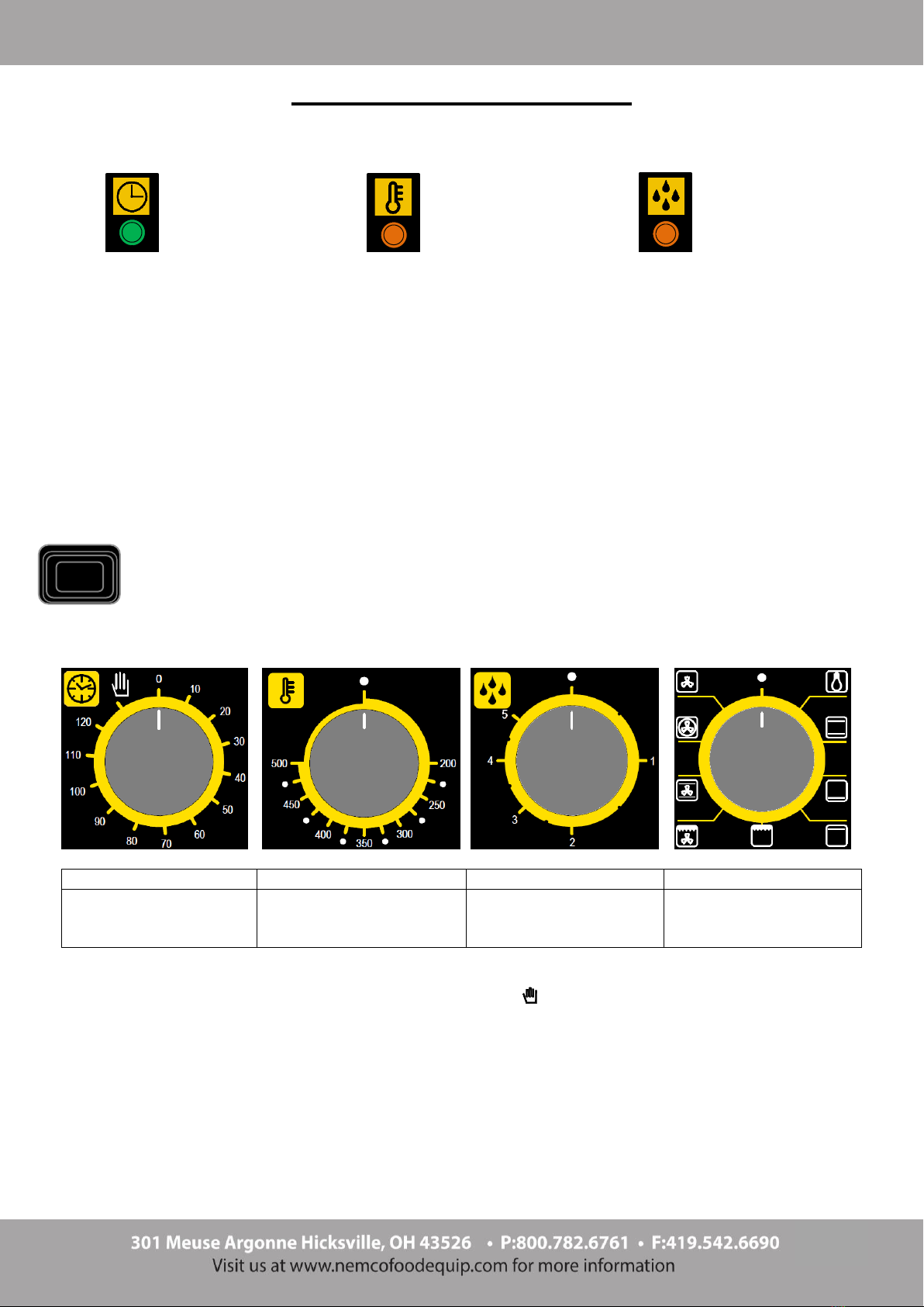
Control panels
Indicating lights
Program indicating light
It indicates that the oven is working and that cooking time may be active.
Heat indicating light
Switches off each time the set temperature is reached in the cooking chamber. It switches on again when the
thermostat is triggered to re-establish this temperature.
Automatic humidifier indicating light (for ovens with this option)
It indicates the water solenoid valve is open, hence humidity is being produced in the cooking chamber.
Switches / buttons
Control knobs
Fig. 1
Fig. 2
Fig. 3
Fig. 4
Timer Knob
Thermostat Knob
Automatic Humidifier
Knob
(For ovens with this option)
Function Selector Knob
(For ovens with this option)
Switching on/off
Switch on the oven by turning the Timer Knob (Fig. 1) to symbol or to the cooking time selected.
It is switched off by turning the knob to “zero”.
Setting the type of cooking
Turn the function selector knob (Fig. 4) to the type of cooking desired.
Cooking time setting
Turn the Timer Knob (Fig. 1) to the cooking time selected (up to 120 minutes). End of cooking is signaled with a
buzzer and the oven turning off.
Program indicating light
Heat indicating light
Automatic humidifier
indicating light
(for ovens with this option)
HUMIDIFICATION button
(For ovens with this option)
Press to intermittently create humidity

16
Cooking temperature setting
Turn the Thermostat Knob (Fig. 2) to the desired cooking temperature.
Humidity/steam amount setting
-Turn the Automatic Humidifier Knob (Fig. 3) to the desired humidity level (from 1 to 5). 1 being minimum
humidity and 5 being maximum. By turning the knob to “5” automatic humidifier control is disabled and steam
is generated continuously.
General Cooking Information
Ovens fitted with humidifier button:
"Convection" cooking
Switch on the oven and turn the thermostat knob to the desired temperature.
“Convection” cooking with humidity
Switch on the oven and turn the thermostat knob to at least 300°F. When this temperature value has stabilized,
press the humidification button to increase humidity in the cooking chamber.
Ovens fitted with automatic humidifier
"Convection" cooking
Switch on the oven and turn the thermostat knob to the desired temperature.
“Convection” cooking + humidity
Switch on the oven, turn the thermostat knob to the desired temperature, and turn the automatic humidifier knob
to the desired humidity level.
Ovens fitted with function selector:
“Traditional” cooking
Turn the function selector knob to the symbol and then turn the thermostat knob to the desired temperature.
To achieve differentiated cooking at the top or bottom, turn the function selector knob to the symbol for
bottom heat or the symbol for top heat.
Broiling
Turn the function selector knob to the symbol and then the thermostat knob to the desired temperature
(“Broiling” must be performed with the oven door closed).
Broiling with ventilation
Turn the function selector knob to the symbol and then the thermostat knob to the desired temperature
(“Ventilated broiling must be performed with the oven door closed).).
Baking with ventilation
Turn the function selector knob to the symbol and then the thermostat knob to the desired temperature.
Convection cooking
Turn the function selector knob to the symbol and that of the regulation thermostat to the required
temperature.

17
Defrosting
Turn the function selector knob to the symbol and then the thermostat knob to “off”.
Cooking suggestions
Convection cooking
Heat is transmitted to food through pre-heated air, which is forcefully circulated in the cooking chamber. The heat
reaches every part of the chamber evenly and quickly, to simultaneously cook different types of food arranged on
several shelves (as long as their cooking temperature is the same), without mixing flavor and smells. Convection
cooking is especially useful for rapid defrost, sterilizing bottled food, and drying fruits/vegetables.
Broiling
Almost all meats may be broiled, with the exception of some lean game and meat loafs. Meat and fish to be
broiled must be slightly greased with a little oil and always placed on the rack, arranged on the closest or farthest
rails depending on the type of meat in order to avoid burning it on the outside and not cooking it properly inside.
It is reccomended to place a tray underneath the grill to collect juice and fat drippings.
Broiling with ventilation
The thermal radiation produced by the grill is combined with forced air circulation to allow heat to gradually
penetrate food without burning its surface.

18
CLEANING AND MAINTENANCE
Risk of electrocution.
Disconnect the appliance's power supply before performing cleaning and maintenance operations.
The oven is not waterproof.
Do not submerge in water, spray with water jets, or steam to clean the inside or outside of the oven.
NOTES
Clean regularly and thoroughly.
DO NOT use abrasive cleaning pads or detergents that may damage the oven. Use specified
products only.
At the end of every cleaning operation, make sure that any material used has been fully removed.
If faults are detected, refer to the Troubleshooting guide (p. 25) and immediately perform
maintenance to solve the issue. Do not wait for the component to fully break.
Adapt the oven cleaning frequency based on its use.
Before cleaning the appliance, allow it to cool down to room temperature.
Complete Cleaning Instructions
Outer stainless steel surfaces
The outer steel surfaces must be cleaned with a cloth soaked in warm soapy water or mixed with a small amount
of vinegar. Once cleaned completely the surfaces must be rinsed using a cloth soaked in only warm water and
then dried with a dry soft cloth. If using other chemical products, make sure they do not contain abrasive, acid, or
corrosive substances. The counter supporting the appliance and/or the floor surrounding the appliance area
should also be cleaned using the same methods. Using the chemicals mentioned may corrode and deteriorate
the outer stainless steel shell and cause non-reparable damage to the electrical components inside the appliance.
Risk of injury.
Wear protective gloves during maintenance and cleaning operations.
WARNING
CAUTION
CAUTION
19
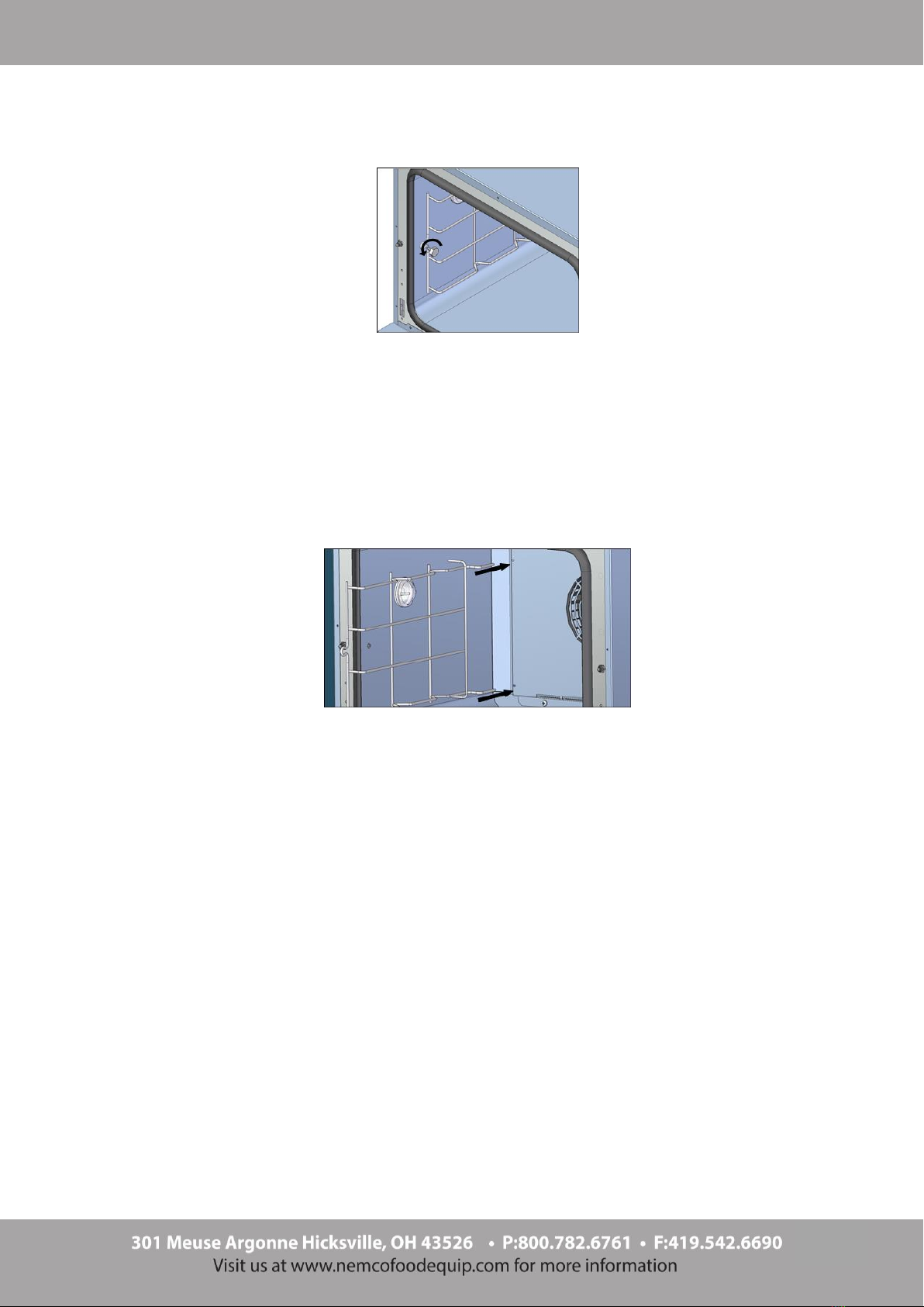
Side supports
1) Loosen the (2) hex head bolts (turn counter-clockwise) that fasten the side support to the cooking chamber.
2) Pull the side supports towards the door to remove them from the air cover panel.
3) Remove the side supports from inside the oven and clean them with a mild detergent and hot water, using a
soft bristle brush.
4) Carefully dry the side supports with a dry cloth.
5) Insert the side supports back into their positions on the oven air panel.
6) Fasten the side supports to the oven's cooking chamber using the (2) hex head bolts previously removed.
20
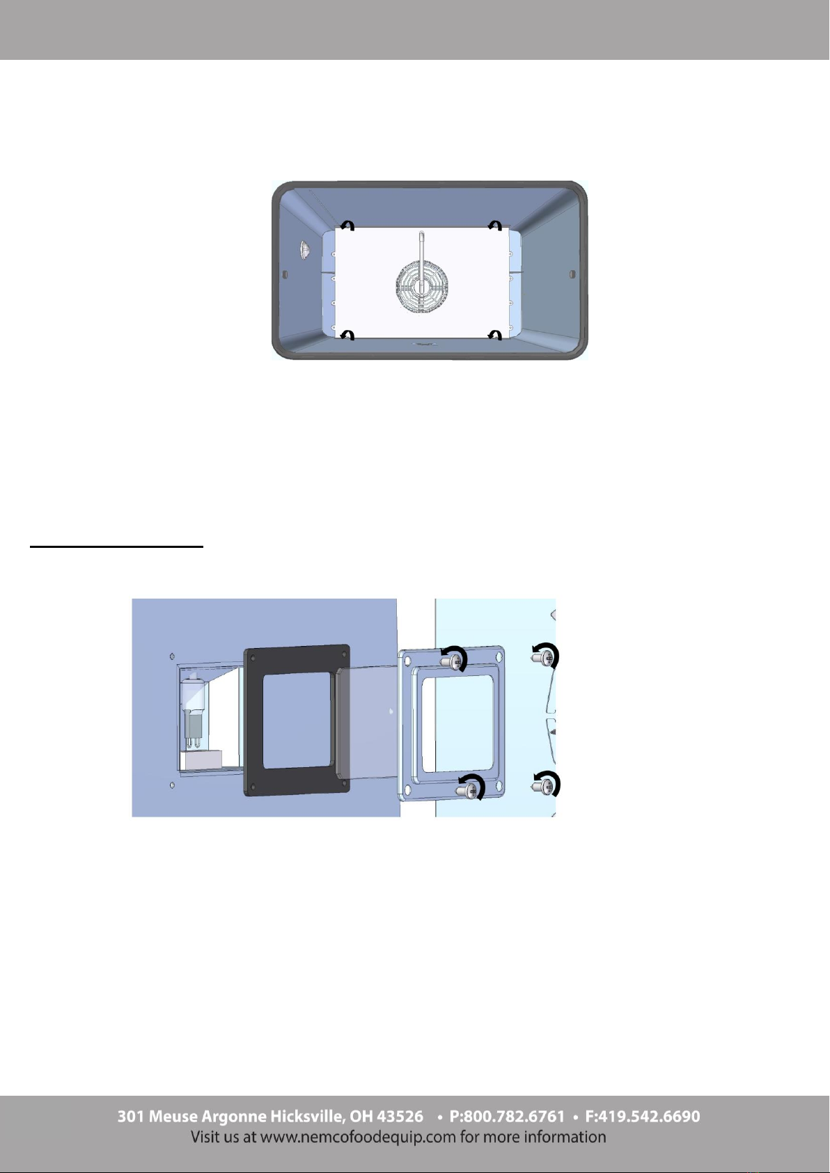
Air cover
1) Remove the side supports from the cooking chamber, following the “Side Supports“ instructions provided.
2) Remove the (4) screws that fasten the air cover to the cooking chamber.
3) Remove the air cover from inside the oven and clean it with a mild detergent and hot water, using a soft
bristle brush.
4) Carefully dry the air cover with a dry cloth.
5) Fasten the air cover to the oven's cooking chamber using (4) the screws previously removed.
Replacing the light bulb
For ovens with square light bulb covers
1) Remove the side supports from the cooking chamber, following the indications provided.
2) Unscrew the screws that secure the glass support and the relative seal.
3) Use a dry cloth to remove the light bulb from its socket and replace it with an exact match.
4) Reassemble the glass support and its gasket.
Other manuals for 6220-17
1
This manual suits for next models
5
Table of contents
Other Nemco Convection Oven manuals


