Nemo's Living Objects Frizzi User manual
Frizzi
®
OFF
A122 cm
13cm
22 cm
CB
AVVERTENZE GENERALI
∞ Prima di procedere al montaggio, all’installazione e
al collegamento elettrico del ventilatore, leggete
attentamente queste istruzioni. Accertatevi che i
datitecnici riportati nella targhetta sulla calotta pla-
stica trasparente di copertura delle parti elettroni-
che corrispondano a quelli della rete di distribuzio-
ne elettrica del vostro ambiente (fig. A).
∞ Il collegamento elettrico deve essere eseguito in
conformità alle norme CEI 64-9 e in presenza di un
impianto dotato di messa a terra, e solo se la porta-
ta dell’impianto/presa è adeguata alla sua potenza
massima.
∞ L’apparecchio deve essere collegato alla rete di ali-
mentazione tramite un interruttore onnipolare che
abbia una distanza di 3mm tra i contatti.
∞Durante il montaggio, assicuratevi dell’integrità di
tutti i componenti contenuti nell’imballo e se trova-
ste qualche elemento danneggiato, contattate
Nemo S.p.A.
∞ Ilventilatore dovrà essere destinatosolo all’usoper
il quale è stato espressamente progettato ecioèper
muovere l’aria e, nella versione con luce, illuminare
l’ambiente. Nemo S.p.A. non può essere considera-
ta responsabile per eventuali danni derivati da uso
improprio, erroneo o irrazionale.
∞ Ogni modifica apportata all’attacco predisposto,
farà decadere la garanzia e solleverà Nemo S.p.A.
da eventuali responsabilità. Il ventilatore è destina-
to adessere utilizzato a temperatura ambiente non
superiore a 40°C (104F°)
∞ L’installazione deve essere effettuata secondoque-
ste istruzioni da personale professionalmente qua-
lificato. L’errata installazione può causare danni a
persone, animali o cose e Nemo S.p.A. non può
essere considerata responsabile.
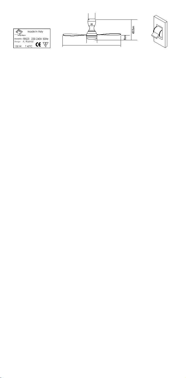
∞ Il ventilatore deve essere fissato a un’altezza non
inferiore a 2,30 metri dal suolo al punto più basso
del ventilatore, facendo attenzione chenon vi siano
ostacoli tra il fascio infrarossi del telecomando e la
finestra con i led. Mantenete una giusta distanza
dalle pareti circostanti tenendo in considerazione
l’ampiezza delle pale (fig. B).
∞ Se durante l’installazione il ventilatore dovesse
cadere o inavvertitamente ricevere dei colpi, fatelo
verificare da Nemo S.p.A.
∞ Prima di procedere al collegamento elettrico, assi-
curatevidi aver interrotto la tensione di rete (fig. C).
∞Osservate alcuneregolefondamentali:nontoccate-
lo con mani bagnate o nude, non collegatelo rima-
nendo a piedi nudi, non fatelo toccare da bambini o
persone di evidente incapacità. Inoltre fate atten-
zione a non lasciare il ventilatore esposto ad agenti
atmosferici o a sostanze infiammabili come benzi-
na, alcool, insetticidi.
∞ In caso di guasto o cattivo funzionamento spegnete il
ventilatore e non intervenite. Per la riparazione rivol-
getevi a personale professionalmente qualificato e
richiedetel’usodei ricambi originali Nemo S.p.A.
GENERAL WARNING
∞ Priorto beginning assembly, installation and electri-
cal wiring of the air fan, read carefully these direc-
tions for use. Make certain that the technical data
shown on the plate built-in the transparent hood,
covering the electronic components (fig. A), match
with the ratingof the electrical system in your flat.
∞ Electrical wiring should be, in compliance with CEI
Rules 64-9, for an electric system provided with
grounding prop, and only if the plug socket rating is
adequate to match the maximum load of the
appliance.
∞ During the assembly, make certain that all compo-
nents in the package are safe and sound. In case
componentsare found damaged, contact the manu-
facturing Company: Nemo S.p.A.
∞ The appliance shall be wired to the supply system
by means of an omnipolar switch featuring a mini-
mum gap between the contact surfaces.
∞ The fan shall be usedonly for the purpose for which
it was designed, i.e. to move air in the interior, and,
in the model mounting light bulbs, to illuminate the
ambient. Nemo S.p.A. may not be considered
responsible for any damage resulting from impro-
per, wrong or irrational use ofthe air fan.
∞ Every and any change made to the preset plug cou-
pling will cause the cancellation of the warranty,
thus Nemo S.p.A. will be released from any liability.
The air fan is designed for use in a room where the
temperature does not exceed 40°C (104°F).
∞ The installation shall be made by skilled and quali-
fied personnel, in accordance with these instruc-
tions. A wrongly performed installation can have
injuries to people, animals or damages to thingsas
consequence, for which Nemo S.p.A. may not be
heldresponsible.
∞ The air fan shall be secured in the lowestpositionat
a height not less than 2,30m above the floor, and
great care must be taken to check that no obstacles
are lying between the infrared ray beam from the
remote control and the Led window. Keep a proper
distance to the surrounding walls, for which the
width of blades is to be taken into consideration
(Fig. B).
∞ Ifduringthe installationtheair fanshould fall onthe
ground or receive hits, let it be inspected by Nemo
S.p.A.for damages.
∞ Before making electrical wiring, make certain the
voltagefromthemainshasbeen switchedoff(fig.C).
∞ Comply with some fundamental rules: do not touch
theairfanwithbareorwethands,norwithbarefeet,
and never let children or unskilled persons have
contact with the fan. Take care that the air fan is not
leftexposed to weathering agents, norto inflamma-
ble substances such asgasoline, alcoholand insec-
ticides.
∞ In case ofa failureor irregularfunctioning of the fan,
switch off the power to itimmediately, and never try
to make any repair yourself. For repairs, apply to
skilled and professionally qualified personnel only,
and use exclusively original spare parts bearing
Nemo’s Trade Mark.
INSTRUCTIONS GÉNÉRALES
∞ Avantde procéder aumontage, à l'installation et au
branchement électrique du ventilateur, lire attenti-
vement les présentes instructions. S'assurer que
les caractéristiques techniques reportéessur la pla-
que signalétique apposée sur la calotte en plasti-
que transparent qui couvre les parties électroni-
ques correspondent à celles du réseau de distribu-
tion électrique de votre environnement(fig.A).
∞ Le branchement électrique doit être effectué
conformément aux normes CEI 64-9, sur une instal-
lationmunie d'unemiseà la terre,et seulementsi le
débitde l'installation/priseest adaptéàsapuissan-
ce maximale.
∞L'appareil doit être branchéau secteur à l'aide d'un
interrupteur omnipolaire présentant une distance
de 3 mm entre les contacts.
∞ Pendant les opérations de montage, contrôler
l'intégrité de tous les composants présents dans
l'emballe; si un quelconque élément est endom-
magé, contacterNemo S.p.A.
∞ Utiliserleventilateur uniquementpour l'usagepour
lequel ila été expressément conçu, à savoir lacircu-
lation de l'airet,dans la versionavec ampoule, pour
l'éclairage del'environnement.Nemo S.p.A. ne sau-
rait assumer aucune responsabilité pour les dom-
mageséventuels causés par suite d'un usage inap-

proprié, erroné ou irrationnel dece produit.
∞ Toute modification effectuée à la prise annulera la
garantie et dégagera Nemo S.p.A. de toute éven-
tuelle responsabilité. Ce ventilateur est prévu pour
être utilisé à une température ambiante non supé-
rieure à 40°C (104°F).
∞ L'installation doit être effectuée en respectant les
présentesinstructionsparunpersonnelprofession-
nellement qualifié. En cas d'installation incorrecte,
NemoS.p.A. nepourra être tenue pourresponsable
des lésions ou dommages provoqués aux person-
nes, animaux ou choses.
∞ Le ventilateur doit être fixé à une hauteur non infé-
rieure à 2,30 m du sol au point le plus bas du venti-
lateur, en faisant attention à ce qu'il n'y ait aucun
obstacle entre le faisceau de rayons infrarouges de
la télécommande et de la fenêtre avec les diodes.
Laisser une distance suffisante par rapport aux
mursenvironnantsentenantcompte del'envergure
des pales(fig. B).
∞ Encas dechuteduventilateurou decoups subispar
celui-ci lors de son installation, il est nécessaire de
le faire contrôler par Nemo S.p.A.
∞ Avantdeprocéderaubranchementélectrique,vérifier
d'avoir coupé l'alimentation électrique au secteur
(fig. C).
∞ Respecterquelquesrèglesfondamentales:nepastou-
cher l'appareil avec les mains mouillées ou à mains
nues, ne pas le brancheren étant pieds nus et empê-
cher que des enfants ou des personnes inaptes ne le
touchent. Ne pas exposer le ventilateur aux agents
atmosphériqueouàdessubstancesinflammables tel-
les quel'essence,l'alcool ou lesinsecticides.
∞ En cas de panne ou de dysfonctionnement, arrêter
le ventilateur et ne pasessayerdele réparer.Pour sa
réparation, s'adresser à un personnel profession-
nellement qualifié et demander à ce qu'il soit uni-
quement fait usage de pièces détachées originales
Nemo S.p.A.
ALLGEMEINE HINWEISE
∞ Vor der Montage, der Installation und dem elektri-
schen Anschluß des Ventilators müssen die vorlie-
genden Anleitungen genau durchgelesen werden.
Vergewissern Sie sich, daß die auf der Plakette auf
der transparenten Kunststoffkalotte der elektroni-
schen Baugruppen angegebenen Kenndaten den
Kenndaten Ihres Stromnetzesentsprechen(Abb. A).
∞ Der elektrische Anschluß muß entsprechend der
Bestimmungen CEI 64-9 an ein geerdetes Netz mit
einem der maximalen Leistung des Ventilators ent-
sprechenden Stromdurchsatz ausgeführt werden.
∞ Das Gerät muß über einen mehrpoligen
Einausschalter mit Mindestabstand zwischen den
Kontakten von 3 mm an das Stromnetz angeschlos-
sen werden.
∞ Vergewissern Sie sich vor der Installation, daß alle
in der Verpackung enthaltenen Teile unversehrt
sind; wenden Sie sich an die Fa. Nemo S.p.A., falls
Sie beschädigte Komponenten antreffen sollten.
∞ Der Ventilator darf nur für den spezifisch vorge-
sehen Zweck, d.h. zur Umwälzung der Raumluft
bzw., in der Ausführung mit Beleuchtung, zur
Luftumwälzung und Raumausleuchtung eingesetzt
werden. Die Fa. Nemo S.p.A. haftet nicht im Fall von
Schäden, welche aufeinen unsachgemäßen, unvor-
schriftsmäßigen oder unvernünftigen Einsatz des
Geräts zurückzuführen wären.
∞ Jede Art der Modifikation des Anschlußstückes
beinhaltet den Verfall der Herstellergarantie und
befreitdieFa.Nemo S.p.A. vongleichwelcherHaftung.
DerVentilatordarfnurinRäumenmitTemperaturnicht
über 40°C(104 F°) eingesetztwerden.
∞ Die Installation des Geräts muß gemäß der vorlie-
genden Anleitungen erfolgen und darf nur von qua-
lifizierten Fachkräften ausgeführt werden. Eine
nicht vorschriftsmäßige Installation kann zu
Verletzungen von Personen und Tieren sowie zur
Beschädigung von Gegenständen führen und
befreit die Fa. Nemo S.p.A. in diesem Falle von jeder
Art der Haftung.
∞ Der Ventilator muß in einer Höhe nicht unter 2,3 m
vom Boden (gemessen von der tiefsten Stelle des
Ventilators aus) installiert werden; achten Sie
darauf, daß im Raum keine Gegenstände präsent
sind, die die Infrarotstrahlen zwischen der
Fernsteuerung und dem LED-Fenster des
Ventilators unterbrechen könnten. Achten Sie des
weiteren darauf, daß ein der Länge der Flügel des
Ventilators angemessener Abstand zu allen
Wändendes Raums gewährleistet ist (Abb. B).
∞ Lassen Sie den Ventilator von der Fa. Nemo S.p.A.
kontrollieren, falls er im Zuge der Installation zu
Bodenstürzen oder Stößenausgesetzt wordensein
sollte.
∞ Vergewissern Sie sich vor Ausführung des elektri-
schen Anschlusses, daß die Netzstromversorgung
unterbrochen wurde(Abb. C).
∞ Beachten Sie folgende Grundregeln: Den Ventilator
nicht mit nassen oder feuchten Händen anfassen;
während des elektrischen Anschlusses
Sicherheitsschuhe tragen; den Ventilator aus der
Reichweite von Kindern und Personen mit einge-
schränkter geistiger Fähigkeit bringen; den
Ventilator nicht wetterbedingten Einwirkungen
oder leicht entflammbaren Stoffen wie Benzin,
Alkohol oder Präparaten zur Insektenbekämpfung
aussetzen.
∞ Bei Störungen oder Nichtfunktion den Ventilator
ausschalten und keine eigenmächtigen Eingriffe
ausführen. Wenden Sie sich zur Ausführung von
Reparaturen nuran qualifizierteFachkräfte und ver-
langen Sie nach Original Nemo S.p.A.-Ersatzteilen.
ADVERTENCIAS GENERALES
∞ Antes de comenzar el montaje, la instalación y la
conexión eléctrica del ventilador, lean atentamente
estasinstrucciones.Cerciorarseque losdatostécni-
cos en la placa de la tapa de plástico transparente
de cobertura de las partes electrónicas correspon-
dan a los de la red de distribución eléctrica de su
ambiente (fig. A).
∞ La conexión eléctrica debe ser efectuada respetan-
do las normas CEI 64-9 y ante la presencia de una
instalaciónconpuesta atierra,ysólosi lacapacidad
de la instalación / toma es adecuada a su potencia
máxima.
∞ El dispositivo debe estar conectado a la red de ali-
mentaciónpor mediodeuninterruptoromnipolarque
tengaunadistancia de 3mm.entre los contactos.
∞Durante elmontaje,controlar la integridadde todos
los componentes contenidos en el embalaje y si
detectase algún elemento arruinado, pónganse en
contacto con Nemo S.p.A.
∞ El ventilador se deberá destinar solamente para el
uso para el que fue proyectado, vale decir, mover el
aire, y en la versión con luz, iluminar el ambiente.
Nemo S.p.A. no puede ser considerada responsa-
blepor eventuales daños quederiven deusoimpro-
pio, erróneo o irracional.
∞ Con modificaciones aportadasen la conexiónpredi-
spuesta, decaerá la garantía y eximirá a Nemo
S.p.A. de eventuales responsabilidades. El ventila-
dor debe ser usado en temperaturas ambientales
que no superen los 40°C (104° F).
∞ La instalación será efectuada de acuerdo con estas
instrucciones por personas especializadas. La
instalación errada puede causar daños a personas,
animaleso cosas, por lo que Nemo S.p.A. no puede
ser considerada responsable.
∞ El ventilador debe estar fijado aunaalturanoinferior
a 2.30m delsuelocon respectoalpunto másbajo del
ventilador, sin obstáculos entre el haz de infrarrojos
del controlremoto yla ventanaconlos led. Mantener
unajustadistanciade las paredescircunstantes con-
siderandola amplitud delaspalas (fig. B).
∞ Sidurante lainstalaciónel ventiladorcayese o inad-
vertidamente recibiese golpes someterlo alcontrol
de Nemo S.p.A.
∞ Antes de la conexióneléctrica, controlarla interrup-
ción de la tensión en la red (fig. C).
∞ Respetenalgunasreglas fundamentales:notocarlo
con las manos mojadas o desnudas, no conectarlo
descalzo, no permitir que lo toquen niños o perso-
nasconevidenteincapacidad.Asimismo,evitarque
el ventilador permanezca expuesto a los agentes
atmosféricos o a sustancias inflamables como
gasolina, alcohol, insecticidas.
∞ Encasodeaveríaomalfuncionamientoapagarelven-
tiladorynointervengan.Encuantoalareparacióndiri-
girse a personal profesionalmente especializado y
pidan el uso de repuestosoriginales NemoS.p.A.

MONTAGGIO
Prima di procedere al montaggio, assicuratevi di aver scollegato la
tensione di rete (fig. 1 ).
Per assemblare agevolmente il ventilatore, appoggiatelo su una
superficie solida e non abrasiva: vi consigliamo ad esempio di seder-
vi e di trattenerlo tra le ginocchia, in modo da controllarlo in sicurezza
(fig. 2)
Montate le pale una alla volta inserendole nella fenditura
(fig. 3-4), serrando bene le quattro viti della staffa di bloccaggio con la
chiave a brugola in dotazione (fig. 5).
Fissatel’anellometallico stringendo bene letreviti utilizzando lachia-
ve a brugola in dotazione (fig. 6).
ASSEMBLY
Before starting to assemble, make certain that power system has
been set in OFF position (fig.1).
To make assembly easy, place the air fan on a solid and not abrasive
surface:wesuggestforinstance you are sitting on achairandhold the
fan clamped firmly between your knees, so that you can have a control
over it in full safety (fig.2).
Install the fan blades, one after the other, by letting them slide into the
slot provided (fig.3-4). Tighten up the four mounting screws at the
lock bracket using the socket head spanner from the tool outfit (fig.5).
By tightening full up the three screws, secure the metal ring. Use for it
the socket head spanner from the tool outfit (fig.6).
MONTAGE
Avant de procéder aux opérations de montage du ventilateur, s'assu-
rer d'avoir mis l'appareil hors tension (fig. 1).
Pour assembler facilement le ventilateur, le poser sur une surface sta-
ble et non abrasive; il est recommandé par exemple de s'asseoir et de
le poser sur ses genoux afin d'avoir un contrôle sûr (fig. 2).
Installer les pales une par une en les insérant dans la fente (fig. 3-4);
serrer fermement les quatre vis de la bride de blocage à l'aide de la clé
mâle coudée fournie (fig. 5).
Fixer l'anneau métallique et serrer fermement les trois vis en utilisant
la clé mâle coudée fournie (fig. 6).
MONTAGE
Vergewissern Sie sich vor der Montage, daß die Netzstromversorgung
unterbrochen wurde (Abb. 1).
Setzen Sie den Ventilator zur Vereinfachung des Zusammenbaus auf
eine robuste, nicht scheuernde Fläche. Es wird geraten, denVentilator
während des Zusammenbaus im Sitzen zwischen den Knien festzuk-
lemmen (Abb. 2).
Montieren Sie die Flügel nacheinander, indem Sie sie in den dafür vor-
gesehenen Schlitzeinführen (Abb.3 -4);ziehen Sie die 4Schraubendes
Haltebügels mit dem mitgelieferten Inbusschlüssel gut fest (Abb. 5).
Befestigen Sie den Metallring, indem Sie die 3 Schrauben mit dem
mitgelieferten Inbusschlüssel gut festziehen (Abb. 6).
MONTAJE
Antes de comenzar el montaje, controlar la desconexión de la tensión
de red (fig. 1). Para armar cómodamente el ventilador, apóyenlo sobre
una superficie sólida y no abrasiva: les sugerimos permanecer senta-
dos y retenerlo entre las rodillas, de modo que puedan controlarlo en
seguridad (fig. 2).
Monten las palas una por vez introduciéndolas en la ranura (fig. 3 – 4),
apretando bien los cuatro tornillos de la abrazadera de bloqueo con la
llave de cabeza hexagonal entregada (fig. 5).
Fijenelanillo metálico apretando bienlostres tornillos usando lallave
de cabeza hexagonal entregada (fig. 6).
1
2
3
4
5
6
OFF
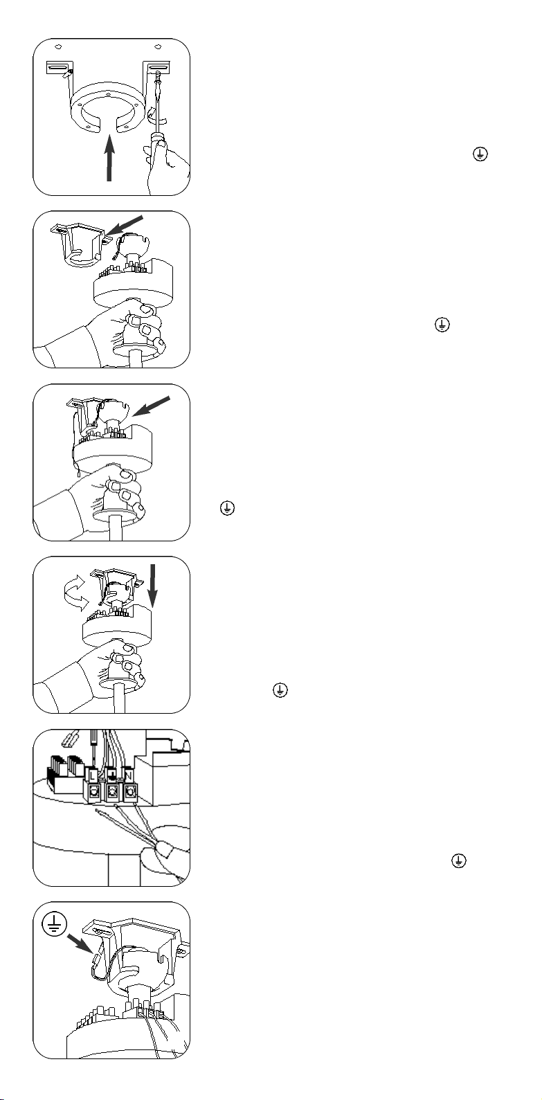
INSTALLAZIONE
Montate la staffa al plafone (soffitto) fissandola con due viti adeguate
a sostenere il peso del ventilatore ~7,5 Kg (fig. 7).
Appendete il ventilatore alla staffa inserendolo dalla parte aperta
facendo corrispondere la gola presente sullo snodo (A) con il dente
della staffa B (fig. 8-9) e tirandolo con cura verso il basso affinché si
disponga correttamente nella sede (fig. 10).
COLLEGAMENTO ELETTRICO
Procedete con il collegamento elettrico: collegate i cavi L-N e
al morsetto (fig. 11), e il faston del cavo di terra fissato alla staffa
(fig. 12).
INSTALLATION
Secure the bracket to the ceiling by means of two screws of a size sui-
table to carry a the dead weight of the air fan ~ 7,5 kg (fig.7). Hang the
air fan onto the bracket by inserting it into the free space available. Let
the slot on the knuckle joint (A) coincide with in the tooth in the
bracket B (fig.8-9), then and pull it carefully down, so that it can com-
bine correctly into the seat provided there (fig.10).
ELECTRICALWIRING
Carry out the electrical wiring: wire cables L-N and lead to the
earth the clamp (fig.11), and have the fast-on contact of ground wire
secured to the bracket (fig.12).
INSTALLATION
Fixer l'étrier au plafond à l'aide de deux vis capables de soutenir le
ventilateur qui pèse environ 7,5 kg (fig. 7).
Accrocher le ventilateur à l'étrier en l'introduisant par la partie ouver-
te et en alignant la gorge présente sur l'articulation (A) à la dent de l'é-
trier B (fig. 8-9) puis tirer avec soin vers le bas jusqu'à ce qu'il soit cor-
rectement positionné dans son logement (fig. 10).
BRANCHEMENTÉLECTRIQUE
Procédure pour le branchement électrique: connecter les câbles L-N
et à la borne (fig. 11) et le faston du câble de terre à l'étrier (fig. 12)
INSTALLATION
Bringen Sie den Haltebügel an der Decke an, indem Sie ihn mit zwei
dem Gewicht des Ventilators entsprechenden Dübelschrauben (~7,5
Kg) befestigen (Abb. 7).
Bringen Sie denVentilator am Haltebügel an, indem Sie ihn vom offe-
nenBereichaus einführen;achtenSie dabeidarauf,daß dieKerbedes
Gelenks (A) an den Zapfen des Haltebügels (B) gesetzt wird (Abb. 8 -
9), und drücken Sie den Ventilator vorsichtig so weit nach, bis er
genau in den Sitz gebracht wird (Abb. 10).
ELEKTRISCHER ANSCHLUSS
Gehen Sie zum elektrischen Anschluß wie folgt vor: Schließen Sie die
Leiter L- N und an die Klemme (Abb. 11) und die Faston-Kupplung
des am Haltebügel angebrachten Erdleiters an (Abb. 12).
INSTALACIÓN
Monten la abrazadera en el cielorraso con dos tornillos adecuados a
sostener el peso del ventilador 7,5 Kg. ~ (fig. 7).
Cuelguen el ventilador en la abrazadera introduciéndolo de la parte
abierta, de modo que corresponda el brazo que está en la articulación
(A) con el diente de la abrazadera B (fig. 8 – 9) y tirándolo cuidadosa-
mente hacia abajo para que se disponga correctamente en el lugar
(fig. 10).
CONEXIÓN ELÉCTRICA
Efectuar la conexión eléctrica: conecten los cables L– N y al borne
(fig. 11), y el faston del cable de tierra fijado a la abrazadera (fig. 12).
7
8
A
B
9
10
11
12

Potete ora montare i due gusci plastici: avvicinare uno dei due gusci
(fig 13) in modo tale che le nervature interne si inseriscano nella sede
presente sulla plastica trasparente del coperchio copri elettronica. Se
correttamente inserito rimarrà in sede senza l’ausilio delle mani (fig.
14). Accostare il secondo guscio facendo corrispondere i dentini pla-
stici e fissarli con le quattro viti in dotazione (fig. 15).
Versione senza luce: avvicinate la calotta plastica, inserite il pomello
filettato ed avvitate (fig. 16).
Versione con luce: inserite le quattro lampade alogene senza toccar-
le con le mani nude. Vi consigliamo di non estrarle completamente
dalla singola bustina in modo da evitare il contatto (fig.17).
Avvicinate il diffusore in vetro, inserite la guarnizione di protezione
nel pomello filettato ed avvitate (fig. 17).
Now, you can assemble the two plastic material shells: approach one
the two shells (fig.13), in a way that its inner ribs can penetrate their
seats provided in the transparent plastic lead covering the electro-
nics. If inserted correctly, it will remain in its seat without need of
manual aid (fig.14). Approach the second shell having the plastic
teeth rightly coincident with their mating parts, and secure with the
four screws supplied (fig.15).
No-light bulb model: approach the plastic hood, insert the threaded
ball grip and screw-on (fig.16).
Light bulb-fitted model: fit the four halogen light bulbs in position
without touching them with your bare hands.We suggest to take the
bulbs not completely out from their individual enveloping bag, so that
a direct contact with the skin can be avoided (fig.17). Approach the
glass diffuser, fit protective gaskets into the threaded ball grip and
screw-on (fig.17).
Monter ensuite les deux coques en plastique: approcher l'une des
deux coques (fig. 13) de façon à ce que les nervures internes s'insè-
rent parfaitement sur le plastique transparent du couvercle protège-
électronique. Si elle est installée correctement, la coque restera dans
son emplacement sans aucun besoin de la tenir avec les mains (fig.
14). Approcher ensuite la deuxième coque en faisant coïncider parfai-
tement les dents en plastique avec les sièges prévus à cet effet. Fixer
ensuite les coques à l'aide des quatre vis fournies (fig. 15).
Version sans lumière: approcher la calotte en plastique, insérer le
bouton fileté et visser (fig. 16).
Version avec lumière: installer les quatre lampes halogènes sans les
toucher directement avec les doigts; il est conseillé de ne pas les sor-
tir complètement de leur sachet afin d'éviter tout contact (fig. 17).
Approcher le diffuseur en verre, installer le joint de protection dans le
bouton fileté et ensuite visser (fig. 17).
Montieren Sie nun die beiden Kunststoffgehäuse. Positionieren Sie
eines der beiden Gehäuse so, daß die inneren Riefelungen in den Sitz
in der transparenten Kunststoffkalotte zum Schutz der
Elektronikkomponenten gebracht werden (Abb. 13). Bei korrekter
Einführung bleibt die Kalotte ohne manuelle Eingriffe in ihrem Sitz
(Abb. 14). Positionieren Sie nun das zweite Gehäuse so, daß die
Kunststoffzapfen einander entsprechen, und blockieren Sie die
Kunststoffzapfen mit Hilfe der 4 zum Gerät gehörigen Schrauben
(Abb. 15).
Version ohne Licht: positionieren Sie die Kunststoffkalotte, setzen
Sie den Gewindeknauf ein und schrauben Sie fest (Abb. 16).
Version mit Licht: setzen Sie die 4 Halogenlampen ein, ohne sie mit
den Händen zu berühren. Um Berührungen zu vermeiden, raten wir,
die Halogenlampen nicht vollständig aus den Hüllen zu ziehen (Abb.
17). Positionieren Sie die Glasschale, setzen Sie die Dichtung zum
Schutz des Gewindeknaufs ein und schrauben Sie fest (Abb. 17).
Ahora pueden montar las dos cápsulas de plástico: acercar una de las
dos cápsulas (fig. 13) de modo que las nervaduras internas se pongan
en el lugar presente en el plástico transparente de la tapa que cubre
los componentes electrónicos. Si introducidos correctamente perma-
neceráenellugar sin el auxiliodelasmanos (fig. 14). Arrimarlasegun-
da cápsula de modo que los dientes de plástico correspondan y fijar-
los con los cuatro tornillos entregados (fig. 15).
Versión sin luz: acerquen la tapa de plástico, pongan el pomo con
rosca y atornillen (fig. 16).
Versión con luz:introduzcan las cuatro bombillas alógenas sin tocar-
las con las manos desnudas. Les sugerimos no quitarlas completa-
mente de los sobres para evitar el contacto (fig. 17). Acerquen el difu-
sor de vidrio, introduzcan la vaina de protección en el pomo con rosca
y atornillen (fig. 17).
13
14
15
16
PLASTIC
17
GLASS
GLASS
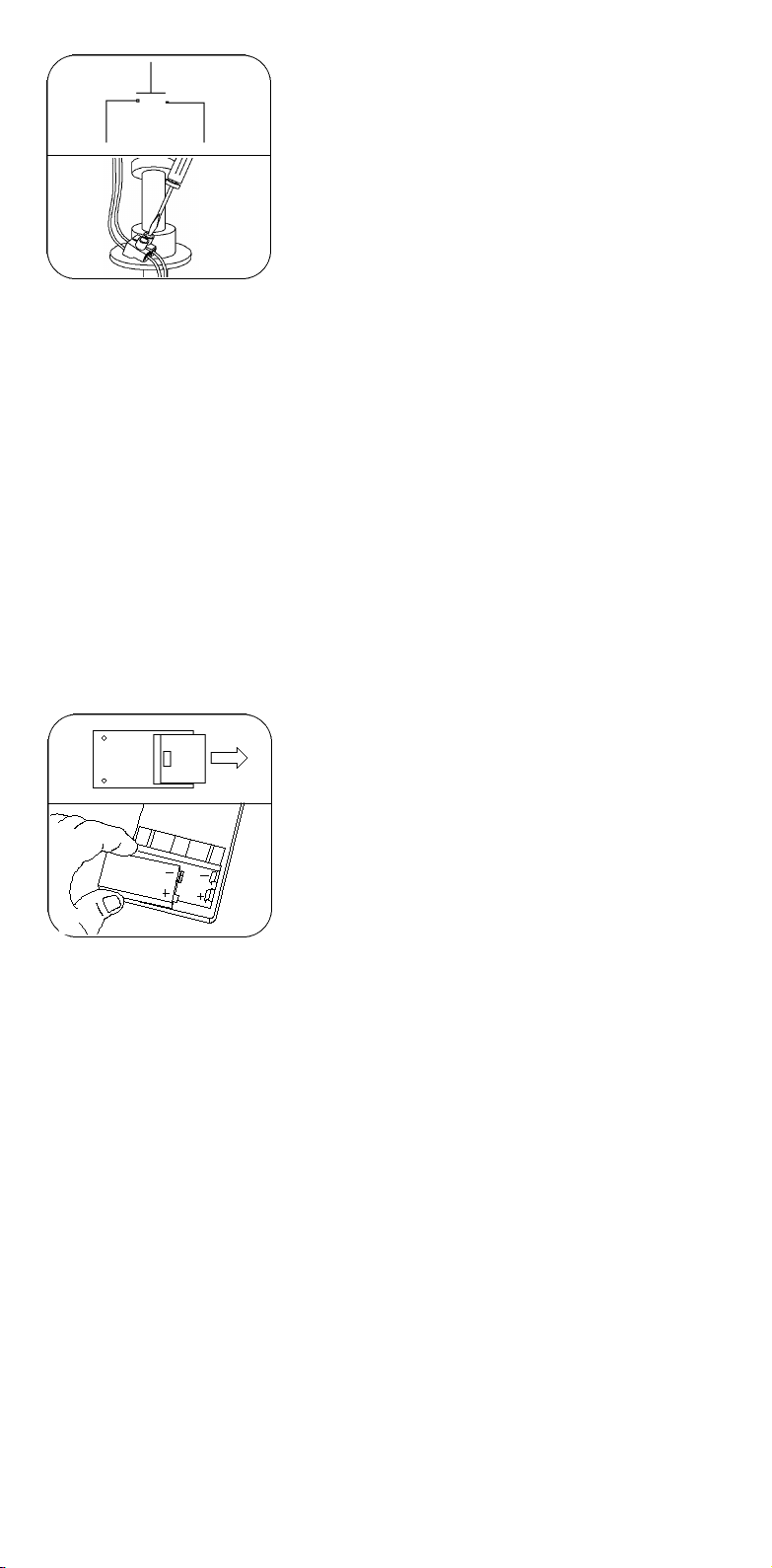
PER COMANDARE LE LUCI DA UN PULSANTE A PARETE
(SOLO PER LA VERSIONE CON LUCE)
Il ventilatore viene comandato dal telecomando alimentato a batteria
(9V size). Il ventilatore è predisposto per gestire il comando luci con
Pulsante Normalmente Aperto. Collegare i cavi provenienti dal pulsante
con icavi neri Ae B provenientidal ventilatore, assicurandosi che i cavidi
collegamentosianodi sezioneda 0,5a1,5mm esiutilizzi un pulsanteper
BassaTensione Normalmente Aperto. Schema elettrico (fig. 18).
TO CONTROLLIGHTS FROM A WALL-MOUNTED PUSH SWITCH
(FOR LIGHTBULB-FITTED MODELONLY)
The air fan control is over a cell-powered remote control (9V size), alka-
line type. The air fan is preset for a light control by N.O. contact push
switch. Branch the wires from the push switch to the black cover wires,
A and B, coming from the air fan. On doling it, make first certain that wiring cables measure 0,5 to 1,5 in cross-
section and use is being made of a LowVoltage Normally Open push switch. Electric Wiring Diagram (fig.18).
POURCOMMANDERL'ÉCLAIRAGEÀ L'AIDE D'UN INTERRUPTEURMURAL(SEULEMENTPOURLAVERSIONAVECAMPOULE)
Le ventilateur est muni d'une télécommande alimentée par une pile 9V. Le ventilateur est prévu pour gérer la
commande de l'éclairage lorsque l'Interrupteur est Normalement Ouvert. Brancher les câbles en provenance
de l'interrupteur avec les câbles noirs A et B en provenance du ventilateur, en vérifiant que les câbles de rac-
cordement ont une section comprise entre 0,5 et 1,5 mm et l'interrupteur utilisé est de type Basse Tension
Normalement Ouvert. Schéma électrique (fig. 18).
LICHTEINSCHALTUNG ÜBER WANDSCHALTER (NUR FÜR VERSION MIT LICHT)
DerVentilator wird über eine von einer Batterie (9V gespeiste) Fernsteuerung gesteuert. Dennoch kann das Licht
auch über einen Druckschaltermit Schließerkontakt ein – und ausgeschaltet werden. Schließen Sie die Leiter die-
ses Schalters an die schwarzenLeiter A und B desVentilators an; achten Sie dabei auf folgende Voraussetzungen:
dieVerbindungsleitermüssen einenQuerschnittzwischen0,5und 1,5 mm haben und esmußeinDruckschalter für
Niederspannung mit Schließerkontakt (NO) verwendet werden (siehe Schaltplan,Abb. 18).
PARA CONTROLAR LAS LUCES DESDE UN BOTÓN DE PARED (SÓLO PARA LAVERSIÓN CON LUZ)
El ventilador se controla desde el control remoto alimentado con pilas (9 V size). El ventilador está predispue-
sto para gobernar el mando luces con Botón Normalmente Abierto. Conectar los cables procedentes del botón
con los cables negros A y B procedentes del ventilador, controlando que los cables de conexión sean de sec-
ción de 0,5 a 1,5 mm y se use un botón para Baja Tensión Normalmente Abierto. Esquema eléctrico (fig. 18).
IL TELECOMANDO Inserite nel vano sul retro del telecomando una bat-
teria (9V size) di tipo alcalino, rispettando le polarità indicate (fig. 19).
Premete uno dei pulsanti per verificare il funzionamento del ventilato-
re installato, accendete e spegnete la luce (nel caso della versione con
luce).Iltelecomando funziona araggiinfrarossi, eazionaa distanza più
ventilatori installati nell’ambiente, sia in versione con luce che senza
luce. Il telecomando attiva le velocità e la direzione del movimento del-
l’aria, l’accensione e lo spegnimento della luce e il funzionamento pro-
grammato nel tempo. Nel corpo del ventilatore si accenderanno dei led
rossi e verdi sia a intermittenza che a luce continua che indicano le
varie funzioni prescelte.
REMOTE CONTROL Insertin the spaceon therear side ofthe remotecontrol housing, abatterycell (9Vsize), alka-
linetype,in accordancewiththe polarity scheme shown(fig.19). Pressdownoneof the buttonstochecktheinstal-
led air fan for proper functioning, and switch ON/FF light bulbs (light-bulb fitted model only). The remote control,
working through infrared rays, activates remotely installed air fans in the room, both light bulb equipped and no-
light bulb equippedmodels.Theremote control activates rotationspeed and air flow direction;it provides toswit-
ch ON/OFF lights for and timely programmed operation. Inside the air fan housing red and greenLeds willbe lit,
both in flashing or continuous lighting mode, which are to identify the various functions selected.
LA TÉLÉCOMMANDE Installer dans le logement présent à l'arrière de la télécommande une pile de type alcali-
ne (9V), en respectant les polarités indiquées (fig. 19). Appuyer sur l'un des interrupteurs pour vérifier le bon
fonctionnement du ventilateur installé, et pour allumer et éteindre la lumière (dans le cas de la version avec
éclairage incorporé). La télécommande à rayons infrarouges permet d'actionner à distance plusieurs ventila-
teurs installés dans l'environnement, aussi bien en version avec lumière que sans lumière. La télécommande
permet de sélectionner les vitesses et la direction du mouvement de l'air, l'allumage et l'extinction de la lumiè-
re ainsi que le fonctionnement en programmation différée dans le temps.
DIE FERNSTEUERUNG Setzen Sie in das Fach auf der Rückseite der Fernsteuerung eine (9V)-Alkali-Batterie
ein; achten Sie dabei auf die richtige Zuordnung der Pole (Abb. 19). Drücken Sie eine der Tasten zur Kontrolle
der Funktion desVentilators, und schalten Sie das Licht zur Kontrolle ein und wieder aus (bei Ventilatoren mit
Beleuchtung). Die Fernsteuerung funktioniert über Infrarotstrahlung und ermöglicht die Fernsteuerung von
mehreren installierten Ventilatoren mit oder ohne Licht. Über die Fernsteuerung können Sie die Drehzahl und
den Rotationssinn desVentilators steuern, das Licht ein- und ausschalten und die zeitabhängig programmier-
te Steuerung (Timer) aktivieren. Im Ventilator befinden sich rote und grüne Leds, die über Blinken oder fixes
Aufleuchten die jeweils aktivierten Funktionen anzeigen.
EL CONTROLREMOTO Introduzcan en el espacio predispuesto detrás del control remoto una pila (9V size) de
tipo alcalino, respetando las polaridades indicadas (fig. 19). Pulsen uno de los botones para controlar el fun-
cionamiento del ventilador instalado, enciendan y apaguen la luz (en el caso de versión con luz). El control
remoto funciona mediante rayos infrarrojos, y acciona a distancia varios ventiladores instalados en el ambien-
te, tanto en versión con luz como sin luz. El control remoto activa las velocidades y la dirección del movimiento
del aire, el encendido y el apagado de la luz, asimismo, el funcionamiento programado en el tiempo. En el cuer-
po del ventilador se encenderán los led rojos y verdes tanto intermitentes como de luz continua que señalan
las varias funciones elegidas.
18
19
STOP
Velocità I = Led verde
Speed I = green Led
Vitesse I = Diode verte
Geschwindigkeitsstufe I = grünes Led
Velocidad I = Led verde
Velocità II = Led verde + rosso
Speed II = green + red Led
Vitesse II = Diode verte + rouge
Geschwindigkeitsstufe II = grünes + rotes Led
Velocidad II = Led verde + rojo
Velocità III = Led rosso
Speed III = red Led
Vitesse III = Diode rouge
Geschwindigkeitsstufe III = rotes Led
Velocidad III = Led rojo
Velocità I (in senso contrario) = Led verde
Speed I ( ccw rotation) = green Led
Vitesse I (en sens inverse) = Diode verte
Geschwindigkeitsstufe I (im gegenläufigen Sinn) = grünes Led
Velocidad I (en sentido contrario) = Led verde
I II III
I
Questa funzione consente di invertire il senso della movimentazione dell’aria, distribuendo l’aria calda pro-
dotta dai riscaldamenti nei periodi invernali, permettendo un efficace risparmio energetico.
This function allows to reverse the direction of the air flow, by distribution of warm air generated by the heating
system during the winter time, thus obtaining a saving in electric power cost.
Cette fonction permet d'inverser le sens de circulation de l'air et de distribuer ainsi l'air chaud produit par le
chauffage en hiver et d'économiser ainsi de l'énergie.0
Bei Umkehrung des Rotationssinns des Ventilators kann die von den Heizkörpern abgestrahlte warme Luft
(im Winter) im Raum verteilt werden, so daß eine deutliche Energieersparnis erzielt werden kann.
Esta función permite invertir el sentido del movimiento del aire, distribuyendo el aire caliente producida por
la calefacción en el periodo invernal, permitiendo un eficaz ahorro energético.
Arresta solo il movimento delle pale.
This functions enables only a stop in the rotation of the blades.
Arrête seulement le mouvement des pales
Stoppt lediglich die Rotation des Ventilators
Detiene sólo el movimiento de las palas
Accende/spegne solo la luce.
Used only to switch ON/OFF the light .
Allume/éteint seulement la lumière.
Licht ein/aus.
Enciende/apaga sólo la luz.
Timer: l’attivazione è esclusivamente per un’ora alla velocità impostata in partenza.
E’possibilecambiarelavelocità (senza alterare ilperiododitempo prestabilito). I led
cheindicanolavelocità scelta lampeggerannoaintermittenza. Per annullare ladura-
ta di tempo prescelta è sufficiente premere ancora il pulsante Timer.
Timer: activation can last exclusively one hour at the pre-selected speed rate. It is
possible to change speed rate (with no alteration in the preset run time).The Leds
assigned to identify the selected speed will flash with intermittent light. To cancel
selected run time setting, it is sufficient that the Timer switch button be pressed
down once again.
Timer: l'activation n'a lieu que pendant une heure à la vitesse sélectionnée au
départ. Il est possible de changer la vitesse (sans modifier la durée préétablie). Les
diodes électroluminescentes qui indiquent la vitesse choisie clignoteront par inter-
mittence. Pour annuler la durée choisie, appuyer de nouveau sur le bouton Timer.
Timer: Die Zeitschaltung gilt für eine Stunde bei der vorher gewählten
Geschwindigkeitsstufe (ohneVeränderung der Zeit). Die Leds zeigen über Blinken
die jeweils gewählte Geschwindigkeitsstufe an. Zum Annullieren der voreingestell-
ten Zeit erneut die Taste Timer drücken.
Timer: se activa exclusivamente a una hora establecida, a una velocidad ajustada
con antelación. Es posible cambiar la velocidad (sin alterar el periodo de tiempo
establecido). Los led señalan de modo intermitente la velocidad elegida. Para anu-
lar la duración de tiempo establecido es suficiente pulsar una vez más el botón
Timer.

Lampade e apparecchi che non richiedono lo schermo di protezione. /The lamps and appliances do not require a protective screen. /
Lampes et appareils qui ne requièrent pas d'écran de protection. /Lampen und Leuchten, die den Schutzschirm nicht erforderlich
machen. / Lámparas y aparatos que no requieren pantallas de protección
Tutti i prodotti NEMO che rientrano nell’ambito di applicazione della direttiva europea compatibilità elettromagnetica E.M.C. 89/336 e
successive modifiche 92/31 e 93/68, e/o della direttiva europea bassa tensione B.T. 73/23 e successiva modifica 93/68, soddisfano i
requisiti richiesti e recano la marcatura “CE”. / All NEMO products fall within the range of application of the european electromagnetic
compatibility E.M.C.directive 89/336 and subsequent amendment 92/31 and 93/68, and/or the european low voltage directive B.T.
73/23 and subsequent 93/68, meet the required specifications and bear “CE” labelling. / Tous les produits NEMO appartenant au champ
d’application de la directive européenne compatibilité électromagnétique E.M.C.89/336 et modifications successives 92/31 et 93/68,
et/ou de la directive européenne basse tension B.T. 73/23 et modification sucessive 93/68, remplissent les conditions prévues et por-
tent le marquage “CE”. / Alle Produkte von NEMO, die unter das Anwendungsgebiet der europäischen Richtlinien der elektromagne-
tischen Kompatibilität E.M.C.89/336 und nachfolgende Änderungen 92/31 und 93/68 und/oder der europäischen Richtlinie der
Niederspannung B.T. 73/23 und nachfolgende Änderung 93/68 fallen, entsprechen den erforderlichen Eigenschaften und tragen das
“CE” -Kennzeichen. / Todos los productos NEMO que pertenencen al ámbito de aplicación de la directiva europea sobre compatibilidad
electromagnética E.M.C. 89/336 y modificaciones sucesivas 92/31 y 93/68, y/o de la directiva europea baja tensión B.T. 73/23 y modi-
ficación 93/68, cumplen los requisitos correspondientes y llevan el marcado “CE”.
Apparecchio adatto ai climi tropicali. / Appliance suitable for use in tropical area climates. / Appareil tropicalisé. / Das Gerät ist für
den Betrieb in tropischem Klima geeignet. / Dispositivo adapto a los climas tropicales.
PULIZIA E SOSTITUZIONE LAMPADINE
Prima di effettuare qualsiasi operazione di pulizia o manuten-
zione, scollegate il ventilatore dalla tensione di rete.
Smontate le parti (calotta, pale) e pulitele con un panno mor-
bido, acqua tiepida e detersivo neutro non abrasivo, non uti-
lizzate spugne ruvide, rimontate i componenti solo quando
saranno perfettamente asciutti. Non utilizzate alcool o altri
solventi, non immergete mai il ventilatore nell’acqua.
Sostituite le lampade esclusivamente con G9 alogene 25W.
CLEANING AND REPLACING LIGHTBULBS
Before starting cleaning or servicing, disconnect the air fan from the power system. Take down parts ( hood, blades) and
clean them using a morbid cloth, light warm water and neutral detergent, non-abrasive quality. Never use rough quality
sponges, re-install the disassembled parts only when they are full dry. Do not use alcohol or any other type of solvent, nor
put the fan into a water tank for washing.
NETTOYAGE ETREMP LACEMENTDES AMPOULES
Avant d'effectuer une quelconque opération de nettoyage ou d'entretien, débrancher le ventilateur du secteur. Démonter
les composants (calotte, pales) et les nettoyer à l'aide d'un chiffon doux imbibé d'eau tiède et de détersif neutre, non abra-
sif. Ne pas utiliser d'éponges rugueuses. Remonter les divers composants seulement lorsque ceux-ci seront parfaitement
secs. Ne pas utiliser d'alcool ou d'autres solvants; ne jamais plonger le ventilateur dans de l'eau. Remplacer les ampou-
les uniquement avec des ampoules de type G9 halogènes 25W.
REINIGUNG UND LAMPENAUSTAUSCH
Vor allen Schritten der Reinigung oder der Wartung den Ventilator vom Netzstrom trennen! Montieren Sie die
Komponenten des Ventilators ab (Kalotte, Flügel), und reinigen Sie die ausgebauten Teile mit einem weichen, in lauwar-
mes Wasser mit einem neutralen, nicht scheuernden Putzmittel getränkten Lappen; benutzen Sie zur Reinigung keine
rauhen Schwämme. Setzen Sie die Teile erst wieder ein, wenn sie perfekt trocken sind. Benutzen Sie zur Reinigung weder
Alkohol noch Lösemittel; tauchen Sie denVentilator nie in Wasser ein. Als Lampen dürfen nur 25W-Halogenlampen G9 ein-
gesetzt werden.
LIMPIEZA Y SUSTITUCIÓN BOMBILLAS
Antes de efectuar operaciones de limpieza o mantenimiento, desconectar el ventilador de la tensión de red. Desarmar las
partes (tapa, palas) y limpiarlas con un paño suave, agua tibia y detergente neutro no abrasivo, no usar esponjas ásperas,
armar de nuevo los componentes solamente cuando estén perfectamente limpios. No usen alcohol u otros solventes, no
sumergir jamás el ventilador en el agua. Reemplacen las bombillas exclusivamente con G9 alógenas 25W.
La Nemo SpA si riserva di apportare tutte le varianti migliorative ai prodotti attualmente in vendita. / Nemo Company reserves the right
to make quality improving changes to the products at present for sale. Nemo SpA se réserve le droit de modifier les produits actuelle-
ment en vente sans préavis aucun. / Die Fa. Nemo SpA behält sich vor, ohne Voranmeldung technische Produktänderungen anzuset-
zen. /Nemo se reserva aportar todas las variaciones que considere oportunas para el mejoramiento de los productos actualmente en
comercio.
Il simbolo indica l’idoneità degli apparecchi al montaggio diretto su superfici normalmente infiammabili. / The symbol indicates the
suitabily of fixtures to be mounted directly on normaly inflammable surfaces. / Le symbole indique que les appareils sont indiqués pour
être montés directement sur des surfaces normalement inflammables. /Das Symbol zeigt an, ob die Geräte dazu geeignet sind, auf
normal entflammbaren Oberflächen angebracht zu werden. / El símbolo indica que los aparatos son aptos para ser montados directa-
mente sobre superficies normalmente inflamables.
!
Istituto Italiano del Marchio di Qualità - I prodotti elettrici certificati con un marchio di sicurezza garantiscono che il prodotto è confor-
me ai requisiti di legge, che è stato sottoposto da un ente terzo a tutte le prove necessarie per verificarne la confor,ità a tutti i requisiti di
sicurezza prima dell’immissione sul mercato, che l’azienda di produzione è stata sottoposta al controllo e che la produzione è soggetta
ad una periodica sorveglianza da parte dell’ente di certificazione per accertare il mantenimento dello standard qualitativo.
Italian Agency for Quality Mark Certification of Products - The electrical products certified with a Security Mark ensure that the pro-
duct is complying with the Provisions of Law, that an independent Control Authority has performed all tests required to assess the
conformance of the Product with the Safety Requirements before its being put on the market, that the manufacturer’s facilities have
undergone a verification check and the product line is subject periodically to inspection and surveillance visits by the Certification
Agency, to assure a Quality Standard being steadily maintained in the time.
Institut Italien de la Marque de Qualité - Les produits électriques certifiés avec une marque de sécurité assurent que le produit est
conforme aux prescriptions prévues par la loi et qu'il a été soumis auprès d'un organisme tiers à tous les essais requis pour vérifier la
conformité à l'ensemble des prescriptions de sécurité avant son introduction sur le marché, que l'entreprise de production a été sou-
mise à ce contrôle et que la production fait l'objet d'une surveillance périodique de la part d'un organisme de certification afin de véri-
fier le maintien du standard qualitatif dans le temps.
Italienisches Institut für Markenqualität - Die Zertifikation der elektrischen Geräte mit dem Symbol für Betriebssicherheit gewährlei-
stet, daß das Produkt den durch die einschlägige Gesetzgebung vorgeschriebenen Anforderungen entspricht und von einem unabhän-
gigen Institut vor der Einführung in den Handel allen Kontrollen unterzogen wurde, die die Unbedenklichkeit des Geräts garantieren. Des
weiteren wird durch die Zertifikation bescheinigt, daß die Produktion des Herstellers regelmäßig von einem unabhängigen
Qualitätssicherungsinstitut kontrolliert wird.
Instituto Italiano Marca de Calidad - Los productos eléctricos certificados con una marca de seguridad, garantizan que el producto es
conforme a los requisitos establecidos por la ley, que ha sido sometido por un tercer ente a todas las pruebas necesarias para contro-
lar su conformidad a todos los requisitos de seguridad antes de la distribución en el mercado, que la empresa de producción ha sido
sometida al control y que la producción es sometida a una periódica vigilancia por parte del ente de certificación para verificar el man-
tenimiento del estándar cualitativo.
T40°C
GARANZIA
QUESTO PRODOTTO È GARANTITO PER 24 MESI DALLA DATA DI ACQUISTO CONTRO DIFETTI DI MATERIALE O
FABBRICAZIONE. NEL PERIODO DI GARANZIA VERRANNO ELIMINATITALI DIFETTI SIA RIPARANDO ILPRODOT-
TO SIA SOSTITUENDOLO. LAGARANZIANONCOPREALTRI TIPI DI DANNO. EVENTUALI RIPARAZIONI IN GARAN-
ZIA NON MODIFICHERANNO LA DURATA DELLA STESSA. LA GARANZIA SARA’ VALIDA SOLO SE RITORNATACI
DATATA E TIMBRATA DALVOSTRO RIVENDITORE NEMO INSIEME AL PRODOTTO. PER RIPARAZIONI IN GARAN-
ZIA E NO, SPEDITECI IL PRODOTTO ESCLUSIVAMENTE TRAMITE ILVOSTRO RIVENDITORE NEMO.
WARRANTY
FOR A PERIOD OF 24 MONTHS FROM THE PURCHASE DATE THE PRODUCT IS WARRANTED FOR DAMAGE
RESULTING F ROM DE FECTIVE WORKMANSHIP AND MATERIAL. D URING THE WARRANTY PE RIOD DEFECTS
WILLBE ELIMINATED BOTH BY REPAIRING THE PRODUCTOR BY REPLACING IT. WARRANTY DOES NOT COVER
ANY OTHER KIND OF DAMAGE. REPARATIONS DURING THE WARRANTY PERIOD DO NOT CHANGE THE WAR-
RANTY DURATION. WARRANTY IS VALID ONLY IF SENTBACK WITH DATE AND STAMP OF YOUR NEMO DEALER
TOGETHER WITH THE PRODUCT. FOR REPARATIONS WITHIN AND OUTSIDE THE WARRANTY PERIOD ALWAYS
SEND US THE PRODUCTONLY THROUGH YOUR NEMO DEALER.
GARANTIE
LE PRODUIT EST GARANTI CONTRE LES DÉFAUTS DES MATERIAUX OU DE FABRICATION PENDANT UN DÉLAI DE
24 MOIS DÈS LE DATE DE L’ ACHAT. AU COURS DE CETTE PÉRIODE, LES DÉFAUTS S ERONT ÉLIMINÉS EN
RÉPARANTOU EN REMPLAÇANT LE PRODUIT. NOTRE GARANTIE, AINSI QUE NOTRE RESPONSABILITÉ, SONT
LIMITÉES AUX PIÈCES RECONNUES DÉFECTUEUSES ET LES RÉPARATIONS ÉVENTUELLES DONNÉES EN
GARANTIE NE POURRONT PAS CHANGER LE DÉLAI DE LA MÊME. LA GARANTIE JOUE LORSQU’ELLE VIENT
RETOURNÉE AVEC LA DATE ET LE TIMBRE DU REVENDEUR NEMO. LE PRODUITDOITÊTRE ENVOYÉ EXCLUSI-
VEMENT PAR L’ENTREMISE DEVOTRE REVENDEUR NEMO.
GARANTIE
DIE GARANTIE ENTSPRICHT 24 MONATE AB DEM KAUFDATUM UND DECKT ALLE AUSFÜHRUNGS-ODE R
MATERIALMÄNGEL. IN DER GARANTIEFRIST WERDEN SOLCHE MÄNGEL DURCH REPARATUR ODER AUSTAU-
SCH DES PRODUKTES BESEITIGT. DIE GARANTIE DECKT KEINE A NDERE MÄNG EL. IN DER GARANTIEFRIST
DURCHGEFÜHRTE REPARATUREN WERDEN DIE GARANTIEDAUER NICHTÄNDERN. DIE GARANTIE IST GÜLTIG,
NUR WENN SIE UNS MIT DATUM UND STEMPEL IHRES NEMO-HÄNDLERS ZUSAMMEN MITDEM PRODUKT
ZURÜCKGESCHICKT WIRD. REPARATURARBEITEN JEGLICHER ART BITTE NUR, ÜBER IHREN NEMO-HÄNDLER
ABWICKELN.
GARANTÍA
ESTE PRODUCTO ESTÁ GARANTIZADO POR 24 MESES A PARTIR DE LA FECHA DE COMPRA CONTRA DEFECTOS
DE MATERIAL O BIEN DE FABRICACIÓN. DURANTE EL PERIODO DE GARANTÍA SE ELIMINARÁN DICHOS DEFEC-
TOS BIEN REPARANDO EL PRODUCTO BIEN SUBSTITUYÉNDOLO. LA GARANTÍA NO CUBRE OTROS TIPOS DE
DAÑOS. EVENTUALES REPARACIONES DURANTE LA GARANTÍA NO MODIFICARÁN LA DURACIÒN DE LA MISMA.
LA GARANTÍA SERÁ VÁLIDA SÓLO SI SE NOS LE REMITE FECHADA Y SELLADA POR EL DISTRIBUIDOR NEMO
JUNTOCONELPRODUCTO. PARA REPARACIÓNES DURANTE LA GARANTÍA Y NO, ENVIAR ELPRODUCTO EXCLU-
SIVAMENTE POR MEDIO DELDISTRIBUIDOR NEMO.
®
Table of contents
Popular Fan manuals by other brands

Monte Carlo Fan Company
Monte Carlo Fan Company 5WF52 Series Owner's guide and installation manual

NuTone
NuTone HD50LNT instructions

S&P
S&P PCD80XH Installation, operation and maintenance manual

Hunter
Hunter Regalia II installation manual

SEVERIN
SEVERIN HAARTROCKNER 0235 TURBO2000 Dimensions

Primo Water
Primo Water PRFF-80458 User instructions

Loren Cook
Loren Cook Centri-Vane CV Series Installation, operation and maintenance manual

Streetwize
Streetwize Cyclone II manual

Elnur Gabarron
Elnur Gabarron BELOC Installation instructions and user guide

Panasonic
Panasonic FV-05VS1 installation instructions

Mr.Ken
Mr.Ken Cassandra instruction manual

Pichler
Pichler LG 350 Operating and installation instructions


