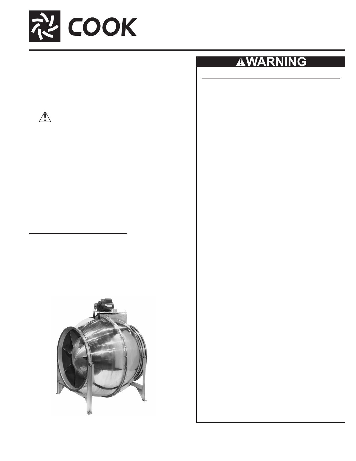
Loren Cook Centri-Vane CV Series User manual

1CV IO&M B51161-003
Receiving and Inspection
Carefully inspect the unit and accessories for any dam-
age and shortage immediately upon receipt of the unit.
•Turn the propeller by hand to ensure it turns freely and
does not bind.
•Record on the Delivery Receipt any visible sign of damage.
Handling
Lift the fan by the outside housing and support leg.
NOTICE! Never lift by the shaft, motor or housing.
Storage
If the fan is stored for any length of time prior to installa-
tion, store it in its original shipping crate and protect it from
dust, debris and weather.
CV
Centri-Vane®Aluminum Inline and Roof Fans
INSTALLATION, OPERATION AND MAINTENANCE MANUAL
CVB
Rotating Parts & Electrical Shock Hazard:
Fans should be installed and serviced by qualied person-
nel only.
Disconnect electric power before working on unit (prior to
removal of guards or entry into access doors).
Follow proper lockout/tagout procedures to ensure the unit
cannot be energized while being installed or serviced.
A disconnect switch should be placed near the fan in order
that the power can be swiftly cut off, in case of an emergen-
cy and in order that maintenance personnel are provided
complete control of the power source.
Grounding is required. All eld-installed wiring must be
completed by qualied personnel. All eld installed wiring
must comply with National Electric Code (NFPA 70) and all
applicable local codes.
Fans and blowers create pressure at the discharge and
vacuum at the inlet. This may cause objects to get pulled
into the unit and objects to be propelled rapidly from the
discharge. The discharge should always be directed in a
safe direction and inlets should not be left unguarded. Any
object pulled into the inlet will become a projectile capable
of causing serious injury or death.
When air is allowed to move through a non-powered fan,
the impeller can rotate, which is referred to as windmill-
ing. Windmilling will cause hazardous conditions due to
unexpected rotation of components. Impellers should be
blocked in position or air passages blocked to prevent draft
when working on fans.
Friction and power loss inside rotating components will
cause them to be a potential burn hazard. All components
should be approached with caution and/or allowed to cool
before contacting them for maintenance.
Under certain lighting conditions, rotating components may
appear stationary. Components should be veried to be
stationary in a safe manner, before they come into contact
with personnel, tools or clothing.
Failure to follow these instructions could result in death or
serious injury.
The attachment of roof mounted fans to the roof curb as
well as the attachment of roof curbs to the building struc-
ture must exceed the structural requirements based on the
environmental loading derived from the applicable building
code for the site. The local code ofcial may require varia-
tions from the recognized code based on local data. The
licensed engineer of record will be responsible for prescrib-
ing the correct attachment based on construction materi-
als, code requirements and environmental effects specic
to the installation.
®
This publication contains the installation, operation
and maintenance instructions for standard units of the
CV: Centri-Vane®Aluminum Inline and Roof Fans.
•CVD
•CVB
•CVR
•CVR-S
•CV/UCV-S
• CVS
Carefully read this publication and any
supplemental documents prior to any
installation or maintenance procedure.
Loren Cook catalog, CV, provides additional information
describing the equipment, fan performance, available
accessories and specication data.
For additional safety information, refer to AMCA Publica-
tion 410-96, Safety Practices for Users and Installers of
Industrial and Commercial Fans.
All of the publications listed above can be obtained from:
•lorencook.com
• 417-869-6474 ext. 166
For information and instructions on special equipment,
contact Loren Cook Company at 417-869-6474.

2CV IO&M B51161-003
Tolerance
Center
Distance
Maximum
Gap
Up thru
12” 1/16”
12” up
through
48
1/8”
Over 48” 1/4”
OFFSET ANGULAR OFFSET/ANGULAR
A
W
X
Y
ZB
CENTER
DISTANCE
(CD)
GAP GAP
Pulley Alignment
Pulley alignment is adjusted by loosening the motor pulley
setscrew and by moving the motor pulley on the motor shaft.
Figure 2 indicates where to measure
the allowable gap for the drive align-
ment tolerance. All contact points (in-
dicated by WXYZ) are to have a gap
less than the tolerance shown in the
above Tolerance table.
When the pulleys are not the same
width, the allowable gap must be
adjusted by half of the difference in
width. Figure 3 illustrates using a car-
penter’s square to adjust the position
of the motor pulley until the belt is parallel to the longer leg
of the square.
Final Installation Steps
1. Inspect fasteners and setscrews, particularly fan mounting
and bearing fasteners, and tighten according to the recom-
mended torque shown in the table below, Recommended
Torque for Setscrews/Bolts.
2. Inspect for correct voltage with voltmeter.
3. Ensure all accessories are installed.
4. Test the fan to be sure the rotation is the same as indicated
by the arrow marked Rotation.
Wheel Rotation
Test the fan to ensure the rotation of the wheel is the
same as indicated by the arrow marked Rotation.
115 and 230 Single Phase Motors
Fan wheel rotation is set correctly at the factory. Chang-
ing the rotation of this type of motor should only be at-
tempted by a qualied electrician.
208, 230, and 460, 3 Phase Motors
These motors are electri-
cally reversible by switching
two of the supply leads. For
this reason, the rotation of
the fan cannot be restricted
to one direction at the fac-
tory. See Wiring Diagrams
for specic information on
reversing wheel direction.
NOTICE! Do not allow the fan to run in the wrong di-
rection. This will overheat the motor and cause seri-
ous damage. For 3-phase motors, if the fan is running
in the wrong direction, check the control switch. It is
possible to interchange two leads at this location so
that the fan is operating in the correct direction.
To maintain good working condition of a CV when it is
stored outdoors, or on a construction site, follow the addi-
tional steps below:
• Cover the inlet and outlet, and belt tunnel opening to prevent
the accumulation of dirt and moisture in the housing
• Periodically rotate the wheel and operate dampers (if supplied)
to keep a coating of grease on all internal bearing parts
Installation
To prevent damage to the fan during shipping, motors 5 HP and
larger, and extremely heavy motors (cast iron or severe duty) are
shipped loose and must be eld mounted by bolting the motor on
the motor mounting plate in the existing mounting slots.
UCV Fan Installation
The fan support (roof curb) should provide a level surface for
installation. If the roof is pitched more than 1/2:12, a sloped curb
must be used to correct for the incline. If the unit is installed on
a non-level surface, the damper door pivot should be positioned
perpendicular to the peak of the roof.
Place fan over roof opening. Secure the fan with lag screws,
anchor bolts, or other suitable fasteners.
Wiring Installation
Direct Drive
Wire the electrical box on the blower housing.
Belt Drive
The motor can be wired directly since the motor is external to
the fan.
Leave enough slack in the wiring to allow for motor movement
when adjusting belt tension. Some fractional motors have to be
removed in order to make the connection with the terminal box at
the end of the motor. To remove motor, remove bolts securing mo-
tor base to power assembly. Do not remove motor mounting bolts.
NOTICE! Follow the wiring diagram in the disconnect
switch and the wiring diagram provided with the mo-
tor. Correctly label the circuit on the main power box
and identify the closed switch to promote safety (i.e.,
red tape over a closed switch).
Belt and Pulley Installation
Belt tension is determined by the sound of the belts when the
fan is rst started. The belts will produce a loud squeal, which dis-
sipates after the fan is operating at full capacity. If belt tension is
too tight or too loose, lost efciency and damage can occur.
Do not change the pulley
pitch diameter to change
tension. The change will re-
sult in a different fan speed.
1. Loosen the motor
plate adjustment nuts
on motor base and
move motor plate in
order that the belts
can easily slip into the
grooves on the pul-
leys. Never pry, roll,
or force the belts over
the rim of the pulley.
2. Adjust the motor plate
until proper tension is
reached. For proper
tension, a deection of approximately 1/4” per foot of center
distance should be obtained by rmly pressing the belt. See
Figure 3.
3. Lock the motor plate adjustment nuts in place.
4. Ensure pulleys are properly aligned. See Pulley Alignment.
1 foot
1/4 inch
Figure 2

3CV IO&M B51161-003
2 Speed, 2 Winding, 3 Phase
L1
T1
T2
T3Low Speed
Low Speed
Low Speed
High Speed
High Speed
High Speed
Motor
T13
T12
T11
L2Line
L3
To reverse:
High Speed - interchange leads T11 and T12.
Low Speed - interchange leads T1and T2.
Both Speeds - interchange any two line leads.
Typical Damper Motor Schematic
Fan
Motor
Damper
Motor*
Second
Damper
Motor
Transformer** Transformer**
L3
L2
L1
For 3 phase, damper motor voltage should be the same be-
tween L1and L2. For single phase application, disregard L3.
*Damper motors may be available in 115, 230 and 460 volt
models. The damper motor nameplate voltage should be veri-
ed prior to connection. **A transformer may be provided in
some installations to correct the damper motor voltage to the
specied voltage.
Operation
Pre-Start Checks
1. Lock out all the primary and secondary power sources.
2. Inspect fasteners and setscrews, particularly those used for
mounting the unit, and tighten if necessary.
3. Inspect belt tension and pulley alignment. (Remember, if
belt tension is correct, a loud squeal occurs as the fan in-
creases to full power.)
4. Inspect motor wiring.
5. Ensure the belt touches only the pulleys.
6. Rotate the prop to ensure it does not rub against the venturi.
7. Ensure fan and ductwork are clean and free of debris.
8. Test the fan to ensure the rotation of the propeller is the
same as indicated by the rotation label.
9. Close and secure all access doors.
10. Restore power to unit.
Start Up
Turn the fan on. In variable speed units, set the fan to its
lowest speed. Inspect for the following:
• Direction of rotation
• Excessive vibration
• Unusual noise
• Bearing noise
• Improper belt alignment or tension (listen for a continuous
squealing noise)
• Improper motor amperage or voltage
NOTICE! If a problem is discovered, immediately shut
o the fan. Lock out all electrical power and check
for the cause of the trouble. Refer to Troubleshooting.
Wiring Diagrams
Single Speed, Single Phase Motor
T-1
T-4
Ground B
L2
L1
Ground A
Line
When ground is required, attach to ground A or B with no. 6
thread forming screw. To reverse, interchange T-1 and T-4.
2 Speed, 2 Winding, Single Phase Motor
Ground A
Ground B
T-1
T-4
Low Speed
High Speed
L1
L2Line
When ground required, attach to ground A or B with No. 6
thread forming screw. To reverse, interchange T-1 and T-4
leads.
Single Speed, Single Phase, Dual Voltage
Ground B
J-10
T-5
Ground A
Link A
Link B
Low Voltage
Line
L2
L1
Ground A
Link A & B
L1
L2
Line
Ground B
T-5
J-10
When ground required, attach to ground A or B with No. 6
thread forming screw. To reverse, interchange T-5 and J-10
leads.
3-Phase, 9 Lead Motor
456
1
7
2
8
3
9
L1L2L3
456
789
12 3
L1L2L3
Low Voltage
208/230 Volts
High Voltage
460 Volts
3 Phase, 9 Lead Motor
Y-Connection
7
1
6789
456
12 3
Low Voltage
208/230 V
olts
High V
oltage
460 Volts
8
2
4
9
3
5
L
1
L
3
L
2
L1L3
L2
3 Phase, 9 Lead Motor
Delta-Connection
To reverse, interchange any two line leads.
2 Speed, 1 Winding, 3 Phase Motor
Motor
1
2
3
4
5
6
Together
High Speed
Line
L1
L2
L
3
1
2
3
4
5
6
Open
Low Speed
Line
L1
L2
L3
Motor
To reverse, interchange any two line leads. Motors require
magnetic control.

4CV IO&M B51161-003
Bearings should be relubricated in accordance with the
conditions chart below.
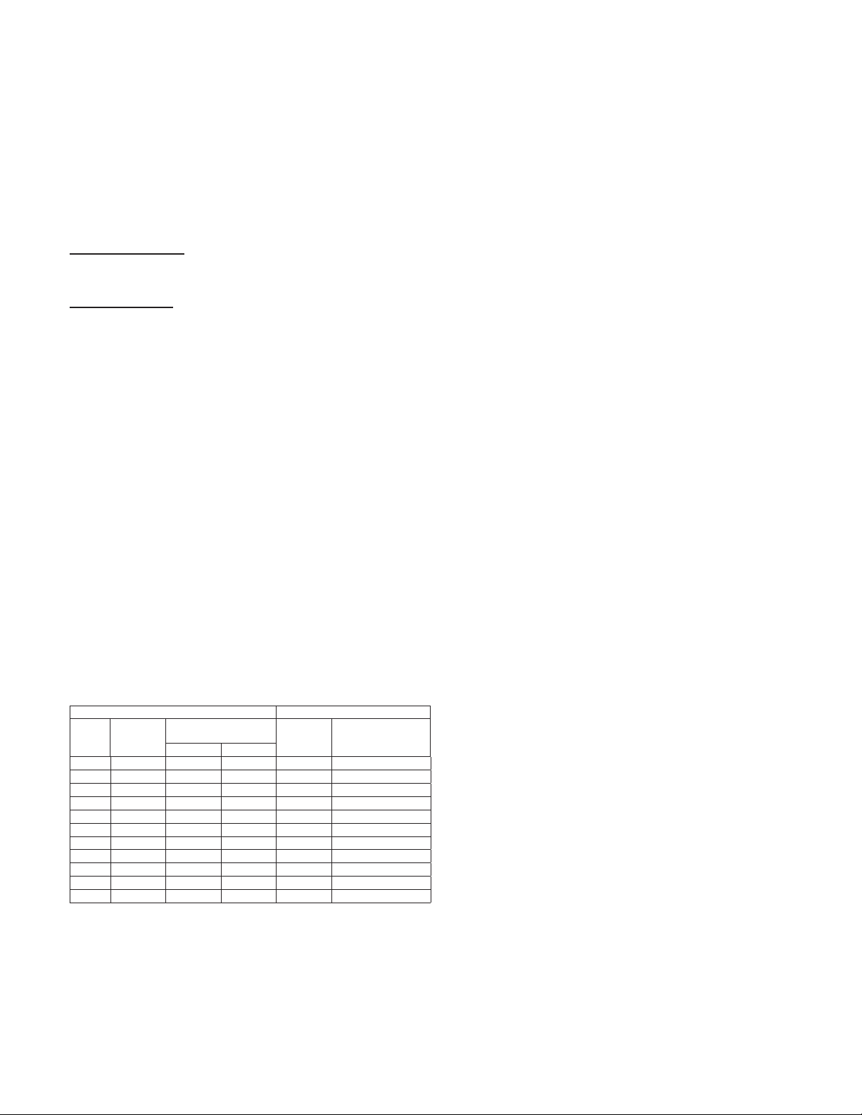
Conditions Chart
RPM Temp °F Greasing Interval
Up to 1000 -30 to 120 6 months
120 to 200 2 months
1000 to 3000 -30 to 120 3 months
120 to 200 1 month
Over 3000 -30 to 120 1 month
120 to 200 2 weeks
Any Speed < -30 Consult Factory
Any Speed > 200 1 week
For moist or otherwise contaminated installations; divide the in-
terval by a factor of three. For vertical shaft installations divide
the interval by a factor of two.
For best results, lubricate the bearing while the fan is in
operation. Pump grease in slowly until a slight bead forms
around the bearing seals. Excessive grease can damage
seal and reduce life through excess contamination and/or
loss of lubricant.
In the event that the bearing cannot be seen, use no more
than three injections with a hand operated grease gun.
Motor Bearings
Motors are provided with prelubricated bearings. Any
lubrication instructions shown on the motor nameplate su-
persede instructions below.
Direct Drive 1050/1075, 1200, 1300 & 1500 RPM units
use a prelubricated sleeve bearing that has a oil saturated
wicking material surrounding it. The initial factory lubrica-
tion is adequate for up to 10 years of operation under nor-
mal conditions. However, it is advisable to add lubricant
after three years. Use only LIGHT grade mineral oil or SAE
10W oil up to 30 drops.
If the unit has been stored for a year or more it is ad-
visable to lubricate as directed above. For units in severe
conditions, lubrication intervals should be reduced to half.
Motors without sleeve bearings (as described above) will
have grease lubricated ball or roller bearings. Motor bear-
ings without provisions for relubrication will operate up to
10 years under normal conditions with no maintenance. In
severe applications, high temperatures or excessive con-
taminates, it is advisable to have the maintenance depart-
ment disassemble and lubricate the bearings after 3 years
of operation to prevent interruption of service.
For motors with provisions for relubrication, follow inter-
vals of the table below.
Relubrication Intervals
Service
Conditions
Nema Frame Size
Up to and
Including 184T 213T-365T 404T and Larger
1800
RPM
and
Less
Over
1800
RPM
1800
RPM
and
Less
Over
1800
RPM
1800 RPM
and Less
Over
1800
RPM
Standard 3 yrs. 6 months 2 yrs. 6 months 1 yr. 3 months
Severe 1 yr. 3 months 1 yr. 3 months 6 months 1 month
Motors are provided with a polyurea mineral oil NGLI #2
grease. All additions to the motor bearings are to be with
a compatible grease such as Exxon Mobil Polyrex EM and
Chevron SRI.
The above intervals should be reduced to half for vertical
shaft installations.
Inspection
Inspection of the fan should be conducted at the rst 30
minute, 8 hour and 24 hour intervals of satisfactory op-
eration. During the inspections, stop the fan and inspect as
per the following directions.
30 Minute Interval
Inspect bolts, setscrews, and motor mounting bolts. Ad-
just and tighten as necessary.
8 Hour Interval
Inspect belt alignment and tension. Adjust and tighten as
necessary.
24 Hour Interval
Inspect belt tension. Adjust and tighten as necessary.
Maintenance
Establish a schedule for inspecting all parts of the fan.
The frequency of inspection depends on the operating
conditions and location of the fan.
Inspect fans exhausting corrosive or contaminated air
within the rst month of operation. Fans exhausting con-
taminated air (airborne abrasives) should be inspected ev-
ery three months. Clean the propeller and air inlets if ma-
terial build-up is excessive. Excessive build-up can cause
imbalance and failure of the propeller. Regular inspections
are recommended for fans exhausting non-contaminated
air. It is recommended the following inspections be
conducted twice per year.
• Inspect bolts and setscrews for tightness. Tighten as
necessary
• Inspect belt wear and alignment. Replace worn belts with new
belts and adjust alignment as needed. See Belt and Pulley
Installation, page 2
• Bearings should be inspected as recommended in the
Conditions Chart
• Inspect for cleanliness. Clean exterior surfaces only.
Removing dust and grease on motor housing assures proper
motor cooling
Lubricants
Loren Cook Company uses petroleum lubricant in a lith-
ium base conforming to NLGI grade 2 consistency. Other
grades of grease should not be used unless the bearings
and lines have been ushed clean. If another grade of
grease is used, it should be lithium-based.
An NLGI grade 2 grease is a light viscosity, low-torque,
rust-inhibiting lubricant that is water resistant. Its tempera-
ture range is from -30°F to +200°F and capable of intermit-
tent highs of +250°F.
Fan Bearings
The fan bearings are provided prelubricated. Any spe-
cialized lubrication instructions on fan labels supersedes
information provided herein. Bearing grease is a petroleum
lubricant in a lithium base conforming to an NLGI #2 con-
sistency. If user desires to utilize another type of lubricant,
they take responsibility for ushing bearings and lines, and
maintaining a lubricant that is compatible with the installa-
tion.
An NLGI #2 grease is a light viscosity, low-torque, rust-
inhibiting lubricant that is water resistant. Its temperature
range is from -30°F to 200°F and capable of intermittent
highs of 250°F.

5CV IO&M B51161-003
Bearing Replacement
The fan bearings are ange ball bearings.
1. Loosen the motor plate adjustment bolts, then slide
the motor plate so the belt will easily slip off.
2. Remove the driven pulley by loosening the setscrew.
3. Separate the outer housing halves.
4. Remove wheel, then loosen the setscrews on the hub
that holds the shaft and remove the hub plate. (Refer
to hub removal instructions below.)
5. Remove the bolts next to the straightening vanes and
pull the inner housing out.
6. Loosen the bearing setscrews and hold-down bolts,
then slide shaft out.
7. Sand the burrs on the shaft where the setscrews were
located.
8. Slide new bearings onto the shaft to the desired lo-
cation and loosely mount bearings onto the bearing
support. Bearing bolts and setscrews should be loose
enough to allow shaft positioning.
9. Replace the hub plate and wheel, align properly and
then tighten bearing hold-down bolts securely to the
bearing supports.
10. Align setscrews bearing to bearing and secure tightly
to the shaft.
Never tighten both pairs of setscrews before securing
bearing mounting bolts. This may damage the shaft.
11. Reassemble the unit.
12. Inspect the wheel position again. If necessary, read-
just by loosening the bearing bolts and setscrews and
repeat from step 5.
Hub Removal
1. Drill two 1/4” diameter holes, 180°apart centered ap-
proximately between the shaft and the outside diam-
eter of the hub, 3/8” to 1/2” in depth.
2. Tap 1/4” holes to 5/16” thread with a 5/16” hole tap. Do
not drill or tap greater than recommended.
3. Screw the puller arms to the full depth of the threads
into the tapped holes. Align center of the puller with
the center of the shaft. Ensure all setscrews in the
hub, normally two, are fully removed.
4. Slowly remove wheel from the shaft.
Recommended Puller
Lisle No. 45000 Steering Wheel Puller. This puller is
available at most automotive parts retail outlets.
Motor Services
Should the motor prove defective within a one-year pe-
riod, contact your local Loren Cook representative or your
nearest authorized electric motor service representative.
Changing Shaft Speed
All belt driven Propeller Wall fans with motors up to and
including 5 HP are equipped with variable pitch pulleys. To
change the fan speed, perform the following:
1. Loosen setscrew on driver (motor) pulley and remove
key, if equipped.
2. Open or close the groove facing to change the pitch
diameter.
Speed Reduction
Open the pulley in order that the belt rests deeper in the
groove.
Speed Increase
Close the pulley in order that the belt rests higher in the
groove. Ensure RPM limits of the fan and the horsepow-
er limits of the motor are maintained.
3. Retighten pulley setscrew on one of the at areas of
the motor shaft.
4. After the adjustment is made, check for proper belt
tension. See the Belt and Pulley Installation section.
Pulley and Belt Replacement
1. Remove pulleys from their respective shafts.
2. Clean the motor and fan shafts.
3. Clean bores of pulleys and coat the bores with heavy oil.
4. Remove grease, rust, or burrs from the pulleys.
5. Clean the bores of the pulleys and place a light coat of
oil on the bores.
6. Remove burrs from shaft by sanding.
7. Place fan pulley on fan shaft and motor pulley on its shaft.
Do not hammer the pulleys onto the shafts because
this may damage the bearings.
8. Tighten in place.
9. Install belts on pulleys and align as described in the
Belt and Pulley Installation section.
Recommended Torque for Setscrews/Bolts (IN-LB)
Setscrews Hold Down Bolts
Size
Key Hex
Across
Flats
Recommended
Torque Size Recommended
Torque
Min. Max.
#8 5/64” 15 21 3/8”-16 324
#10 3/32” 27 33 1/2”-13 780
1/4 1/8“ 70 80 5/8”-11 1440
5/16 5/32” 140 160 3/4”-10 2400
3/8 3/16” 250 290 7/8”-9 1920
7/16 7/32” 355 405 1”-8 2700
1/2 1/4“ 560 640 1-1/8”-7 4200
5/8 5/16” 1120 1280 1-1/4”-7 6000
3/4 3/8” 1680 1920 - -
7/8 1/2” 4200 4800 - -
1 9/16” 5600 6400 - -

6CV IO&M B51161-003
Parts List
CVD
Air Flow
1
2
3
4
5
6
7
Part No. Part Description (Sizes 70-180)
1 Outer Discharge Housing
2 Motor Plate
3Wheel Assembly
4 Outer Inlet Housing
5 Support Leg
6 Rubber Channel Isolator
7 Motor
CVB
1
2
3
4
5
7
8
910
11
12
Air Flow
6
Part No. Part Description (Sizes 12-36)
1 Belt Set
2 Motor
3 Motor Plate
4 Motor Plate Saddle
5Wheel Assembly
6 Bearings
7 Bearing Plate
8 Outer Inlet Housing
9 Support Legs
10 Rubber Channel Isolator
11 Shaft
12 Outer Discharge Housing
Troubleshooting
Problem and Potential Cause
Low Capacity or Pressure:
• Incorrect direction of rotation. Make sure the fan rotates
in same direction as the arrows on the motor or belt drive
assembly
• Poor fan inlet conditions. There should be a straight clear
duct at the inlet
• Improper wheel alignment
Excessive Vibration and Noise:
• Damaged or unbalanced wheel
• Belts too loose; worn or oily belts
• Speed too high
• Incorrect direction of rotation. Make sure the fan rotates
in same direction as the arrows on the motor or belt drive
assembly
• Bearings need lubrication or replacement
• Fan surge
Overheated Motor:
• Motor improperly wired
• Incorrect direction of rotation. Make sure the fan rotates
in same direction as the arrows on the motor or belt drive
assembly
• Cooling air diverted or blocked
• Improper inlet clearance
• Incorrect fan RPMs
• Incorrect voltage
Overheated Motor:
• Improper bearing lubrication
• Excessive belt tension

7CV IO&M B51161-003
CVS
1
2
1
4
6
2
5
7
8
9
3
11
10
Air Flow
Part No. Part Description (Sizes 12-36)
1 Belt Set
2 Motor Plate
3 Motor
4 Outer Discharge Housing
5 Belt
6 Outer Inlet Housing
7Wheel Assembly
8 Hub
9 Bearings
10 Shaft
11 Mounting Feet
CVR
1
2
3
45
6
7
89
10
11
Air Flow
12
Part No. Part Description (Sizes 10-36)
1Topcap Assembly
2 Post
3 Outer Discharge Housing
4 Belt Set
5 Belt Guard
6 Motor
7 Motor Plate
8 Motor Plate Saddle
9Wheel Assembly
10 Bearing Plate
11 Outer Inlet Housing
12 Bearings
CVR-S
1
2
3
4
5
6
7
8
9
10
11
12
Air Flow
Part No. Part Description (Sizes 10-36)
1Topcap Assembly
2 Post
3Wheel Assembly
4 Motor Plate Saddle
5 Motor Plate
6 Motor
7 Belt Guard
8 Belt Set
9 Outer Discharge Housing
10 Bearings
11 Outer Inlet Housing
12 Bearing Plate
UCV
1
23
4
5
6
7
8
9
10
11
12
13
Air Flow
Part No. Part Description (Sizes 10-36)
1Damper Assembly
2 Outer Discharge Housing
3 Belt Set
4 Belt Guard
5 Motor
6 Motor Plate
7 Motor Plate Saddle
8 Bearing Plate
9Wheel Assembly
10 Base
11 Outer Inlet Housing
12 Bearings
13 Shaft

8CV IO&M B51161-003
UCV-S
1
23
4
5
6
7
8
9
10
11
12
13
Air Flow
Part No. Part Description (Sizes 10-36)
1Damper Assembly
2 Motor Plate Mount
3 Motor
4 Weather Cover
5 Belt Set
6 Main Housing
7 Bearing Plate
8Wheel Assembly
9 Base
10 Outer Inlet Housing
11 Bearings
12 Shaft
13 Outer Discharge Housing
Limited Warranty
Loren Cook Company warrants that your Loren Cook fan was manufactured free of defects in materials and workmanship, to the extent stated herein.
For a period of ve (5) year after date of shipment, we will replace any parts found to be defective without charge, except for shipping costs which will be
paid by you. This warranty is granted only to the original purchaser placing the fan in service. This warranty is void if the fan or any part thereof has been
altered or modied from its original design or has been abused, misused, damaged or is in worn condition or if the fan has been used other than for the
uses described in the company manual. This warranty does not cover defects resulting from normal wear and tear. To make a warranty claim, notify Loren
Cook Company, General Ofces, 2015 East Dale Street, Springeld, Missouri 65803-4637, explaining in writing, in detail, your complaint and referring to
the specic model and serial numbers of your fan. Upon receipt by Loren Cook Company of your written complaint, you will be notied, within thirty (30)
days of our receipt of your complaint, in writing, as to the manner in which your claim will be handled. If you are entitled to warranty relief, a warranty ad-
justment will be completed within sixty (60) business days of the receipt of your written complaint by Loren Cook Company. This warranty gives only the
original purchaser placing the fan in service specically the right. You may have other legal rights which vary from state to state.
Corporate Ofces: 2015 E. Dale St. Springeld, MO 65803
Phone 417-869-6474 | Fax 417-862-3820 | lorencook.com
July 2017
This manual suits for next models
7
Table of contents
Other Loren Cook Fan manuals