neno LEADX Ultra User manual
NENO LEADX Ultra Manual
© NENO-CNC Schweiz 2023 Seite | 1
NENO LEADX Serie
NENO LEADX Ultra
Assembly instructions, operating
instructions and safety V1.2

NENO LEADX Ultra Manual
© NENO-CNC Schweiz 2023 Seite | 2
Index
General.................................................................................................................................................... 6
About the NENO LEADX Ultra.............................................................................................................. 6
Limitation ............................................................................................................................................ 7
Safety....................................................................................................................................................... 8
Responsibility of the operator............................................................................................................. 8
Personal protective device.................................................................................................................. 8
Safety....................................................................................................................................................... 9
Ambient conditions ............................................................................................................................. 9
Residual risk......................................................................................................................................... 9
Required tools ....................................................................................................................................... 10
Notes on assembly ................................................................................................................................ 10
1.0 Explanation of the basics................................................................................................................. 11
1.0.1 Machine axes............................................................................................................................ 11
1.0.2 Guidance................................................................................................................................... 12
1.1 Cleaning before assembly ............................................................................................................... 13
1.1.1 Cleaning procedure .................................................................................................................. 13
2.0 Y-axis................................................................................................................................................ 14
2.1 C-beam and HGR rail ................................................................................................................... 14
2.1.1 HGR rail preparation................................................................................................................. 15
2.1.2 Attaching the HGR rail to the C-beam...................................................................................... 16
2.1.3 Alignment tool.......................................................................................................................... 17
2.1.4 HGH storage blocks .................................................................................................................. 18
2.1.5 Insertion of T-nuts.................................................................................................................... 19
2.2 Y-plate.............................................................................................................................................. 20
2.2.1 Y-plate and bearing block......................................................................................................... 20
2.3 Ball screw......................................................................................................................................... 21
2.3.1 Ball nut and ball nut plate ........................................................................................................ 21
2.3.2 Ball nut plate and Y-plate......................................................................................................... 22
2.4 End plates........................................................................................................................................ 23
2.4.1 End plate (fixed end) ................................................................................................................ 23
2.4.2 End plate (loose end)................................................................................................................ 24
2.5 FK and FF camps .............................................................................................................................. 25
2.5.1 FF bearings (loose bearings)..................................................................................................... 25
2.5.2 FK warehouse (fixed bearings)................................................................................................. 26
2.5.3 Locking nut and diaphragm coupling ....................................................................................... 27

NENO LEADX Ultra Manual
© NENO-CNC Schweiz 2023 Seite | 3
2.6 Aligning............................................................................................................................................ 28
2.6.1 Tightening the ball nut adapter plate....................................................................................... 28
2.6.2 Fixed bearings........................................................................................................................... 29
2.6.3 Stepper motor .......................................................................................................................... 30
2.6.4 Loose bearing ........................................................................................................................... 31
2.6.5 Retaining ring ........................................................................................................................... 32
2.7 Axis complete .................................................................................................................................. 33
2.7.1 Completed Y-axis...................................................................................................................... 33
2.7.2 Completed Y1 and Y2 axes ....................................................................................................... 34
2.8 Lubrication of the Y1 and Y2 axes ................................................................................................... 35
2.8.1 HGH bearing blocks .................................................................................................................. 35
2.8.2 Ball screw.................................................................................................................................. 35
3.0 Substructure.................................................................................................................................... 36
3.1 T-nuts............................................................................................................................................... 36
3.1.1 Insertion of T-nuts - front and rear profile............................................................................... 36
3.1.2 Mounting brackets - front and rear profile.............................................................................. 37
3.1.3 Insertion of T-nuts - middle sections........................................................................................ 38
3.1.4 Mounting brackets - middle sections....................................................................................... 39
3.1.5 Preparation of the substructure completed. ........................................................................... 40
3.2 Substructure fixed side.................................................................................................................... 41
3.2.1 - Attach the Y2 axle to the reference side................................................................................ 41
3.2.2 - Attachment of the front (loose end)...................................................................................... 42
3.2.3 - Attachment of the middle sections to the Y2 axis. ................................................................ 43
3.2.4 - Attachment of the back (fixed end) ....................................................................................... 44
3.2.5 - Attachment of the rear profile to the Y-end plate (fixed end)............................................... 45
3.2.6 - Attachment of the front to the Y-end plate (loose end)........................................................ 46
3.3 Substructure –loose side ................................................................................................................ 47
3.3.1 - Place the second Y-axis on the sliding side. ........................................................................... 47
3.3.2 - Attachment of the front (loose end)...................................................................................... 48
3.3.3 - Attachment of the middle sections to the Y-axis................................................................... 49
3.3.4 - Attachment of the back (fixed end) ....................................................................................... 50
3.3.5 - Attachment of the rear profile to the Y-end plate (fixed end)............................................... 51
3.3.6 - Attachment of the front to the Y-end plate (loose end)........................................................ 52
3.4 - Drag chain support........................................................................................................................ 53
3.4.1 - Attachment of the profile ...................................................................................................... 53
3.4.2 - Attachment to the substructure ............................................................................................ 54

NENO LEADX Ultra Manual
© NENO-CNC Schweiz 2023 Seite | 4
3.4.3 - End caps ................................................................................................................................. 55
3.5 Substructure complete.................................................................................................................... 56
4.0 X-axis................................................................................................................................................ 57
4.1 C-beam and HGR rail ....................................................................................................................... 57
4.1.1 HGR rail preparation................................................................................................................. 57
4.1.2 Attaching the HGR rails to the C-Beam profile......................................................................... 58
4.1.3 Alignment Tool ......................................................................................................................... 59
4.1.4 HGH storage blocks .................................................................................................................. 60
4.1.5 X-plate and HGH slide............................................................................................................... 61
4.1.6 Insertion of slot stones in the C-beam profile.......................................................................... 62
4.1.7 Inserting T-nuts into the 4040 Profile ...................................................................................... 63
4.2 Extruded profiles and Y-plates ........................................................................................................ 64
4.2.1 C-beam and 4040 on the Y-plates............................................................................................ 64
4.2.2 Angle brackets at the Y-plate ................................................................................................... 65
4.2.3 C-beam and 4040 angles .......................................................................................................... 67
4.3 Ball screw......................................................................................................................................... 69
4.3.1 Ball nut and ball nut plate ........................................................................................................ 69
4.3.2 Insertion of the ballscrew into the X-axis................................................................................. 70
4.3.3 Ball nut plate and X-plate......................................................................................................... 71
4.4 FK and FF camps .............................................................................................................................. 72
4.4.1 FF bearings (loose bearings)..................................................................................................... 72
4.4.2 FK storage (fixed bearings)....................................................................................................... 73
4.4.3 Locking nut and diaphragm coupling ....................................................................................... 74
4.5 Aligning............................................................................................................................................ 75
4.5.1 Tightening the ball nut adapterplate ....................................................................................... 75
4.5.2 Fixed bearings........................................................................................................................... 76
4.5.3 Stepper motor .......................................................................................................................... 77
4.5.4 Loose bearing ........................................................................................................................... 78
4.5.5 Retaining ring ........................................................................................................................... 79
4.6 X-axis complete ............................................................................................................................... 80
4.7 Lubrication of the X-axis.................................................................................................................. 81
4.7.1 HGH bearing blocks .................................................................................................................. 81
4.7.2 Ball screw.................................................................................................................................. 81
5.0 Z-axis................................................................................................................................................ 82
5.1 C-beam and MGN rails .................................................................................................................... 82
5.1.1 MGN rail preparation ............................................................................................................... 82

NENO LEADX Ultra Manual
© NENO-CNC Schweiz 2023 Seite | 5
5.1.2 Attaching the MGN rail to the C-Beam .................................................................................... 83
5.1.3 Alignment Tool ......................................................................................................................... 84
5.1.4 MGN 15 Bulkheads................................................................................................................... 85
5.2 Z-plate.............................................................................................................................................. 86
5.3 Ball screw......................................................................................................................................... 87
5.3.1 Ball nut and spherical nut plate................................................................................................ 87
5.3.2 Ball nut plate and Z-plate ......................................................................................................... 88
5.4 End plates........................................................................................................................................ 89
5.4.1 End plate (fixed end) ................................................................................................................ 89
5.4.2 End plate (loose end)................................................................................................................ 90
5.5 FK and FF bearings........................................................................................................................... 91
5.5.1 FF bearing (loose)..................................................................................................................... 91
5.5.2 FK bearing (fixed)...................................................................................................................... 92
5.6 Aligning............................................................................................................................................ 93
5.6.1 Tightening the ball nut adapter-plate ...................................................................................... 93
5.6.2 Fixed bearing ............................................................................................................................ 94
5.6.3 Stepper motor .......................................................................................................................... 95
5.6.4 Loose bearing ........................................................................................................................... 97
5.6.5 Retaining ring ........................................................................................................................... 98
5.7 Z-axis complete................................................................................................................................ 99
5.8 Lubrication of the Z-axis................................................................................................................ 100
5.8.1 MGN warehouse..................................................................................................................... 100
5.8.2 Ball screw................................................................................................................................ 100
5.9 Joining X and Z axes together........................................................................................................ 101
6.0 Final work ...................................................................................................................................... 102
6.1 Description .................................................................................................................................... 102
6.2 Squaring the machine.................................................................................................................... 103
6.2.1 - Front..................................................................................................................................... 103
6.2.2 - Back ...................................................................................................................................... 104
6.2.3 Middle sections ...................................................................................................................... 105
6.3 Carrying out the measurements.................................................................................................... 106
7 Care and maintenance ..................................................................................................................... 107
7.1 Preventive maintenance ........................................................................................................... 107
8.0 spoilboard...................................................................................................................................... 108

NENO LEADX Ultra Manual
© NENO-CNC Schweiz 2023 Seite | 6
General
About the NENO LEADX Ultra
Congratulations on purchasing your NENO LEADX Ultra basic kit!
The NENO LEADX Ultra is a CNC milling machine of the latest generation.
After the success of our simple but stable LEADX Pro, we were increasingly confronted with inquiries
about more complex and stable milling machines.
The LEADX Ultra is based on the same aluminium profiles as the LEADX Pro, but dispenses with the
roller system and the trapezoidal threaded spindles and uses high-precision linear guides and ball
screws.
In order to stand out from the competition on the market, the LEADX Ultra uses massive HGR15
linear guides that can absorb 3x as many forces as the usual MGN15 linear guides.
The LEADX Ultra uses high-precision rolled ball screws with a diameter of 12mm in precision class C7
on all axes.
For this purpose, all aluminium profiles used are made in Europe.
We wish You a lot of fun with the assembly!
We are here for You. Write to us if you don't know what to do: Support@nenocnc.ch

NENO LEADX Ultra Manual
© NENO-CNC Schweiz 2023 Seite | 7
Limitation
The information and notes in this manual have been compiled taking into account the applicable
standards, regulations as well as the applicable case law and the current state of the art.
No liability is assumed for improper assembly, wiring, commissioning, use or maintenance.
The manufacturer NENO-CNC is also not liable in the following cases:
1. Failure to follow the instructions
2. Incorrect assembly
3. Inappropriate use
4. Arbitrary intervention and modification of the components
5. Technical conversions of any kind
6. Use of third-party accessories or non-approved spare parts
The actual scope of delivery may deviate from the explanations and illustrations described here in
the event of special designs, the use of additional ordering options, introductory promotions, or due
to the latest technical changes. The obligations agreed in the delivery contract, the general terms and
conditions as well as the terms of delivery of the manufacturer NENO-CNC and the legal regulations
valid at the time of conclusion of the contract apply. Furthermore, the statutory warranty provisions
apply.
Read these assembly instructions and the operating and safety instructions
carefully and make sure several times in each step of the instructions that you
have not made any mistakes during assembly.

NENO LEADX Ultra Manual
© NENO-CNC Schweiz 2023 Seite | 8
Safety
Responsibility of the operator
The operator of the NENO LEADX Ultra is responsible for the following points:
1. The safety instructions have been read and understood.
2. The construction was carried out completely according to instructions.
3. The CNC milling machine has been properly tested before each operation and is only put into
operation in perfect condition.
4. The CNC milling machine is only used with accessories approved by the manufacturer.
5. Possible precautions (hearing protection, safety goggles, distance to the spindle, etc.) have
been properly taken before commissioning.
6. Minors have reached the age of 14 before use and a basic technical understanding is
available.
7. The CNC milling machine must be operated and stored out of the reach of children.
8. Safety devices such as the emergency stop switch must always be freely accessible.
9. If you want to make adjustments to the machine, the associated controller or various
system-guided tools, unplug the power as a precaution.
10. The owner of the machine must ensure that all persons working with the CNC milling
machine have read and understood the safety instructions.
11. The owner, as well as anyone present while actively working with the machine, must wear
protective clothing as described in this manual.
Personal protective device
Please always ensure that basic personal protection measures are observed at every company and
for bystanders.
12. Safety goggles (protection of the eyes from flying chips and broken milling cutter)
13. Hearing protection (protection of the ears from loud background noise)
14. Protective gloves (protection of hands from heat and cuts when handling milling cutters)
15. Tight-fitting work clothes (protection against accidental entanglement of clothing in spindles
or guides)
16. Secure shoulder-length or even longer scalp hair with a hairnet or cap so that it cannot get
into the linear guides and/or the rotating milling tools.
17. Protective mask (protection against carcinogenic fumes and milling dusts)

NENO LEADX Ultra Manual
© NENO-CNC Schweiz 2023 Seite | 9
Safety
Ambient conditions
Carry out the construction and operation of the milling machine only on a solid, flat surface. It should
stand securely and not be able to slip.
Make sure there is enough space around the machine so that you can work comfortably and the
machine can fully extend its travels. Also keep a safe distance from other machines.
Never touch system-guided tools or moving components during operation. Moving parts (e.g. Y-
bridge gantry) can suddenly and unexpectedly change direction. Depending on the operating
regulations, a barrier or covering of moving parts may be necessary.
Keep your workspace clean and well lit. Keep children and others away or at a minimum distance
while using the milling machine. There is a massively increased risk of injury.
Residual risk
Even if all precautions are observed, there is always a certain degree of residual risk for persons or
property.
It must always be ensured that the machine is operated with caution and caution.
For your own safety, please always ensure that you are not unfocused or under the influence of
various means that could affect your mental activity.
NENO LEADX Ultra Manual
© NENO-CNC Schweiz 2023 Seite | 10
Required tools
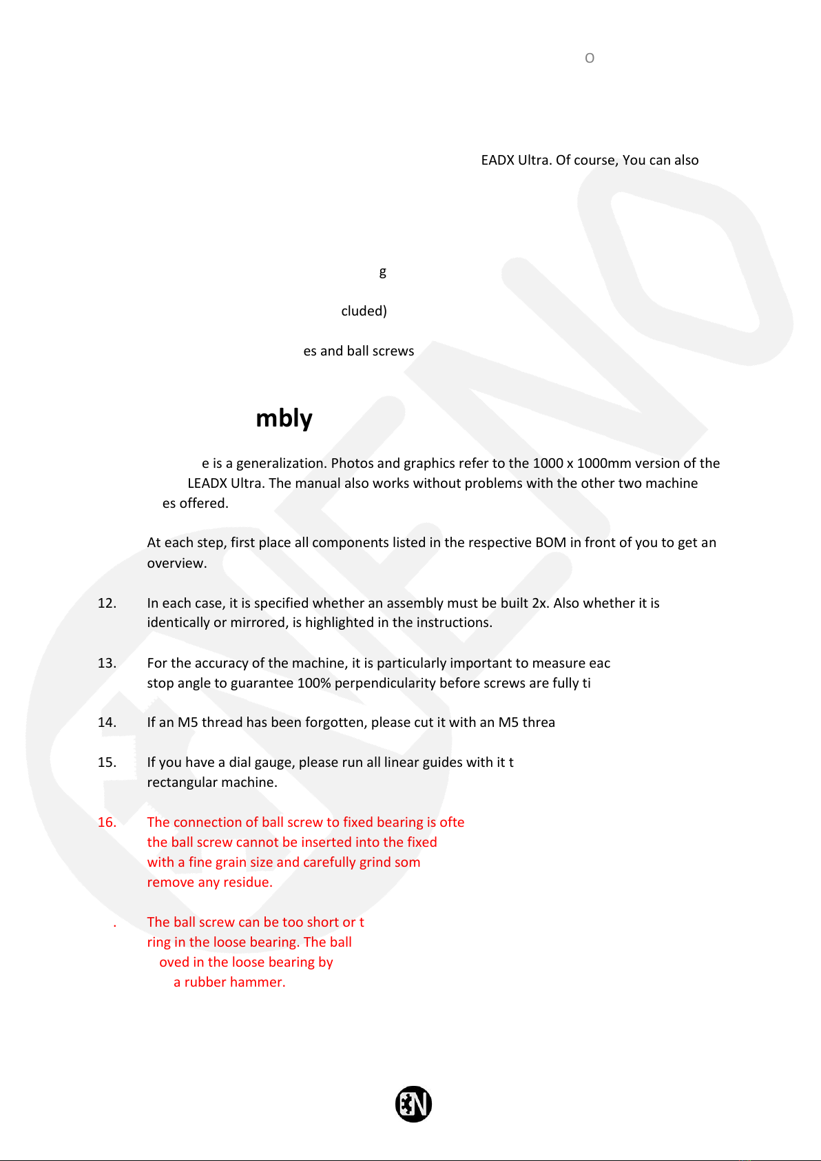
We recommend a set of tools needed to assemble the NENO LEADX Ultra. Of course, You can also
use complementary tools.
1. Allen key set
2. Wrench or Ratchet Set
3. Various screwdrivers
4. Possibly M5 thread cutter for recutting
5. Square ruler
6. Linear guides alignment tool (included)
7. Retaining ring pliers
8. Grease gun for linear drives and ball screws
9. Grease to grease gun
Notes on assembly
10. This guide is a generalization. Photos and graphics refer to the 1000 x 1000mm version of the
NENO LEADX Ultra. The manual also works without problems with the other two machine
sizes offered.
11. At each step, first place all components listed in the respective BOM in front of you to get an
overview.
12. In each case, it is specified whether an assembly must be built 2x. Also whether it is built
identically or mirrored, is highlighted in the instructions.
13. For the accuracy of the machine, it is particularly important to measure each angle with a
stop angle to guarantee 100% perpendicularity before screws are fully tightened.
14. If an M5 thread has been forgotten, please cut it with an M5 thread cutter.
15. If you have a dial gauge, please run all linear guides with it to guarantee a completely flat and
rectangular machine.
16. The connection of ball screw to fixed bearing is often ground to very minimal tolerances. If
the ball screw cannot be inserted into the fixed bearing with light pressure, take a sandpaper
with a fine grain size and carefully grind some material from the contact surface. Then
remove any residue.
17. The ball screw can be too short or too long after fixing in the fixed bearing to attach the snap
ring in the loose bearing. The ball bearing, which is located in the loose bearing, can be easily
moved in the loose bearing by 1-2mm in both directions using a nut from a socket wrench set
and a rubber hammer.

NENO LEADX Ultra Manual
© NENO-CNC Schweiz 2023 Seite | 11
1.0 Explanation of the basics
1.0.1 Machine axes
Before we start, we start with the basic structure of a milling machine for reasons of understanding.
On the picture we can see the different axes that a classic portal milling machine has. The X-Portal
runs on the two Y-axes. The Z-axis runs on the X-Portal. Please memorize these basics, as this basic
understanding can be very helpful during assembly.
Z-axis (Z)
NENO LEADX Ultra Manual
© NENO-CNC Schweiz 2023 Seite | 12
1.0.2 Guidance
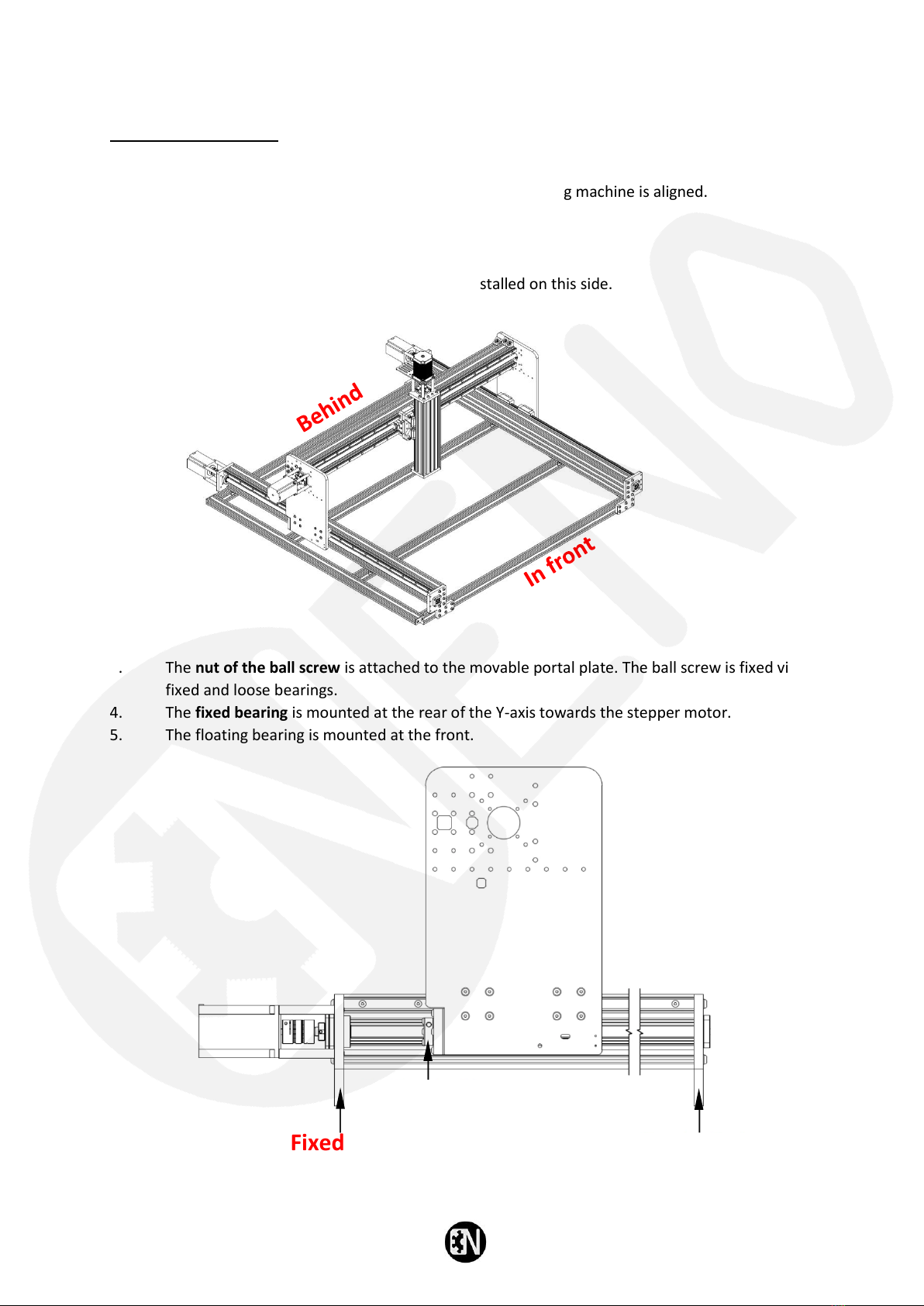
For better orientation, it is important to know how the CNC milling machine is aligned.
1. Front: The Z-axis is mounted on this side.
2. Rear: The stepper motors of the Y-axes are installed on this side.
3. The nut of the ball screw is attached to the movable portal plate. The ball screw is fixed via
fixed and loose bearings.
4. The fixed bearing is mounted at the rear of the Y-axis towards the stepper motor.
5. The floating bearing is mounted at the front.
Fixed end
Floating
(loose) end
Nut of the ball screw
NENO LEADX Ultra Manual
© NENO-CNC Schweiz 2023 Seite | 13
1.1 Cleaning before assembly
It is recommended to degrease guide rails and block carriages before assembly. The grease, which is
located on the guide rails and block carriages when preserved, is called bearing grease. This grease is
intended to prevent rusting of the guides during storage and shipping. This fat can be removed by
alcohol-based cleaners, e.g. isopropanol.
Attention: Never remove the plastic brackets from the block carriages to avoid losing the ball
bearings. During installation, the block carriages are pushed directly from the plastic brackets onto
the guide rails.
1.1.1 Cleaning procedure
1. Fill a small bowl with the cleaning solution.
2. Place the block carriages in so that they are completely covered and let it linger for 10
minutes.
3. Move the block carriages back and forth on the plastic brackets.
4. Remove the block trolleys from the cleaning solution and let them dry for at least an hour.
5. Screw the grease nipples onto the block carriages.
6. Take household paper, wet it with the cleaning solution and degrease the guide rails as well.
Perform this cleaning procedure right before assembly. Do not leave any of the cleaned parts for
more than a few hours, otherwise rust may occur. After each work step, the greasing of the
respective axis is discussed.
If you do not want to assemble the entire machine in one day, grease the mentioned parts before
assembly to prevent corrosion.
NENO LEADX Ultra Manual
© NENO-CNC Schweiz 2023 Seite | 14
2.0 Y-axis
It is recommended to read and understand all steps between 2.1 and 2.7 before starting assembly.
The t-slot nuts must be inserted into the channel of the aluminium profile for later steps, and if they
are missing, the steps must be dismantled again.
2.1 C-beam and HGR rail
Find the C-Beam profile and the HGR rails used for your Y-axis. If your machine size differs from X to
Y, e.g. if you purchased a size of 1000 mm x 1500 mm, the second length, which in this example is
1500 mm, is the Y-axis.
NENO LEADX Ultra Manual
© NENO-CNC Schweiz 2023 Seite | 15
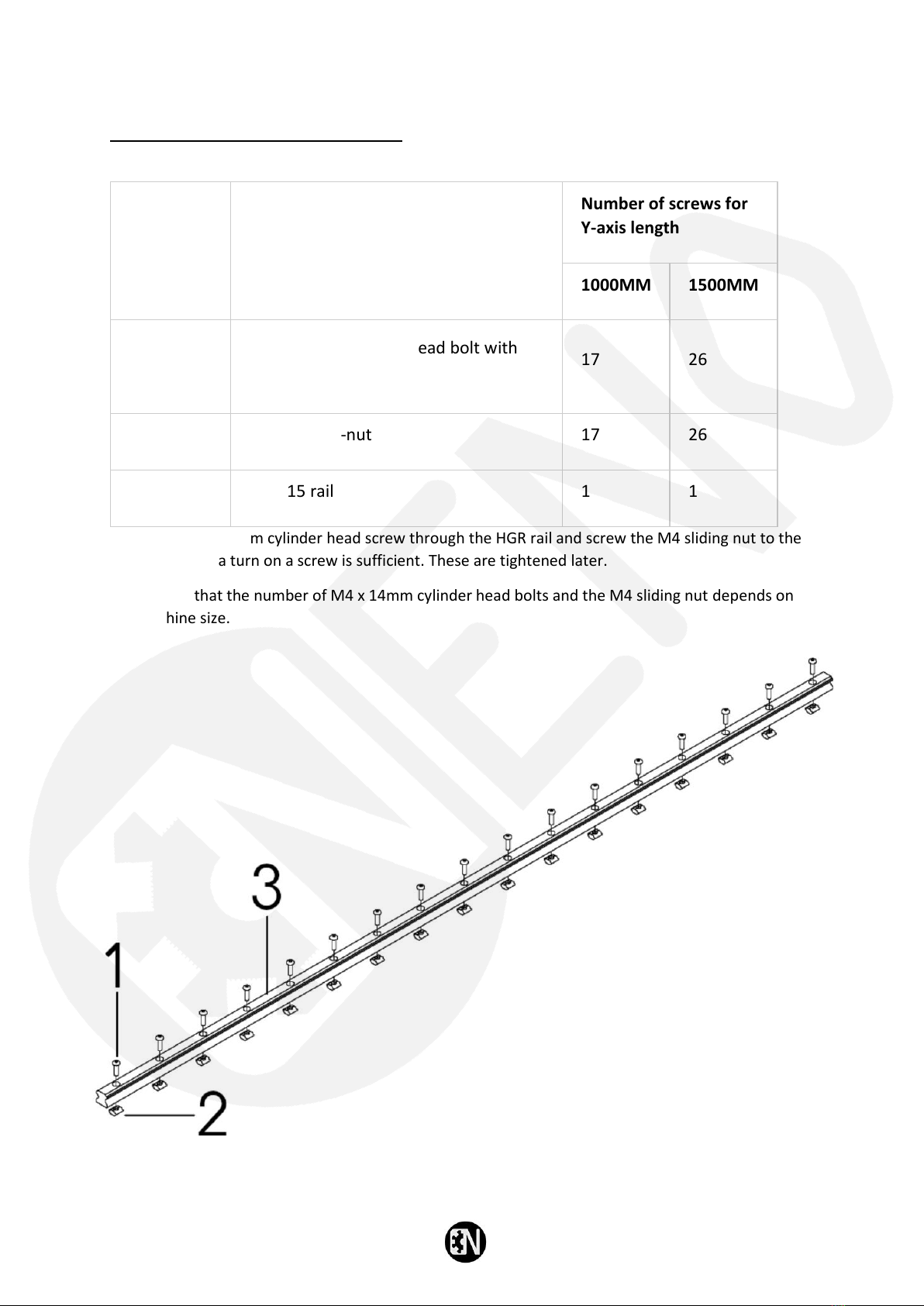
2.1.1 HGR rail preparation
Article Nr.
Description
Number of screws for
Y-axis length
1000MM
1500MM
1
M4 x 14mm cylinder head bolt with
hexagon socket
17
26
2
M4 sliding T-nut
17
26
3
HGR 15 rail
1
1
Insert the M4 x 14mm cylinder head screw through the HGR rail and screw the M4 sliding nut to the
other end. Half a turn on a screw is sufficient. These are tightened later.
Please note that the number of M4 x 14mm cylinder head bolts and the M4 sliding nut depends on
the machine size.

NENO LEADX Ultra Manual
© NENO-CNC Schweiz 2023 Seite | 16
2.1.2 Attaching the HGR rail to the C-beam
Article Nr.
Description
Quantity
1
C-Beam Profile
1
2
HGR 15 rail
1
Slide the HGR 15 rail assembly into the upper channel of the C-Beam profile as shown in the drawing.
Inserting the HGR 15 rails and M4 t-nuts can be difficult. Let another person help you keep the rail
straight while pushing the t-nuts into the C-beam.
NENO LEADX Ultra Manual
© NENO-CNC Schweiz 2023 Seite | 17
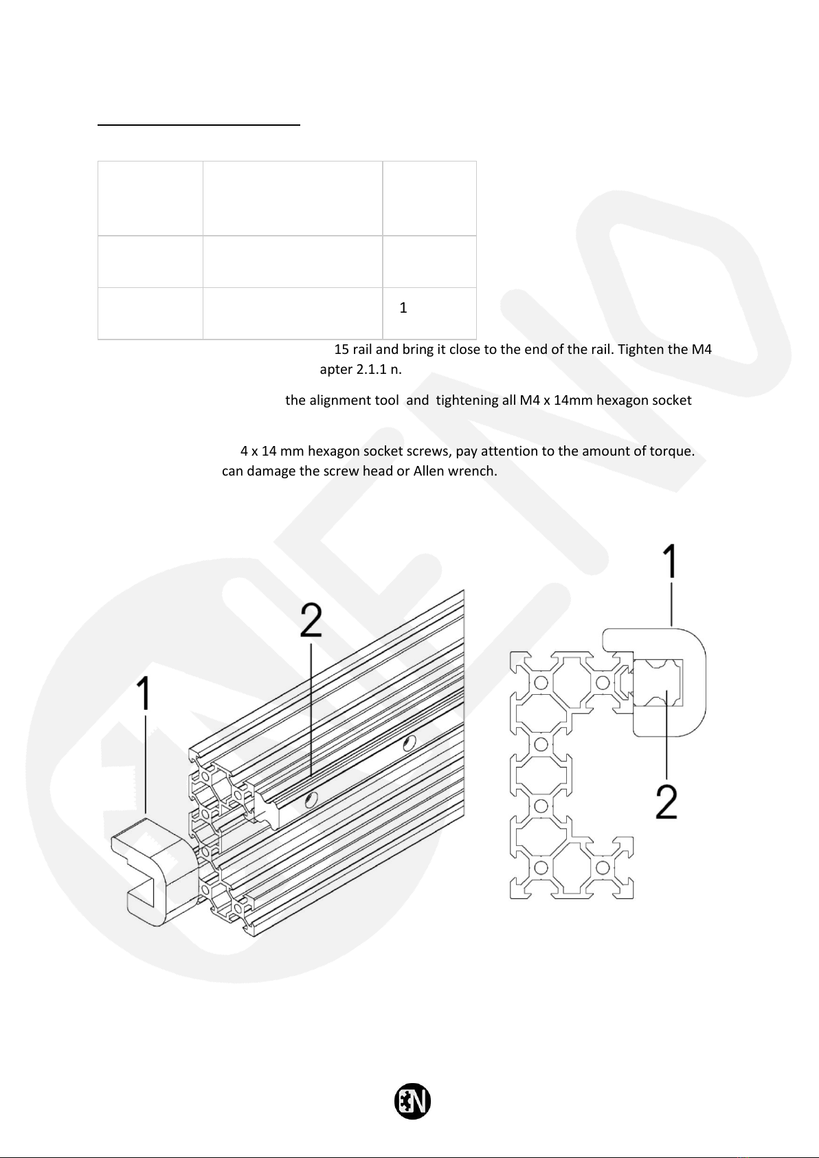
2.1.3 Alignment tool
Article Nr.
Description
Quantity
1
Alignment tool
1
2
HGR 15 rail
1
Slide the alignment tool onto the HGR 15 rail and bring it close to the end of the rail. Tighten the M4
x 14 mm screw pre-assembled in chapter 2.1.1 n.
Repeat the process by moving the alignment tool and tightening all M4 x 14mm hexagon socket
bolts one by one.
When tightening the M4 x 14 mm hexagon socket screws, pay attention to the amount of torque.
Tightening too hard can damage the screw head or Allen wrench.
NENO LEADX Ultra Manual
© NENO-CNC Schweiz 2023 Seite | 18
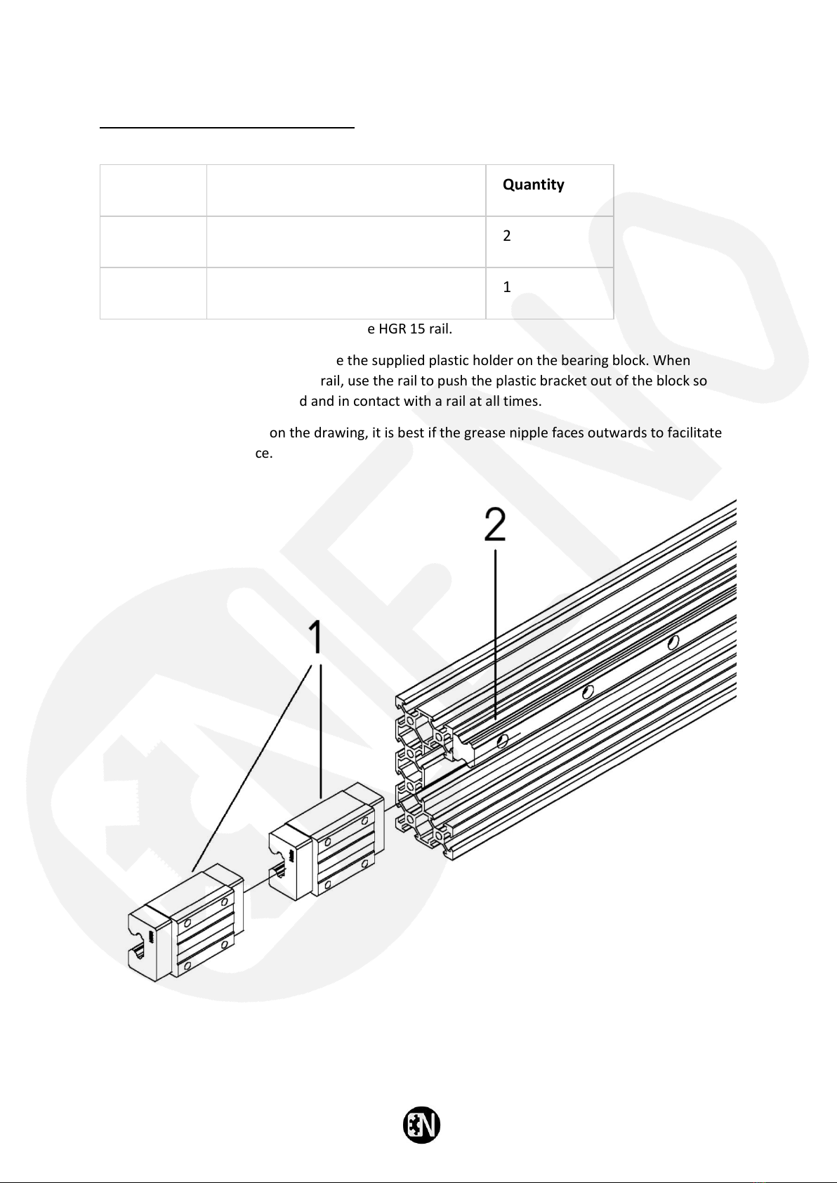
2.1.4 HGH storage blocks
Article Nr.
Description
Quantity
1
HGH 15 bearing blocks
2
2
HGR 15 rail
1
Slide the 2x HGH 15 bearing blocks onto the HGR 15 rail.
To avoid the loss of bearing balls, store the supplied plastic holder on the bearing block. When
mounting the bearing block on the rail, use the rail to push the plastic bracket out of the block so
that the steel balls are preloaded and in contact with a rail at all times.
Although this is not shown on the drawing, it is best if the grease nipple faces outwards to facilitate
access during maintenance.

NENO LEADX Ultra Manual
© NENO-CNC Schweiz 2023 Seite | 19
2.1.5 Insertion of T-nuts
Article Nr.
Description
Number of screws for Y-axis length
1000MM
1500MM
1
M5 sliding T-nut
12
20
2
C-Beam Profile
1
1
Slide M5 T-nuts into the two lower channels on the 40 mm front side of the C-beam profile, as
shown.
Please note that the number of M5 sliding slot stones depends on the machine size taken from the
table above.

NENO LEADX Ultra Manual
© NENO-CNC Schweiz 2023 Seite | 20
2.2 Y-plate
2.2.1 Y-plate and bearing block
Article Nr.
Description
Quantity
1
HGH 15 bearing blocks
2
2
Precision washer M4
16
3
M4 x 16mm screw with flat head
16
4
Y-plate left
1
Insert the M4x 16mm flat head bolts through the M4 precision washer and Y-plate on the left and
screw them onto the HGH bearing blocks as shown in the figure.
When attaching the screws to each bearing, start with the screw in the upper left corner and tighten
this screw by one turn. Now tighten the screw at the bottom left by one turn. Continue like this,
always crosswise, until all screws are fixed.
Table of contents


