Ryobi DP101 User manual

'slool tqoIu 6ur{nq lo; ulebe no{ 1ueq1
'no{ o1 ec!ruos aJnlnl lo eq uec aA os pJeC uo!le4s;6eg Alue.r.reM oql uJnloJ pue mo llg eseald
octruos olqetleJ 'ales lo sleaA Iolua ;prn nof 'pepualul sem ll leLlm to; {uo
pue {pedold autqceu lno{ esn noA;; 'suonneC pue s6uture6 'uoqeledg ales Jol solnu eql ol uoquege eso;c fe6
'autLloeu rvreu lnof 6u;sn elo;aq lenueul s,loletedo oJlluo slql qbno.rq pee.r [;;n1eleC :NOllnVC V
'ocueruJo;1ed eal;-elqnolg 'pa66n.r;o s.reef noA ent6 llfn ]l Jol pelec A;ledo.r6 'f1e1es loleledo pue 'uo4eledo
Jo aspe ,fi1lrqepuedep JoJ spJepuels qbrq s,1qor{g ol peJnlcelnueu pue pelaeutOue uooq seq ssoJd lllfl Meu JnoA
1,0tdo topol l
'ssfud'l'ltuo dor HcNSg lgo^u v eNhng uoJ no^ vNvHr
6L9Z-1Z9-OOB-l le euetl ro^e1 lod';ogedsa
o s?cue4 uo lenupyl lep erdoc eun eossp ls'aluourelos s916u; ue opeJlslutulns so ouensn lop lenuen elsf
' 6 Lgz-g1g-1gg- L ne taledde zalllno^'elou6edse no
asre5ue.4 uolsJo1 eun, p utosoq zene snol ls'oruJnol lsa Jnelestl4n, I ap lenueuJ ec ep asle16ue uolsJol el alnos
'6L92-929
-0Og-l 11ec aseeqd 'qsruedg Jo qcuag urAdoc e paau noA;1 'A1uo qsr16u3 ug pe;gddns sl lenuey\ s,loleledg stql
""1$ll't$,lH31illjj T eo^u

Depth Stop Adjustments......... '..---.-.'..".---...12
Extension Cord Caution................. '.".........13
Self-Ejecting Chuck Key............. '......'...'..-..13
Troubleshooting Guide.. ."........15
Look for this symbol to point out important safety precautions.
It means attention!!! Your safety is involved.
Chuck
Taper
RPM
Swing
112in. (13 mm)
JT33/816
570-3050
10 in. at 1B0o (2S0 mm)
Spindle Travel
lnput
Motor
Height
Net Weight
21l2in. (60 mm)
120V AC, 60H2, 3 amps
114 HP lnduction
29 in. (718 mm)
64 lbs (29 kg)

'lool srql asn ^et! oqh sJeqlo 6uqcru1sut
pue 'uolleJedo e;es Ouqnupluoc .to1 flluenbatl
Mernal pue lenueu s,lolerado oqt oAeS 'ftnfut
;euosred snouos Jo 'looqs lecplcalo 'elg butn;onut
sluoppce ur llnsal uec A;dutoc ol oJnlteJ 'lenueul
slLll u! paulBluoc 'c1o 'so;nl f1ales 'suotlcnJlsut
gle rtlelelduoc puelsJopun pue flqonoloql pee.t
eneq nof lrlun lool stql eletedo ol ldueDe lou oC
:CNINUVM V
'lcor.ls lBcrJlcolo
ol polelor suo4necerd rleles letuJou lle 0urp;one
oruosqo
v
:9NINUVM
'syed luaruece;der rqofg ;ecnueprlluo asn 'buprrues uaq6
'lredel JoJ JoluoC oc!ruos pozgoqpv lqoIu lsoJeou rnoA o1 lool aql urnler nof 1se60ns o^ ectruos Jol 'uelcluqcol
ectrues peglenb e fq fluo peu.uo;red oq plnoqs pue trelsAs eq11o e6pel/v\oul pue oJec euleJlxe serrnber Ou;crrueg
INVIUOdI,\II
SNolrVCO] dlM
Nt3Sn UO N|VU Or
fsodxf roN oo
'luaudlnbe aLll Jo ooueusluleur .ro uorleledo eql ol lelrn suorlcrulsur Jo uoqeuJJolur 1o nof sasrnpv :oloN
'&n[ut
;euosted pue lcoqs cppalo 'oJlJ Jo lsu aql acnpor ol suorlnecord fie1es aLil Mollol sfenn;y 'sJaLllo ol
lo llaslnoA o1 Lrnfur leuosred ro e6eurep {pedord ur llnsoJ Ieu 0uturern [1e;es e [eqo ol aJnllel
:NOIINVC v
'tunlut lBuosJed pue lcor.{s cr4cele 'eJu lo lsrJ or.,ll ocnpoJ ol suorlnecaJo Aloles oql
/nollol sr{erv1y 'slaq}o ol Jo JlasJno{ o1 funlur snouas ur ilnsoJ uec oururern f1e1es e feqo ol oJnllel
:gNlNUVtrA v
'&nfur ;euosled pue )por.ls culcalo 'erg 1o lsu eLll ocnpal ol suoqnecoJd Agales eql
MOlloJ s{err,1y 'sJoqlo ol Jo lasJnof of funtur snouQs ur llnsal ;;rr'ir oururern r{le;es e ^eqo ol oJnlreJ
:uf9Nvo v
sqde:Oo1crd ro sloqurfs Jotllo Lllrii\ uotlcunluoc ut posn aq [ey1 'uognec ro 'Ourulervr le6uep selecrpul
:'log l,lt^s lu=t'lv AISlvs v
9NtNV3Ult 108UUAS
'soJnseou uoguenerd luoppce
ledo.rd Jol solnillsqns lou ale enr6 Ieql sbururem Jo suolpnJlsur oLll lebuep fue eleutu.ttlo sonlasuleql
{q 1ou op sburu:ein fgeles eq1 'burpuelsJopun pue uo4uape Inlorec rnof eruesep 'uoql qlrn suoqeue;dxe
eLll pue 'sloqr.u{s fieles eq1 's.re6uep elqrssod ol uorluol]p rnol lce.rge ol s! sloqu{s A1e1es 1o esodrnd eq1

READ AND UNDERSTAND ALL
INSTRUCTIONS
1 . KNOW YOUR POWER TOOL. Safe operation of this
power tool requires that you read and understand
this operator's manual and all labels affixed to the
tool. Learn its applications and limitations as well
as the potential hazards.
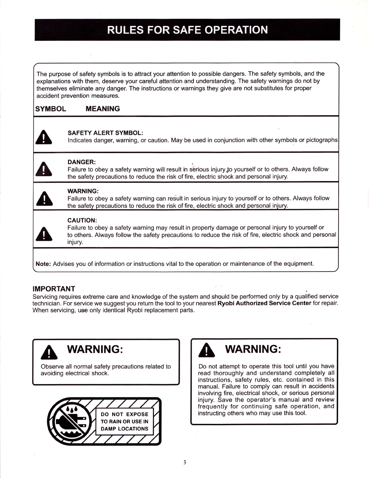
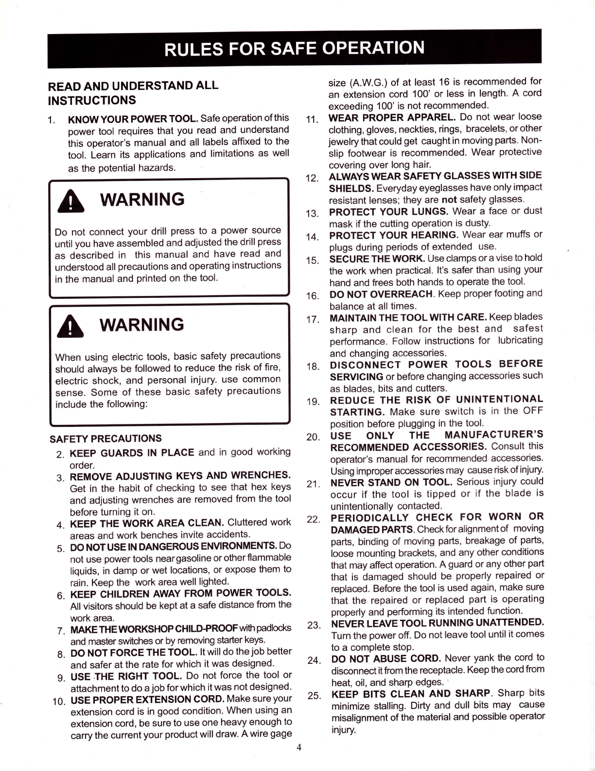
A WARNING
When using electric tools, basic safety precautions
should always be followed to reduce the risk of fire,
electric shock, and personal injury. use common
sense. Some of these basic safety precautions
include the following:
SAFETY PRECAUTIONS
2. KEEP GUARDS lN PLACE and in good working
order.
3. REMOVE ADJUSTING KEYS AND WRENCHES.
Get in the habit of checking to see that hex keys
and adjusting wrenches are removed from the tool
before turning it on.
4. KEEP THE WORK AREA CLEAN. Cluttered work
areas and work benches invite accidents.
5. DO NOTUSE lN DANGEROUS EM/IRONMENTS. Do
not use power tools neargasoline or otherflammable
liquids, in damp or wet locations, or expose them to
raiin. Keep the work area well lighted.
6. KEEP CHILDREN AWAY FROM POWER TOOLS.
All visitors should be kept at a safe distance from the
work area.
7. MAKE THE WORKSHOP CHILDPROOF wih padlocks
and master switches or by removing starter keys.
8. DO NOT FORCE THE TOOL. lt will do the job better
and safer at the rate for which it was designed'
9. USE.THE RIGHT TOOL. Do not force the tool or
attachment to do a job for which it was not designed.
10. USE PROPER EXTENSION CORD. Make sureyour
extension cord is in good condition. When using an
extension cord, be sure to use one heavy enough to
carry the current your product will draw. A wire gage
13.
'14.
15.
16.
17.
11.
12.
18.
19.
23.
24.
size (A.W.G.) of at least 16 is recommended for
an extension cord 100' or less in length. A cord
exceeding 100' is not recommended.
WEAR PROPER APPAREL. Do not wear loose
clothing, gloves, neckties, rings, bracelets, orother
jewelry that could get caught in moving parts' Non-
slip footwear is recommended. Wear protective
covering over long hair.
ALWAYS WEAR SAFEW GLASSES WITH SIDE
SHIELDS. Everyday eyeglasses have only impact
resistant lenses; they are not safety glasses.
PROTECT YOUR LUNGS. Wear a face or dust
mask if the cutting operation is dusty.
PROTECT YOUR HEARING. Wear ear muffs or
plugs during periods of extended use.
SECURE THE WORK. Use clamps or a vise to hold
the work when practical. lt's safer than using your
hand and frees both hands to operate the tool.
DO NOT OVERREACH. Keep properfooting and
balance at alltimes.
MAINTAIN THE TOOLWITH CARE. Keep blades
sharp and clean for the best and safest
performance. Follow instructions for lubricating
and changing accessories.
DISCONNECT POWER TOOLS BEFORE
SERVICING or before changing accessories such
as blades, bits and cutters.
REDUCE THE RISK OF UNINTENTIONAL
STARTING. Make sure switch is in the OFF
position before plugging in the tool.
USE ONLY THE MANUFACTURER'S
RECOMMENDED ACCESSORIES. Consult this
operator's manual for recommended accessories.
Using improperaccessories may cause riskof injury.
NEVER STAND ON TOOL. Serious injury could
occur if the tool is tipped or if the blade is
unintentionally contacted.
PERIODICALLY CHECK FOR WORN OR
DAMAGED PARTS. Check for alignment of moving
parts, binding of moving parts, breakage of parts,
loose mounting brackets, and any other conditions
that may afiect operation. A guard or any other part
that is damaged should be properly repaired or
replaced. Before the tool is used again, make sure
that the repaired or replaced part is operating
properly and performing its intended function.
NEVER LEAVE TOOL RUNNING UNATTENDED.
Turn the power off. Do not leave tool until it comes
to a complete stoP.
DO NOT ABUSE CORD. Never yank the cord to
disconnect it fom the receptacle. Keep the cord from
heat, oil, and sharp edges. '
KEEP BITS CLEAN AND SHARP' Sharp bits
minimize stalling. Dirty and dull bits may cause
misalignment of the material and possible operator
injury.
20.
21.
22.
A WARNING
Do not connect your drill press to a power source
untilyou have assembled and adjusted the drill press
as described in this manual and have read and
understood all precautions and operating instructions
in the manual and printed on the tool.
25.

'po^lo^u! s! Iloles
rno1 iiiuolluolle supou ll 'suolmeoe.rd fle1es luelrodur; lno lurod o1 loqufs s!l'.ll Jol loo'l
'splolqs opls t{llrvt sossBlo r{1e;es pJepuels lo sasselEor(o leno esn
rol IseW Aleles uolsln opl6 puauuocol aM'popoou uoqtn ploltls aceJ llnl e
pue splolqs oprs ql!/t1 sesse;6 r{1e1es.ro se166o6 fieles leem sr{em;e 'uogeredo
lool.ramod 6u;uu16aq oJolog 'e6eurep efie elenes u! ilnsal uec qc;qm 'ser{e
tnor{ o1u; urnoJql 6u;eq slcafqo u61e.ro1 u! ilnsol uPc llup fue 1o uollelodo oql
:CNINUVM
.sepryed cldocso.rcrur lno lell4 o1 peuOrsep {lercads oJe leql slseul lsnp asoql sB qons 'lueudtnbe
[1e;es peno1dde qU/rA llo/v\ pue 'eoJB palel!]uon llal e ul lJoM :slecltuaLlc osaLl] o1 elnsodxa lnof
ocnpoJ oI .lJo/vt;o edfi slr.ll op nof ueyo /'Aoq uo Ou;puadap 'souel selnsodxe asaLD ulo4Isu lnoA
roqurnl paleo4- A1;ectutaqc ulo4 ulnlulolqc pue cluase .
pue .slcnpold Lruoseut Joqlo puB luouloe pue slcuq uoJl ecllls eull;e}s&c .
'sluted poseq-Peal uo4 PBsl .
:oJe slecllrjaqc osaLll
1o saldLuexe auos 'uJeq a^4cnpoldel Jeqlo ro slcalap qplq lacuec osnBc ol u oul sleclu.lotlc suleluoc
seq;n;1oe uo4crulsuoc leqlo pue '6ur;1r.rp '6utpult6 '6utmes 'Outpues ler'lod Aq paleeJ9 ]snp oulos
:9NINUVA
'osle suolpnJlsul
osorll u,oql uBol 'lool slql ouool'uos ueol
nof ;; 'sresn Joqlo pn4su! ol esn pue {puenbe:;
r.uoql ol retau 'sNollcnulsNl 3sfHI 3nvs
'qted lueutaoe;de.t
leclNep gor{g {uo asn 'reluac aJ!ruas pozuoq}nv
lqo^U e le epeur aq plnoLls ''lVClNVHC3lttl
uo'lvclulcS'I3 ufHrSHtn'sulvdSu llv
'6uruels leluoptcge plole ol lt Ourceuuocslp
orotaq lJo HcrlMs Nunr s^vM]v
'Joluo eolntos Pezuoqlne ue fq
peoepa solpl!/ri\s e^ocalop o eH 'JJO ONV NO ll
NUnlroN s oo HcJl ls Jl 10013sn toN oo
'uolleclpetu Jo
loqocle 's6nlp lo acuongul eql Jopun allq/'A Jo pal!l
uoql lool rervrod e eleledo lo^aN 'lU3'lV AVIS
'lool ueals
ol sluonlos fue lo 'slcnpo.td poseq-ulnalolled
'eu1;ose6 'sp!nU oIeJq osn lonoN '6utuee1c
uoLl/v\ qlolc ueele e esn s^er'rr1y Es\r3u9 oNv
'lto l,\touJ 33uJ oNV'N\E'IC rUO rOOr d3fy
'ilq aql ul
palOuelue ouooaq [Br-u ler]l 'cle 'Jleq 6uo1 fuay'la[
'bulrjlop asoo;Iue ute4seu 'ilq eql ulo.4{erne spueq
deey'v3gv yuom t{oul Avi v soNvH dSfv
'18
'zt,
'0e
'82
'LZ
'62 '92

a
aAlways wear eye protection.
Always disconnect the tool from the power source
when setting up, adjusting, or changing accessories.
Do not wear gloves necktie, or loose clothing. Always
clamp workpiece and brace against column to
prevent rotation.
Use recommended speed for drill accessory and
workpiece material.
Be sure drill bit or cutting tool is securely locked in
the chuck.
Be sure chuck key is removed from the chuck before
connecting to power source or turning power ON.
Adjust the table or depth stop to avoid drilling into
the table. Shut off the power, remove the drill bit,
and clean the table before leaving machine.
Do not connect tool to power source or operate until
it is completely assembled and installed according
to the instructions.
lf any part of your drill press malfunctions or has been
damaged or broken, do not operate until the part is
properly repaired or replaced.
Never place your fingers in a position where they
could contact the drill or other cutting tool if the
workpiece should unexpectedly shift .
Never use your hand to hold the object while drilling.
Always clamp the object tight on the work table or
use a drill vise to prevent accidental injury.
Never perform any operation by moving the head or
table with respect to one another. Do not turn the
motor switch ON or start any operation before
checking that the head and table lock handles are
clamped tight to column and head and table support
collars are correctly positioned.
Before engaging the power switch ON, make sure
the belt guard is down and the chuck is installed
properly.
Lock the motor switch OFF when leaving the drill
press. Do not perform layout, assembly, or set-up
work on the table while the cutting tool is rotating,
switched on or connected to a power source.
Firmly clamp or bolt your drill press to a work
bench or table.
SAVE THESE INSTRUCTIONS. Refer to them
frequently and use to instruct other users. lf you loan
someone this tool, loan them these instructions also.
GROUNDING INSTRUCTIONS
ln the event of a malfunction or breakdown, grounding
provides a path of least resistance for electric current to
reduce the risk of electric shock. This tool is equipped
with an electric cord having an equipment-grounding
conductor and a grounding plug. The plug must be
plugged into a matching outlet that is properly installed
and grounded in accordance with all local codes and
ordinances.
Do not modify the plug provided. lf it will not fit the outlet,
have the proper outlet installed by a qualified electrician.
lmproper connection of the equipment-grounding
conductor can result in electrical shock. The conductor
with the insulation having an outer surface that is green
with or without yellow stripes is the equipment-grounding
conductor. lf repair or replacement of the electric cord or
plug is necessary, do not connect the equipment-
grounding conductor to a live terminal.
Check with a qualified electrician or service personnel if
the grounding instructions are not completely understood,
or if in doubt as to whether the tool is properly grounded.
Repair or replace a damaged or worn cord immediately.
This tool is intended for use on a circuit that has an outlet
like the one shown in Figure 1. lt also has a grounding
pin like the one shown.
@
o
@
GROUNDING
PIN COVER OF GROUNDED
Fig. 1 ourLET Box

'socold)lloM azls lueJaJJlp elepoultlloccP ol JopJo ul
uunloc oql uo Aglecq.ran se;6ue snouen 1e peuo4tsod eq
ol slqe pue uunloc aql uo papoddns ocelns lo^ol 'lell
olqel IroM
'pollpp oq ol st aloq e qclq^ olu! lcafqo aq1
ece;d1.to1y1
'llaq e;o sueeu [q
Ie;;nd rolout oql ^q uo^trp sr Ae;1nd elpu;ds eq1 'e1pu;ds
erll Oullelo.t .ro; elq;suodser {a11nd lecluoe 'penool6 y
fe;1n6 elpu;dg
'paqcepe st lcnqc eql qclqm uodn geqs 6u4e1ol aq1
elpu;dg
'uolleledo 6u;11r.rp e ul aloLl eq11o qldep
eq1 bugeln6er pue ecaldllorn oLll olu! llq pue lsnqc oql
buuervrol.ro; e;qtsuodsou 'UeqS poal oql sP u/v\oul oslv
[!no
A;elerncce seloq eOle; 0ut11uP .to;
eprn6 e se soruos ler{l ecetd}tol e ul pollpp oloq lleuls V
otoH lolld
'ltoq
B Jo sueotu {q {e;;nd elpulds eq Ou;n;lp lo; elqlsuodse.t
pue Jolotu etll Iq ue^Up {e1;nd lecluoc 'penool6 y
{e;1n4 rotoy\l
'uorlelado
6ur11;.rp e 6upnp llq pue lcnqc eLll re^ ol o1 lole:edo
aql molle qclq/n lltnb eq1 ol paqcene solpueq earql
salpueH poal
'ecetd4om oLll olu!
pare^^ol sl 1q llpp ot,ll Wtq^ qlun ocrol pue paeds eq1
pooJ
'elpurds pue';;tnb'loloul
oql sosnoq qcrLl/v\ uuinloc oql lo do1 aq1 1e ,{lquesse eq1
peoH ssord lluo
'uoqeredo 6ur11r.rp e ut posn lool Outunc polnll
llg lluo
'uotleledo 6u11gup e ul aloq eq1;o qldep eql
loJluoc ol roleredo oql smolle qclqm loJluoc luaulsnlpy
dols qtdoO
[lqutesse peeq ssetd ;;t.tP
pue olqel Uo^ aql syoddns leql poJ lelnctpuedled e6le'1
uunloc
'>lcnqo aL[ uosool pue ue1q64 ol pasn Ael pauu y
Aey lcnqg
'ilq llup or-ll
soJncesleql elpurds eqlJo pue eqlle ectnep 6utdue;c eq1
rcnqc
'uolleedo 6ut;;t.tp e ut olotl sql tuo4 pepeJ1xa leuoleu oql
dtttc
'ace;.tns ;enel fplnls Jeqlo Jo dolqcueq
e o1 ssard llpp otll soJnces 1e4 e1eld:eln6uepel e6:e-1
ose€

Know Your Drill Press
Motor: Equipped with industrial duty rated, 114 HP
induction motor for long-lasting, smooth performance.
5 Spindle Speeds: 5 spindle speeds allow you to drill a
wide variety of materialfrom wood to plastic to metal'
Drill Ghuck: Standard 3-jaw type, quality drill chuck and
self-ejecting chuck key included.
Self-Ejecti n g G h uck Key : Key automatical ly ejects from
the chuck to prevent accidentally starting drill press with
key still engaged in chuck.
Spindle: Spindle is supported by quality ball bearings
to ensure accuracy.
Depth Stop: Adjustable position locking depth stop for
accurate depth measurement and repetitive drilling.
Chuck Key Storage: On-board chuck key storage keeps
key within easy reach.
Worktable: Rotating, tilting, crank operated work table
for added versatility. Slotted worktable and base allows
easy application of clamping devices.
r
1,,-{
| ls^
L_ 12+ 14
t--
3
\, t_
Fig.2
1. Drill Press Head Assembly
2. Column
3. Table Assembly
4. Table Lock Handle
5. Base
6. Feed Handles
7. Chuck Key
8. Chuck Key Storage
9. BevelScale
10. Depth Stop
11. On/Off Switch
12. Chuck
13. Table Height Adjustment Handle Crank
14. Motor
15. Depth Scale
16. Gear Rack
17. Belt Tension Knobs
18. Pulley Housing

(ur'iroqs 1ou) lenueyl s,loletedg '6;,
slpuBH los alecs '81
Jelpc ese€ 'z!
rcnqc'9t
relloc uulnloc'91
Jeae ulJoM'tl
Iceu lPoe 'el
alpuBH luerc ogeL'2,
(nrrul) rlouarM xsH '1.
(t) sttoe xoH 9Z't gy\t '0 t
/v\oJcs peoH ued 9l l '6
qouy 6u;snog Ae11n6 'g
fey pnq3'2
(t) setpueg peol'9
ose8'9
olpuBH tco'] olqel't
flquessy olqel't
utLlnloc'z
rtlquessy pesH 'l
'funfut alenes lclgu! ol luolcgns sl puooas
e Jo uo[oe4 sseloJec B leL[ JaquouJau 'ssoleJsc nof
oleu ol sse.rd ;;r.rp lnol qyvr fipe1;1ue;^ olle lou oO
:CNINUVM V
'lool aql
esn ol Ourlduage oJoloq pece;de.r aq plnoqs ped
6ulssrru.ro pe6eurep r(uy '6utddtqs 6uunp poJJncco
seq e6eleeJq ou oJns olBul ol sped aql lle auluiexf
'lool eql alquosse ol bundueBe aloloq lt utelqo
ol Jalpep rno{ peluoc 'ped e Outsstttt e:e nof ;;
'f;quesse o1 peeco.rd 'popnput ueoq e^eq syed 1;e;1
'1sr; sped eql6ulsn sped eq1 lle pegttuapl
eneq nof lllun leueleui 6u;1ced aql pJecstp lou oO
'uoueo buqddlqs oql uo4 syed 11e olouter I11n;ele3
'9
'v
,e
'z
.L
e'o!J
.Z\.
//----''\ 1-.r'LL
R(Oi./
'\://'
m---h -'zl
/d,r.J
\ t-
\//
sluvd fsoo'I
00aa \z
I
z\
Anlut ;euostsd snoues
ur ilnsoJ plnoc Outurern stql paoq ol aJnlleJ 'butsstut.to
pa6eu"rep ere syed Aue;r qcyvrs uo uJnlJo 'p.too lemod
erll ul 6nd 'ssald lpp ol.ll elquasse ol lduege lou oO
:CNINUVM V

1.
2.
TOOLS NEEDED FOR ASSEMBLY
#1 and #2 Philips Screwdriver
Adjustable Wrench
Hammer or rubber mallet
Place the base on a flat surface and assemble the
column to the base using the four M8 hex bolts.
-it t
Locate the worm gear and feed the Dishaft through
the hole in the the table assembly as shown in
Figure 4.
lnsert the D-shaft through the hole in the table crank.
Align flat side of shaft with the set screw on the table
crank handle. Tighten set screw using the 4 mm hex
wrench.
Feed the gear rack through the slot in the table
assembly so that the teeth are facing out and the
longer smooth end faces up. The worm gear should
engage the gear rack.
Using both hands, slide the entire assembly onto
the column until the bottom of the gear rack is
positioned against the base collar. See Figure 5.
4. Slide the column collar, bevel side down, over the
column until the beveled side engages the beveled
end of the gear rack. Tighten the set screw in the
collar using the4 mm hex wrench. See Figure 6. Do
not overtighten
NOTE: Table should be able to move side to side.
Do not overtighten set screw.
Fig.6
Locate the support lock handle. lnsert it into the
threaded hole at the rear of the table assembly and
tighten by hand. (* 6il' ''17);
Position head assemblyrupside down on a level, flat
surface. Position chuck on spindle. Chuck should
be fully opened to avoid damaging jaws. Using a
scrap block to protect the chuck, firmly tap the chuck
into place using a hammer.
Lift head assembly on column with the spindle
positioned over the table. Slide head assembly down
as far as it will go. Tighten the two head set screws
with the 4 mm hex wrench. See Figure B.
5.
6.
3.
7.
set screw
worm gear
\
i9m=
,/-
crank handle
Fig.4
1..= ') - base cottar
10

II
alpueq )uelc elqel
'{qloottts
sonou geqs egputds oql leql oJnsse ol )peLlC
'luouiA^ou U/IAOP Pue
dn qloor.r.rs ornsse ol lo)oelq olqel aql lcoq3
'fuesseceu se
aJe/v\pJeq buqunoul eq ualqOuet pue lsnfpy'119
paqcyns sr JolouJ ol.ll uaLl/v\ uo[eJqlA Jo] lcaLlc .
:0urr,iro||ol aq1
Icorlc 'ace;.tns Aptnls e uo polunoul {;elncas acug
'9tr an617
eos 'olpueq lcol aql uelq6n-el pue uo4tsod poJlsap
aql u! olqel aLll uolllsod 'll sJo/v\ol asl/rr\Icolclolunoc
:alqel aql sosreJ est/v\IcolC 'alqel aql osleJ Jo Ja/v\ol
ol alpueq luerc olq4 aql olelou 'olpueq lcol olqel aLll
uosool pue pueq auo Llltm alqel eql plotl 'olqq lsnlpe o1
lt{6!oH otqel aql 6u;lsnJPY
tNltrilrsnrov f't8vr
'scJnos-lol od eq ulo.tl
sserd 1;up aql lcouuocstp 'luou4snfpe ato;eg
:CNINUVM
,tnlut snoues e;qtssod pue Oupels
le1uaploJe urilnseJ pgnoo fldutoc ol aJnlPJ 'e1e;dutoo
sr {;quresse ;;1un Alddns rcrnod o} pouuoc lou oO
:CNINUVM
'qcuaqllo/v\
e o1 pedure;c A;tsea aq uec ]eql pJeoq butlunou
e ol ,{[ueueured il uolse] nof 1eq1 popueululocoJ
sr 1r 'uoqectldde elqeyod e ut posn aq o1 st sseld
glpp rnof 1 'dol Jolunoc Jo qeuaqlJol 'puels IJo/v\
e se Llcns ocelns fp.rnls e uo {;elnces sseld ;;t.tp
rnof lunour 'oseq oql u! saloq pellup-etd aq1 6utsl
'qnq eql ul soloLl popeeJql aLll
olur ueLllOunnarcs [q selpueq paol aoJLll ot]l WBUV
'6
'8

BevelAdjustment
Your drill press is equipped with a tilting table that allows
you to drill angled holes. The table can be tilted left or
right, from 0-45 degrees.
To tilt the table, first loosen the table lock handle. Then
loosen the large hex bolt located underneath the table.
See Figure 71. Use the bevel scale to tilt table to the
desired angle, then tighten hex bolt. Retighten the table
lock handle.
Table Rotation
When drilling large objects it may be necessary to swing
the table out of the way. Simply loosen the table lock lever,
rotate table, and retighten table lock lever.
Note: When using the base as a work surface, the
workpiece must be clamped securely to the base.
DEPTH STOP ADJUSTMENT
Where a number of holes are to be drilled to exactly the
same depth, the depth stops used are as follows:
Loosen scale set handle located on the feed shaft
assembly, rotate spindle depth as desired and tighten scale
,t
/ Tohold a stationary depth, loosen scale set handle and
/ turn feed shaft to lowest point, then rotate spindle depth
/ to desired depth and retighten scale set handle. This
I will hold the spindle assembly stationary at desired
\ oeptr.
CHANGING SPEEDS
The spindle speed is determined by the location of the
belt on the pulleys in the pulley housing. The reference
chart located inside the pulley housing shows the
recommended speed and pulley conflguration for each
drilling operation. To change the pulley configuration,
refer to Figure 14 and proceed as follows:
Loosen the two belt tension knobs located on either side
of the head assembly. See Figure 2.
Push the motor assembly toward the front of the head
assembly to loosen the drive belt.
Open the pulley housing cover and reposition the belt
according to the speed chart. Close the housing cover.
Push motor firmly back to position assuring drive belt is
tight. While holding tension on motor, retighten the two
belt tension knobs securely. See Figure 2.
speed chart
-. ---.- _
4<-
-)^)
scale set
handle
,\-->
-\ ^(
bevel scale
Fig.12
\ set handle. See Figure 13.
t2

€I
finlur puosred snopos u!ilnsal p;no butulern slql peoq
ol aJnlpl 'sserd 1pp oql uo 6u;tunl aJolaq ooEJns olqel
ol4 uro4 Ae>1 >pnqc o(fl a oual ol Fquloual v(emy
:CNINUVM V
ftnfur
;euosted snopas ul ilnsoJ gnoo bululer'a sql pootl ol
arnpel 'uo11ecq sJes e u! oJols pue Ael lcntp o ouial
s{ervry'pap4ord Ae1 pnr-p 6uncef+1es eq {uo es1
:gNINUVM
'uolleFsu! uJo/r^Jo rp pue ser'ir pesodxe.ro esool.tolil pedsut
'pJ@ uotsuoye fue 6usn oJoJag 1e1cef s,p.too otll uo,,'V'114'
s.ragel eq1 Aq poleclpul sl slLll 'osn opslno rc; peu6sep q leL;1
pJoo uosuayo ue osn sooplno pol e q1m 6ut4tom uaqg
'posn oq plnoLls spJoo
pelo1Je[popunot Alug 'pJ@ uosuayo ue q paltnba ozls olm
'esn 6uunp suoqcnJlsqo Jeqlo Jo 's;oo1 'ecetd4tor,l
uo lq6nec la6 1ou llll ll leql os pJoc aLll uolllsod
'eere 6ut1.toiv\ otll lo Jeap ploc uolsuauo eq deey
:gNINUVM
pou,nr oq rou ^", ,"li"JlT#i:"J.iT llHr'ii':r""1:
'uo;1eledo Ouunp ponotroJ srfe>l er-,llJl 'uo sseld llpp oql
uJnl ol ace;d ut aq lsnu fe1 aq1 'uo pauJnl 6u;aq uo4
sserd 1;up erll slueneld [e1 qclms aql'po^oueJ uotlM
fe1 qclrins goiuo ue qlrm peddrnbe st sseld llpp rno1
A3v Hcrli^s llo/No
Alqutasse peaq sseld llpp eql uo polecol ebe.rols {a1
Icnqc pJeoq-uo aql ul ll ece;del sAer'l;e fe1 pnqc
aql qll/v\ poLlslull ele nof ueqM 'lcnqc oql uasool
ol os!/r^lcolcJolunoc '1cnqc eq1 uelqon ol esl/vDlcolc
- fey eql alelou 'uelr]6rl Ael pepeol 6upds eq]
loel lllm no1 'oloq lcnqe oql olul Ae1 aql qsnd fe>1
lonqc eql6utsn lcnqo eql uelqbu.to uosoolollapJo ul
'uo peulnl sl
sserd llup oql fuolf S lcnqc or.,ll ulo4 panouel stfe>1
lcnqc eql leql saJnsuo Ie1 >1cnqc 0uncefe-;|es aq1
Afv vgnHc eNlrc3rl'1llls
tlnujlultu oql ouluualop ol ueqJ oql asn 'lervrod p ssol pue
6uneer4ano ut ougnsa 'eoepn au;| ut do.tp e osnH) ll!/v\ pJ@
pozrsropun uv'/rt\eJp llrr^ lool oqluoJJnc oqq elpueq o1 ^ycedec
oL0 seq lPql pJOo uolsueyo ue OSn ol OlnS eq 'eOlnOs:er'nod
e uo4 oouEslp opaaplsuoo P le pol rcmod e Ousn ueq6
Nolrnvc ouoS NOISNf rxll
'lrncrrc dure 97 - e6neb Z! uo posn +*
0t z, vt 9t 9L ,00 t
z, n, ,, 9t 9r 9L ,09
v, vt 9t 9t 9L 9t ,92
('C'm'V) azts arlm q$ue1 p.tog
0'91- r'zt 0'zl - ,'L 0'L - l'9 0'9 - 9't n't, - t'z o'z-0 (eleld etep lool uo)
6utler eledtuy**
'[1ddns lennod aql looqc olqnoP
'lallno ue olul pe60n1d uaLl/v\ oleJado lou seop
1oo1 rnof ll 'leoqJalo llt/rl Joloul aLll pue lernod ;o
ssol e asnec llrrvr dorp ebel;on lequelsqns V '(CC)
luaJJnc lcoltp uo lool sll.ll eleledo lou oO '(luelnc
ploqosnoq ;eutou) fluo 3y 'zH 09 'sllo^ gZL sl
1eq1fgddns rervrod e ol pa]cauuoc eq {uo plnoqs ll
'rolour clJloole lllnq uolslcoJd e seq sseld ;;t.tp lnol
:CNINUVM
-J-1- 9r'6u
F\
\r{ey qcyng 'finlut ;euos.ted snouas ulllnseJ plnoc Oululem sltll
paoLl ol oJnltel 'uot1sod JIO eql ul sl qclms aql
pue Alddns lernod aql ruo4 pe66nldun st sseld 1;tlp
aql erns aleu 'lueullsnfpe fue Oulul.tol.led elo;eg
:CNINUVM V
NOIIVUIIUOI N I lvull Nlle

A WARNING:
Do not attempt to operate this tool until you have
read thoroughly and understand completely all
instructions, safety rules, etc. contained in this
manual. Failure to comply can result in accidents
involving fire, electric shock, or serious personal
injury. Save this operator's manual and review it
frequently for continuing safe operation and
instructing others who may operate this tool.
chuck ti=
kev \ Q-=
\Z:
n\ -
;/,>eF
f/xY" /\-=
d (/ I
) t<ey rrote
/r,o.,,
A WARNING:
Before attempting to use your drill press familiarize
yourself with all operating features and safety
requirements.
OPERATING YOUR DRILL PRESS
1. Using a C-clarnp or similar clamping device, secure
the workpiece to the work table. To protect the top
surface of the workpiece, use a piece of scrap
between the clamp and the workpiece.
c-clamp
\
Fig. 16
Select the proper drill bit based on the size hole
desired. For large holes, drill a pilot hole first, using
a smaller diameter bit.
Loosen the chuck by inserting the chuck key into
the chuck and turning the chuck key
counterclockwise. See Figure 17.
4.
5.
Place drill bit between the jaws of the chuck and
tighten chuck by turning the key cleckwise.
Set quillto desired depth. See page 11.
6. Make sure the work table is free of all loose objects
and that the bit is not in contact with the workpiece.
7. Plug electrical cord into power supply and turn switch
ON. Make sure spindle rotates freely.
g. Slowly lower drill bit into workpiece. Do not force
the bit, let the drill press do the work.
g. Once the hole is completed, allow the spring-loaded
quill to return to its normal position. This will
DRILLING TIPS
lf the hole is large, it's a good idea to drill a smaller pilot
hole before drilling the final one. Your hole will be more
accurately positioned, rounder, and the bits will last
longer.
lf the hole is deeper than it is wide, use coolant and
back off occaisionally to clear the chips.
As you step up in drill size, you will need to reduce the
spindle speed.
lf drilling a through hole, ensure that the bit will not drill
into the table after moving through your work.
WARNING:
When servicing use only identical Ryobi
replacement parts. Use of any other parts may
create ahazard or cause product damage.
2.
3.
t4

SI
'il a6ed aos 'aceldilo/tt
durelc-er Jo/pue Uoddns lcoqC
Apedo.td
peduep.ro pepoddns lou acetdl.to1111 suosool Uoddns acetd1.to11
'7y e6ed eas 'uolsuel leq lsntPY
ecetdltolr
dure;c-er Jo/pue l.toddns lceqC
uorsuol 1;eq ledotdttlI
arnssard pae] enlssocxf ecald>Uor'rr ut spulq llq llUO
Jaluac
oo!ruos pezpoqpv qoAg 1ce1uo9
'gp ebed ees ,{Uedod )Pnt.o lp1sul
'ytr e6ed aeg fpedold 1q ;;e1su;
1;q eceldeg
s6upeeq e;Putds u.lo6
pollelsu! fpedotd lou lcnqC
lonqc u! pollelsullpedoid lou llg
ilq luag alqqo/'i\ Jo lnounJ ll!P aAlsssOXS
.)|JoM lelau Jol ilq oleclJqn']
lnc ol llrJp r'iro;;e 'q6nouo lsel peal
1q ecelde: rc uedleqg
sdrqc reep ol Apuanbetl ilq lce4eu
'7y e5ed eeg 'peeds eOueqg
pelecuqnl loN
/v\ols ool6utPae3
ilq ilno
aloLl lo no Oulutoc lou sd;q3
peeds lcoJJocul selours Jo suJnq il8
'g; a6ed aeg
'sfel;nd ut s/rtoJcs 1es ue1q6;1
'g; abed aeg 'elputds olecuqn-l
'7y eied oes 'uolsuol laq 1sn[PY
fellnd Jolor! Jo fellnd elputds asoo'l
elpurds tu6
uolsuol lloq lsolJocul uoqeredo fisto;r1
uo!lnlos osnec olqlssod uolqord
30t nc cNlrooHsS-lgnour
'LlcuaJM xoq ultll t e ql!/\^
/v\eJcs les qcee ualqO;1 'g; ern6rl ul u/noqs se sAallnd
orll lo qceo uo /v\eJcs les oql almol 'lq6n pue peleos
Apedold are sfeglnd aql elns e)eu oI 'sgeqs alpu;ds
Jo/pup Jolout aql uo pelmos r(UqOR oq lou Aeul sfallnd
oql 'uo[erqt^ Jo lo^al q6;q {lensnun ue loel noI plnoqg
sfollnd
'ARqDIt lelcerq aseelb 'llncuJlp sotuooaq 6u1>1uerc 11
'sqluour oivq fiana [pq6t1 ueq oplls lle 116 'stlluotu osJtll
/fuene ecuo Ilalelepout llo pue qldep unutxeul ol u/tlop
llrnb l gnd'e;putds oql elecuq nl oI' palsruqnl f ;lueueulad
e.re fel1nd llaq-n pue 1lrnb aql ul s6uueeq lleq oql
uollecuqn'l
d req or pue L*oou,s t,fi*""'.liH;jiffi'fjl :iffi:
ur IceJ .reeb pue lee0 ulorvr aql otmuqnl fllectpoue4
Iceu Jeoc pue reac uJoM
'butsnoq lolou eql
oprsu! olelnulncce Aeu leql lsnp Aue 1no rno;q {1uanbal3
6ulsnog roloUll
'ueap socelns eql deel dleq
ol uurnloo pue olqq oql ol xe/v\ elsed ed& o^llotrlolne lo
leoc 1q0rg e {ddy 'sped Outnou pue 6u1p11s lle elecuqnl
pue Ilelelduloc l! ueelc 'ssald lttlp lnol 6utsn legy
osueuolu!en lBJouo9
lueulsnfPe:o
ecueuolureur Aue buttu.toyed alo;eq aclnos lemod eql
ruo.rl pe66ngdun s1 pJoJ aql pue IJO pounl st sseld
llpp oLll aJns olput funlu1 leuos.ted snoues plone oI
:CNINUVM

RYOEII. OPERATOR'S MANUAL
10 in. DRILL PRESS
MODEL DP1O1
RYOBI TECHNOLOGIES, INC.
1428Pearman Dairy Road Anderson SC 29625
Post Office Box 1207 Anderson SC 29622-1207
Phone 1-800-525-2579
www.ryobitools.com
I
I
Printed in U.S.A.
972000909
05/01
. SERVICE
Now that you have purchased your drill press, should a need ever exist for repairparts or servi@, simply contact
your nearest Ryobi Authorized Service Center. Be sure to provide all pertir,ent facts when you call or visit.
Please'refer to the Ryobi website or call 'l-800-525-2579 in the United State$or 1-800-265-6778 in Canada for
your nearest Authorized Service Center.
O MODEL NO.
The model number and serial number of your drill press will be found on the data plate. Please record the model
number and serial number in the spaces provided below.
. HOW TO ORDER REPAIR PARTS
WHEN ORDERING REPAIR PARTS, ALWAYS GIVE THE FOLLOWING INFORMATION:
O MODEL NUMBER DP101
. SERIAL NUMBER
t6
. .'. -)
Other manuals for DP101
1
Table of contents
Other Ryobi Power Tools manuals

Ryobi
Ryobi OGS1822 User manual

Ryobi
Ryobi P521 User manual

Ryobi
Ryobi P521 Quick setup guide

Ryobi
Ryobi JS481L User manual

Ryobi
Ryobi YN500A User manual

Ryobi
Ryobi CSD41 User manual

Ryobi
Ryobi A90DS01 User manual

Ryobi
Ryobi EJS500RG Operation manual

Ryobi
Ryobi JOBPLUS P570 User manual

Ryobi
Ryobi PBLMT50 User manual