Installaon Guide 6/29/2023 4
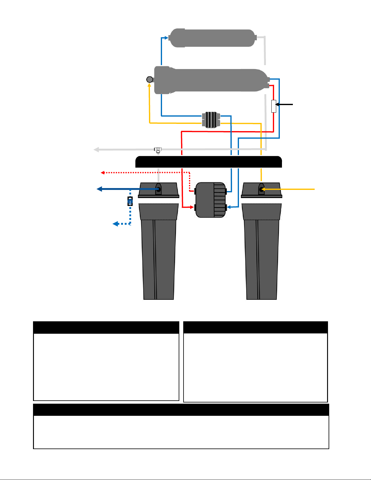
Reverse Osmosis System and Component Introducon
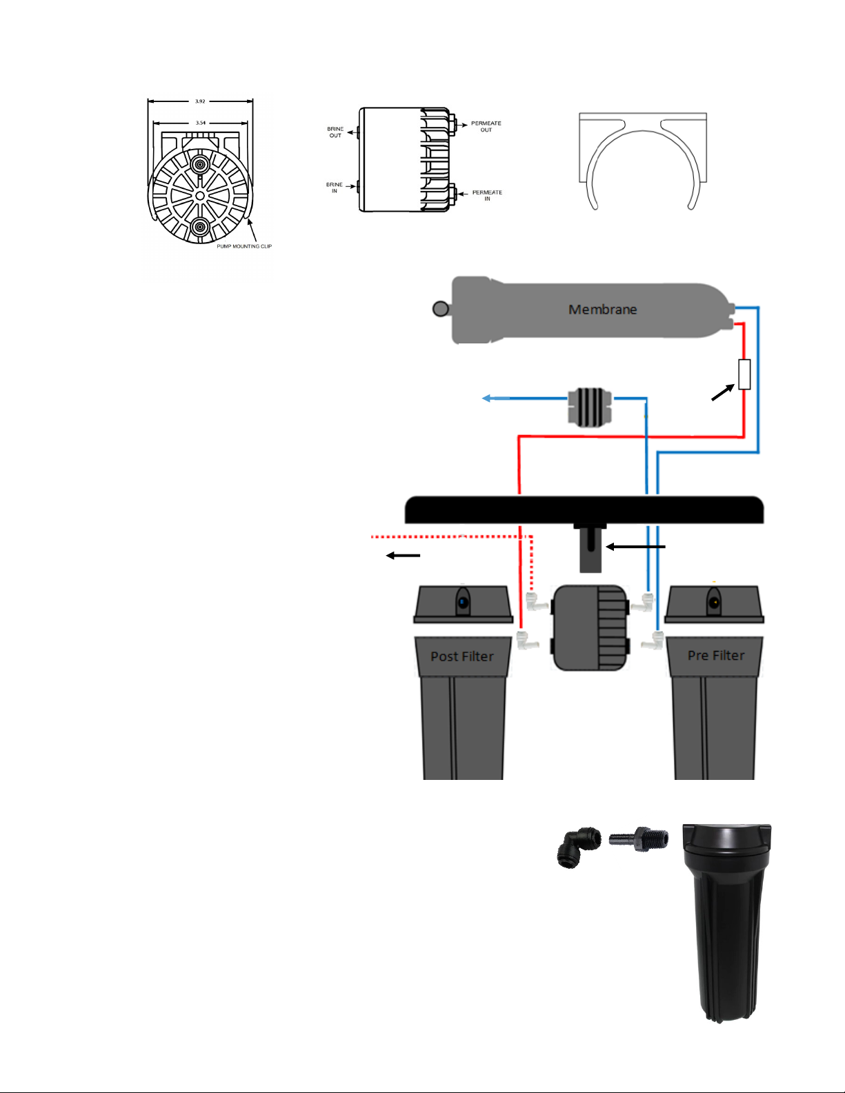
Permeate Pump
Remineralizaon Cartridge
Automac Shut-O Valve
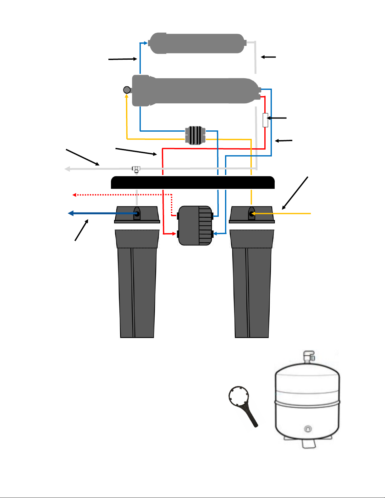
Your new Reverse Osmosis Drinking Water System (RO) uses a combinaon of ltraon and membrane technologies
and eciency components to provide the highest quality water possible. The following components combine to give
you high quality water in the most ecient way possible.
Pre and Post Filtraon
The rst stage is a 5 micron acvated carbon block, the pre-lter. Designed to reduce
chlorine that may be present to protect the membrane as well as eliminang taste
and /or odors. Another 5 micron acvated carbon block is the post lter in between
the storage tank and the faucet to give the RO water a fresh pass through carbon
before it goes into your glass.
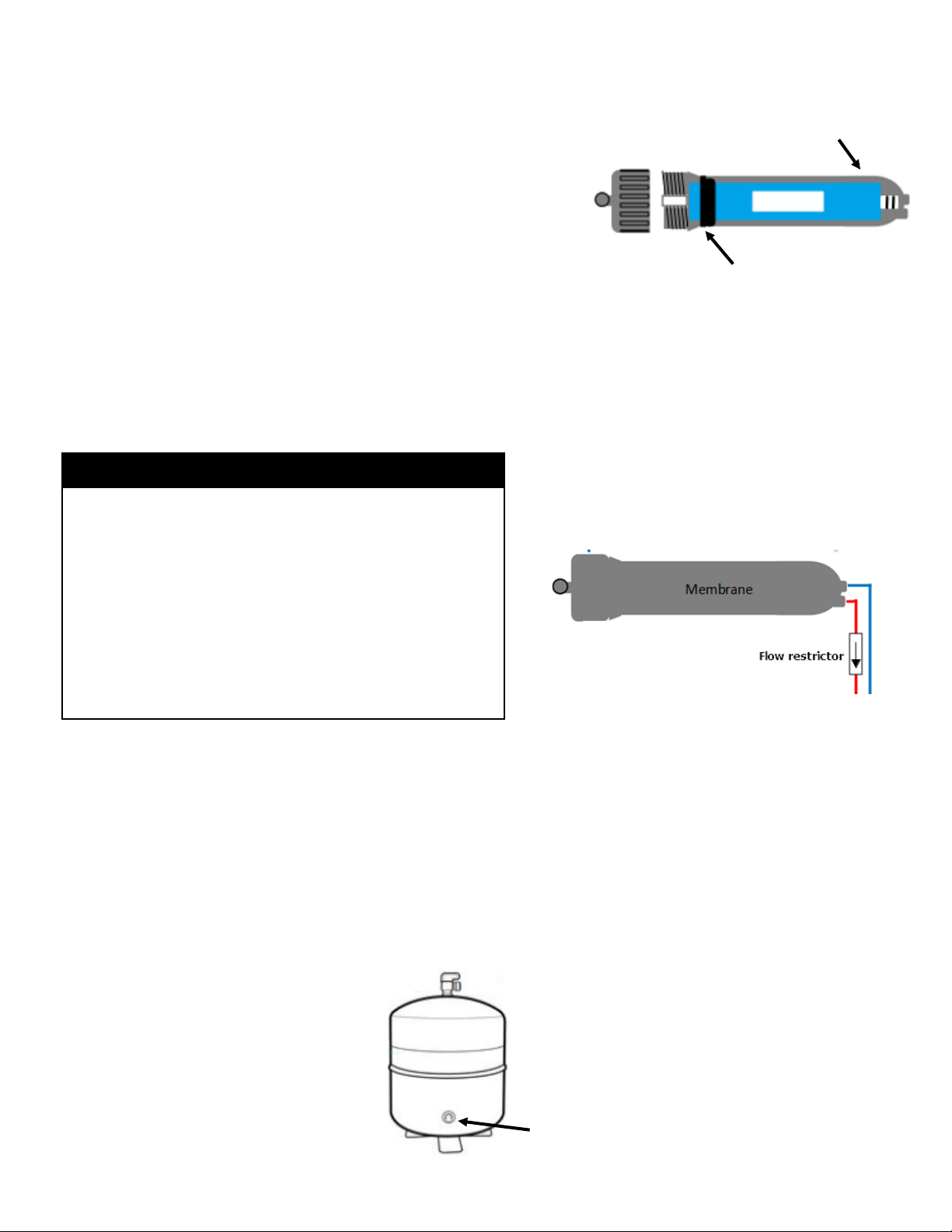
Reverse Osmosis Membrane
The RO Membrane is the heart of the ltraon system. It is designed to reduce the
dissolved mineral content of the water. Minerals picked up in the environment by the
water are measured as Total Dissolved Solids (TDS). In the Reverse Osmosis process,
dissolved minerals are separated from the incoming water (Feed Water) to produce
the product water (the Permeate). The excess minerals are rinsed to drain (the Reject
Water).
The membrane is a specially constructed, fully aromac polyamide lm and is
classied as a Thin Film Composite (TFC) The spiral wound construcon of the RO
Membrane provides maximum surface area for water producon and is less
suscepble to fouling by parculate maer, turbidity and colloidal materials.
This component provides the system eciency that most RO systems do not possess.
The Permeate Pump is a simple, yet revoluonary, device. Powered only by the
hydraulic energy of the reject water usually lost to the drain (i.e. no electricity
required), the Permeate Pump forces product water into the storage tank, reducing
membrane back pressure and maximizing available feed pressure. These pumps
dramacally improve the eciency of RO water producon, reducing wastewater by
up to 80%. It also enhances water producon and water quality from the membrane.
That means it will ll the tank faster and the water will be a higher quality!
The ASO Valve senses when the Holding Tank is full and closes the feed water supply. This
prevents excess reject water from going to drain when the unit is not producing water. This
device, used in conjuncon with the permeate pump makes this system one of the most
ecient available.
Water directly produced by the membrane travels through the ALKAline re-mineralizaon
cartridge. This increases water alkalinity through exposure to re-mineralizaon media boosng
the water’s pH and increases benecial mineral content.