Neolt Power Trim Plus 105 User manual


power trim plus
105 / 145 / 165 / 210 / 250
USER’S MANUAL
ENGLISH Cod. NLT.QN-A-C-MM-3-1S-GB NEOLT
USOGB-PWTP-1S.DOC 2003

CONTENTS
Power trim plus i
NEOLT
q
SECTOR:
POWER TRIM PLUS q
DATE:
12/01/2003
qVERSION: PWTP-01-01/2003 qAUTHOR: POLENI P.
Chapter 1General information ..................................................................................... 1
1.1 Data of the manual .................................................................................. 1-1
1.2 Users....................................................................................................... 1-1
1.3 Property of the information...................................................................... 1-1
1.4 Conventions used.................................................................................... 1-2
1.4.1 Conventional terms used .............................................................. 1-2
1.4.2 Conventional symbols used.......................................................... 1-2
1.5 Identification data of the manufacturer.................................................... 1-3
1.6 Identification data of the machine............................................................ 1-3
1.7 Warranty.................................................................................................. 1-4
1.8 Assistance .............................................................................................. 1-4
1.9 Use of the manual ................................................................................... 1-4
1.10 Description of the machine ................................................................... 1-5
1.10.1 Correct use of the machine......................................................... 1-5
1.10.2 Incorrect use of the machine....................................................... 1-5
1.10.3 Structure of the machine ............................................................ 1-6
Chapter 2 Safety information........................................................................................ 2
2.1 Safety criteria........................................................................................... 2-1
2.2 Qualifications of the personnel ............................................................... 2-2
2.3 Responsibility........................................................................................... 2-2
2.4 Danger zones and residual risks............................................................. 2-3
Chapter 3Characteristics of the machine................................................................... 3
3.1 Tecnical information................................................................................. 3-1
3.2 Machine performances............................................................................ 3-1
3.3 List of materials........................................................................................ 3-2
Chapter 4Installation ..................................................................................................... 4
4.1 Qualification of the operator..................................................................... 4-1
4.2 Transport.................................................................................................. 4-1
4.2.1 Transport conditions...................................................................... 4-1
4.2.2 Assessment of damages during transportation............................ 4-2
4.3 Assembling.............................................................................................. 4-3
4.4 Adjustments............................................................................................. 4-6
4.5 Storage .................................................................................................... 4-7
4.5.1 Features ........................................................................................ 4-7
4.6 Positioning ............................................................................................... 4-8
4.6.1 Characteristics of the area of installation ..................................... 4-8
4.6.2 Testing .......................................................................................... 4-8

CONTENTS
Power trim plus ii
NEOLT
Chapter 5Use ................................................................................................................. 5
5.1 Qualification of the operator..................................................................... 5-1
5.1.1 Working place................................................................................ 5-1
5.1.2 Insertion of the media to be cut..................................................... 5-1
5.1.3 Characteristics of the media to be cut........................................... 5-2
Chapter 6Maintenance.................................................................................................. 6
6.1 Routine maintenance............................................................................... 6-1
6.1.1 Qualification of the operator........................................................... 6-1
6.1.2 Procedure...................................................................................... 6-1
6.2 Extraordinary maintenance..................................................................... 6-1
Chapter 7Demolition...................................................................................................... 7
7.1 Qualification of the operator..................................................................... 7-1
7.2 Deactivation of the machine.................................................................... 7-1
7.2.1 Procedure...................................................................................... 7-1
Chapter 8List of attachments ..................................................................................... 8
Attachment AOptional roll holder ................................................................................ A
A.1 Assembly optional roll holder.................................................................. A-1
Attachment BOptional lamp for cutting area............................................................... B
B.1 Assembly of cutting area lamp............................................................... B-1
Attachment T1Technical Sheet ..................................................................... SCH-TEC
T1 Replacing rotating blade.............................................................. SCH-TEC-1

GENERAL INFORMATION
Power trim plus 1-1
NEOLT
Data of the manual 1.1
•Instruction manual.TRIMMER
•Code of the manual: NLT. QN-A-C-MM-3-1S-GB.
Users 1.2
Instruction manual.
•Transporter.
•Installer.
•User.
•Maintenance personnel.
•Demolition squad.
4For further details on the users of this manual, see 2.2 Qualifications of the personnel.
Property of the information 1.3
The information contained in this manual is reserved property. All rights are reserved.
This manual cannot be reproduced or copied, as a whole or in parts, without prior written
consent of NEOLT S.p.A. These documents are provided only for the use of the client
whom the manual has been supplied to with the machine, and can be used only for the
installation, use and maintenace of the machine the manual refers to.
NEOLT S.p.A. states that the information of this manual is congruent to the technical and
safety requirements of the machine the manual refers to. The manufacturer cannot be held
responsible for any direct or indirect damages to people, objects or animals due to the use of
these documents or of the machine in conditions other than those authorized..
NEOLT S.p.A. reserves the right to change or improve, without notice, these documents
and these machines, and also other machines marketed of the same model as the one this
manual refers to but with a different serial number. The information of this manual
particularly refers to the machine specified in 1.6 Identification data of the machine.
.

GENERAL INFORMATION
Power trim plus 1-2
NEOLT
Conventions 1.4
Conventional terms 1.4.1
Machine: indicates the machine specified in section 1.6 Identification data of the machine.
Frame: structure supporting the machine.
Qualified personnel: people, who thanks to their qualification, preparation and experience,
and thanks to the knowledge of the relevant rules, safety requirements and service norms,
are able to recognize and avoid any possible danger for the people, the material and the
machine.
The description of direction, sense and position (right side of the machine, left side of the
machine) refers to the operator standing in front of the machine.
Conventional symbols 1.4.2
Text in italic: indicates the title of a chapter, a section, a sub-section, a paragraph, a table, or
a figure of this manual or of another related publication.
1(example of a generic number): symbolic representation of a command or signaling
device.
A(example of generic letter): symbolic representation of a part of the machine.
4Notes contain important information, given outside the text to which they refer.
MThe danger symbols indicate those procedures which, if not respected, could cause physical
damages to the operator. The manufacturer cannot be held responsible for any damages to
people due to noncompliance with these norms.
&The warning symbols indicate those procedures which, if not respected, could damage the
machines or the devices connected to it. The manufacturer cannot be held responsible for
any damages to objects due to the noncompliance with these norms.
GENERAL INFORMATION
Power trim plus 1-3
NEOLT
Identification data of the manufacturer 1.5
neolt S.p.A.
Via G. Galilei, 8
24036 Ponte San Pietro (BG) -ITALY
Tel. 035/468811
Fax 035/468886
http://www.neolt.it
E-mail.: [email protected]
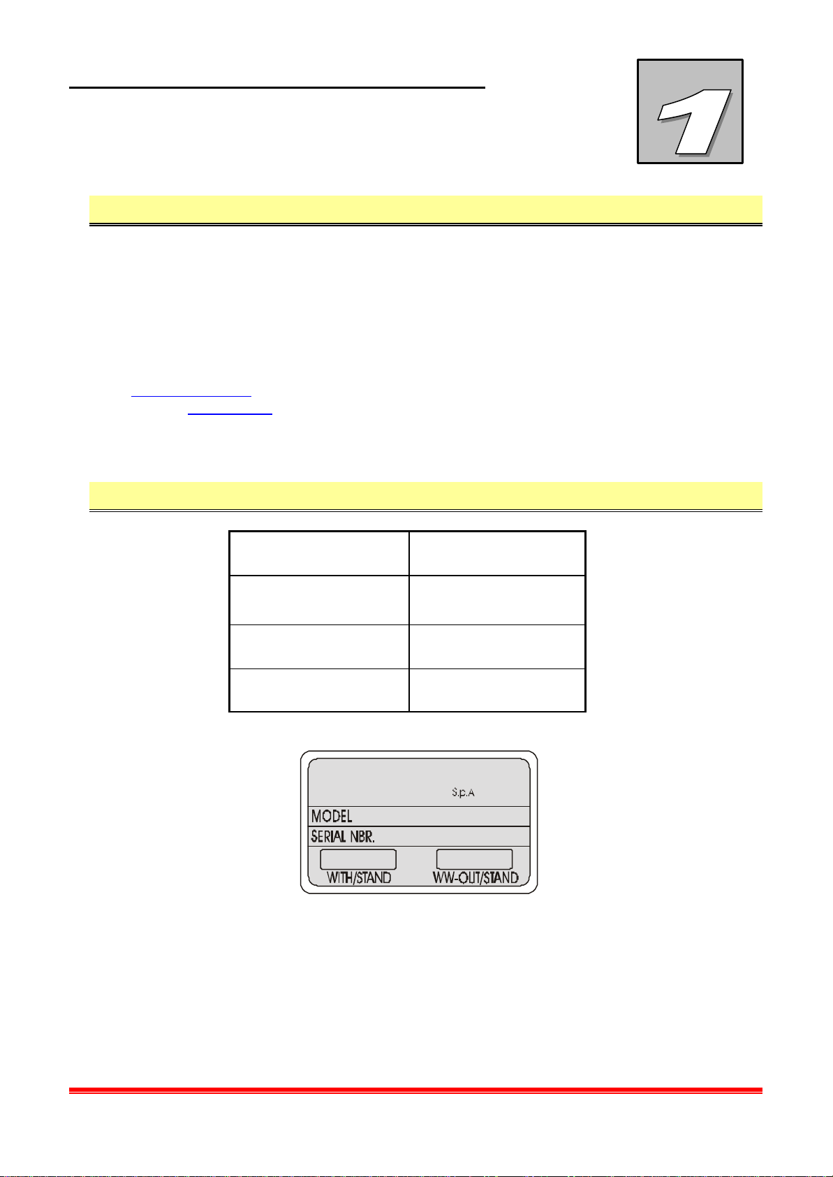
Identification data of the machine 1.6
Name TRIMMER
Model POWER TRIM
plus
Serial number
Year of construction
Neolt
ITALY

GENERAL INFORMATION
Power trim plus 1-4
NEOLT
Warranty 1.7
NEOLT S.p.A. warranty covers the machine for one year.
The parts subject to normal wear and tear are not included in the warranty. The warranty is
limited to the substitution or repair of the parts that should result damaged or defected.
The assessment of the defects and causes is carried out at NEOLT S.p.A. facilities.
The warranty is cancelled if the machine is used incorrectly, or in an improper or excessive
way, if any non-original spare parts are used and for noncompliance with the norms of this
manual.
In no case can the purchaser demand the resolution of the contract, claim for damages or
the extension of the warranty.
4NEOLT S.p.A. cannot be held responsible for any negative advertisement, or loss of
earnings, due to technical or mechanical malfunctioning of the product in use or in
display.
Service 1.8
NEOLT S.p.A. provides, on request, assistance for the installation and the maintenance
of the machine.
Use of this manual 1.9
Carefully read the chapters General information, Safety information, Characteristics of the
machine and Operator interface.
4Please consult the relative chapter for any transportation, installation, use, maintenance and
demolition operation.
This manual and the attached documentation must be kept for the entire technical life of the
machine in order to consult it quickly when necessary.
If the machine is sold as second-hand, this manual and the attached documentation must be
supplied along with the product.

GENERAL INFORMATION
Power trim plus 1-5
NEOLT
Description of the machine 1.10
Correct use of the machine 1.10.1
This machine can be used only to cut media having the allowed basic weight (max paper
thickness 2,2 mm).
As the machine consists of assemblies physically separated and autonomous, the proper
use of the machine can be identified also in the operation of a single part.
Foreseen modes of use
The installation and the extraordinary maintenance of the machine must be carried out by
qualified personnel only.
The machine has been designed to be used in a site having the following features:
•Protection against atmospheric agents.
•Proper illumination.
•Allowed range of temperature: from 18°C to 35°C.
•Allowed humidity range: from 30 % to 80 %.
Incorrect use of the machine 1.10.2
Any use other than that indicated in Section 1.10.1 Correct use of the machine is to be
considered incorrect, especially:
•Using the machine in ways which differ from those which it has been designed for,
represents an anomalous condition and could therefore damage the structure of the
machine.
•Using the machine without its protections and without the safety equipment.
•The non compliance with the procedures described in this manual, and specially those
concerning maintenance and repairing.
•The use of the machine in a site where fire and explosion risks are present, as the
machine is not provided with explosion proof devices.
•Its use in an explosive environment.
•Its use in an inflammable environment.

GENERAL INFORMATION
Power trim plus 1-6
NEOLT
Structure of the machine 1.10.3
The machine is composed of the
following parts:
AWork surface
BSupport
CPaper collector curtain
DContainment bracket
EBlade holder carriage
FSliding bar
Fig. 1.1 Lateral View
Fig. 1. 2 Detail
Fig. 1. 3
Prospect views
A
E
D
C
B
F

INFORMATION ON
SAFETY
Power trim plus 2-1
NEOLT
Safety criteria 2.1
During designing and manufacturing of this machine, all criteria and care in order to satisfy
the essential safety requirements foreseen by the relevant rules have been taken into
account.
The accurate evaluation of the risks performed by the manufacturer has allowed to eliminate
most of the risks concerning the usage conditions of the machine, both foreseen and
reasonably foreseeable.
The complete documentation including all the safety norms adopted is in the technical
booklet of the machine, which is deposited at the manufacturer's premises.
The manufacturer recommends strict compliance with the instructions, procedures and
recommendations of this manual and with the laws in force on the safety in the work place.
This also refers to the use of the protection devices foreseen, both those integrated in the
machine and personal.
4NEOLT S.p.A. cannot be held responsible for any damages to people, pets or objects due to
noncompliance with the safety rules and the recommendations contained in the
supplied documentation.

INFORMATION ON
SAFETY
Power trim plus 2-2
NEOLT
Personnel qualification 2.2
Stage of the technical life of the machine Qualification of the operator in charge
Transport Qualified transportation
Installation Qualified personnel
Use Qualified personnel
Routine maintenance Qualified personnel
Extraordinary maintenance Engineers authorized by NEOLT S.p.A.
Demolition Qualified personnel
Protections 2.3
4NEOLT S.p.A. cannot be held responsible for any damages to people, pets or objects due to
noncompliance with the safety rules and the recommendations contained in the
supplied documentation.
MTampering with the protections and the safety devices is dangerous for the people using the
machine and for those exposed to it.
4NEOLT S.p.A. cannot be held responsible for any damages to people, animals or objects
due to tampering with the protections.

INFORMATION ON
SAFETY
Power trim plus 2-3
NEOLT
Dangerous area and residual risks 2.4
All the areas around the machine in which people are at risk of injuries or health problems
are considered dangerous.
MPay close attention to hands when the
cutting operations.
During certain intervention procedures
on the machine, which are pointed out
each time in this manual, residual risks
for the operator may arise. Residual
risks can be avoided by carefully
complying with the procedures of this
manual and using the personal
protection devices indicated, such as:
•Maintenance and service operations
must be carried out only by the
engineers authorized by the
manufacturer.
•Paying attention to the danger
notices on the trimmer.
4NEOLT S.p.A. cannot be held responsible for any damages to people, animals or objects
due to noncompliance with the norms or avoidance in using the prescibed individual protection
devices (IPD).
Fig. 2. 1 Cutting zone

INFORMATION ON
SAFETY
Power trim plus 2-4
NEOLT

CHARACTERISTICS OF
THE MACHINE
Power trim plus 3-1
NEOLT
Technical specifications 3.1
MODEL 105 145 165 210 250
Max. cutting thickness (mm) 2,2 2,2 2,2 2,2 2,2
Usable cutting length (cm) 105 145 165 210 250
Length (cm) 128. 168 189 232 274
Width (cm) 39 39 39 39 39
Height (with holder) (cm) 95 95 95 95 95
Height of working table (cm) 87 87 87 87 87
Trim weight (kg) 20 26 28 30 34
Support weight (kg) 16 20 22 26 28
Accessori Roll holder –cutting area lamp
Performances 3.2
qMax. cutting thickness 2,2 mm

CHARACTERISTICS OF
THE MACHINE
Power trim plus 3-2
NEOLT
List of media 3.3
power
TRIM plus
Max. cutting thickness
Media
2,2 mm
Drawing paper X
Cardboard X
Cibachrome X
Slides X
Acrylic film X
Hot sealing film X
Carton X
Paper X
Photographic film X
Photographic paper X
Polypropylene film X
Fabric X
Jute X

INSTALLATION
Power trim plus 4-1
NEOLT
Qualification of the operator 4.1
Transport, installation and connection operations must be performed only by personnel
qualified in transportation and electrical operations.
Transport 4.2
Transport conditions 4.2.1
The trimmer is shipped with a packaging consisting of three cardboards 1 for components
protection, and of a carton box 2 containing all the components. Fig. 5.1 Transport
conditions.
The packaging size and its gross weight (trimmer plus packaging) are the following:
MODEL 105 145 165 210 250
Size (WxDxH -cm) 120x51x30 186x51x30 230x51x30 280x51x30 280x51x30
Weight (gross) -Kg 46 50 55 58 70
MPlease use suitable lifting devices and accessories, complying to the rules in force.
4To avoid shocks and turnover, apply the needed care. Protect the machine against external
atmospheric agents.

INSTALLATION
Power trim plus 4-2
NEOLT
Assessment of damages during transportation 4.2.2
Check the conditions of the machine by visually inspecting it, after having removed it from
the shipping box. Any defects on the visible parts of the machine indicate crashes during
transportation, which could also affect the ordinary operation of the machine.
In general, check screws and bolts for tightness.
Fig. 4.1
Transport conditions
2
1
INSTALLATION
Power trim plus 4-3
NEOLT
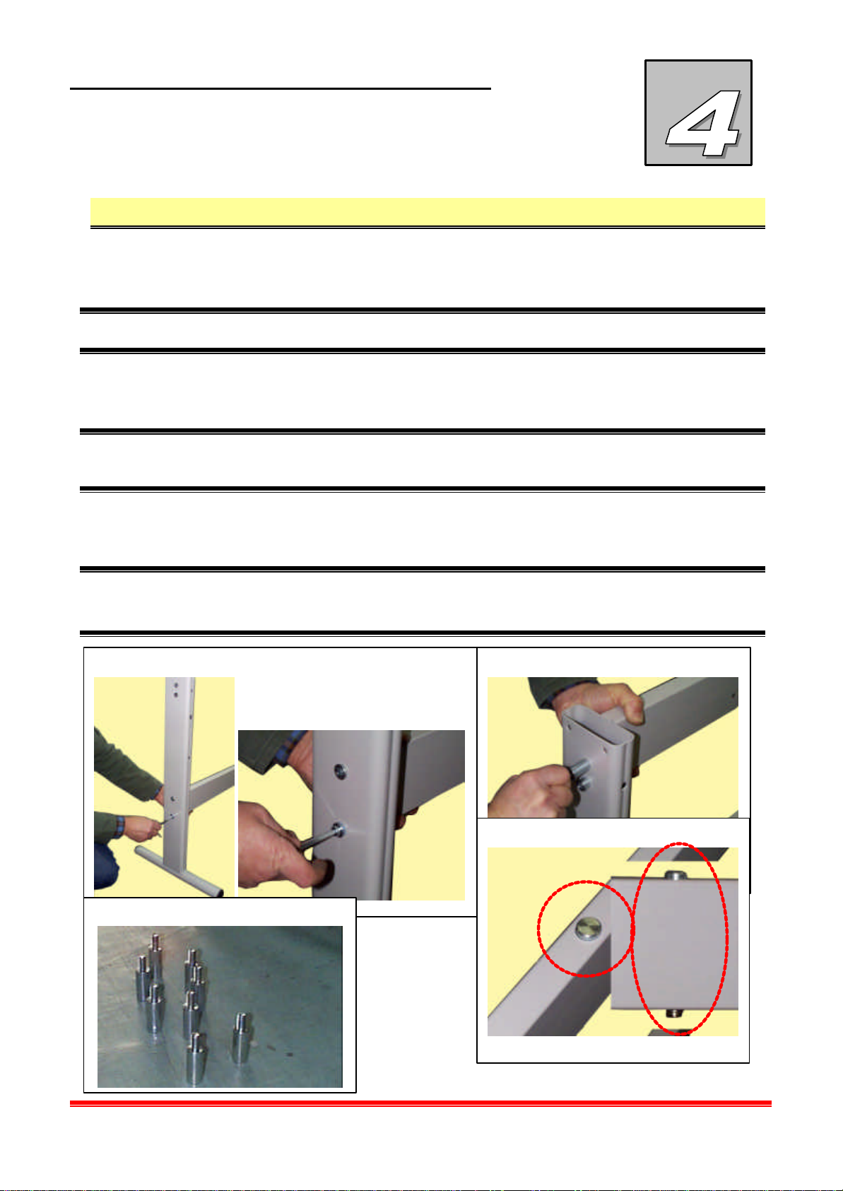
Assembly 4.3
•Open the packaging box 1 which contains all parts (Fig. 4.1 Transportation conditions).
•Remove the polyester protections 2(Fig. 4.1 Transportation conditions)
&This operation must be carried out by minimum two people.
•Screw on the lower cross-bar 3 first to one shoulder, then to the other with the supplied
screws and nuts 5 to assemble the support.
&Attention the shoulder has holes of different diameter, the side with the bigger holes must
face outwards.
•Screw on the upper cross bar 4to the shoulders following the procedure of the lower cross
bar, using the supplied screws and nuts 5.
&Attention when you position the upper cross bar, make sure the central pin is facing upward
6. The calibration set by Neolt is equal to 3 mm.
4
3
5
6

INSTALLATION
Power trim plus 4-4
NEOLT
•To assemble the paper collection basket, first slide in the basket holding bars in front
(bottom) 7and then back (top), and lock in the shoulder with two Benzing rings per bar 8, in
the appropriate seats.
•Slide the square bars in the appropriate
holes on the two sides of the basket.
•Screw on the two square rods to the
basket holding rods previously positioned
9.
•Avvitare i due supporti per il piano nella
Screw on the two supports for the table in
the front part on the upper cross bar using
the two supplied screws 10 .
7
9
8
frontback
frontback
10
This manual suits for next models
4
Table of contents


