Neomatica ADM33 User manual

«Neomatica» Wireless sensor-immobilizer ADM33, edition 1.1 dd 11.11.2019
1

«Neomatica» Wireless sensor-immobilizer ADM33, edition 1.1 dd 11.11.2019
2
Content
1. Application ......................................................................................................................................4
2. Technical features.........................................................................................................................5
3. Operation principle .......................................................................................................................6
4. Setting and installation order ....................................................................................................7
4.1. Installation order ....................................................................................................................7
4.1.1. Semiconductor switches mode ..................................................................................8
4.1.2. Electromechanical relay mode ...................................................................................9
4.2. Immobilizer operation with the tracker ADM333BLE .................................................10
4.2.1. Connection of immobilizer to the tracker ..............................................................10
4.2.2. Control of immobilizer statuses ...............................................................................11
4.2.3. Setting immobilizer ADM33........................................................................................11
4.2.3.1. Reading of the immobilizer current settings .....................................................13
5. Command description................................................................................................................15
6. Handling and transport regulations .......................................................................................17
7. Warranty obligations ..................................................................................................................17
8. Marking and packaging .............................................................................................................17
9. Disposal .........................................................................................................................................17
10. Scope of supply.........................................................................................................................18
11. Acceptance certificate .............................................................................................................18

«Neomatica» Wireless sensor-immobilizer ADM33, edition 1.1 dd 11.11.2019
3
This Operation manual relates to the wireless sensor-immobilizer ADM33 (hereinafter
referred as immobilizer). The manual also describes the immobilizer operation with the tracker
ADM 333 BLE manufactured by Neomatica LLC.
The Operation manual is designed for professionals who have familiarized themselves
with the rules of repair and installation works execution on vehicles and who have special
professional knowledge in electronic and electric equipment used on various transport means
The immobilizer proper work is guaranteed if it is installed and set by qualified
professionals. To use the immobilizer properly it is necessary to familiarize with the monitoring
system work principles in general and to understand the function of all its components
«Neomatica» Wireless sensor-immobilizer ADM33, edition 1.1 dd 11.11.2019
4
1. Application
Immobilizer is used for being installed on moving and stationary objects to control
electrical circuit.
Immobilizer can operate as a part of monitoring system with the tracker ADM333 BLE.
Immobilizer can be used as an electromechanical relay with switching group of contact
elements or as a two-channel output with overcurrent protection.
Can be installed on vehicles to block electrical circuit of the ignition system or of the
fuel supply in order to block the engine work or engine start-up. Can be installed on stationary
objects as a switcher with wireless control.
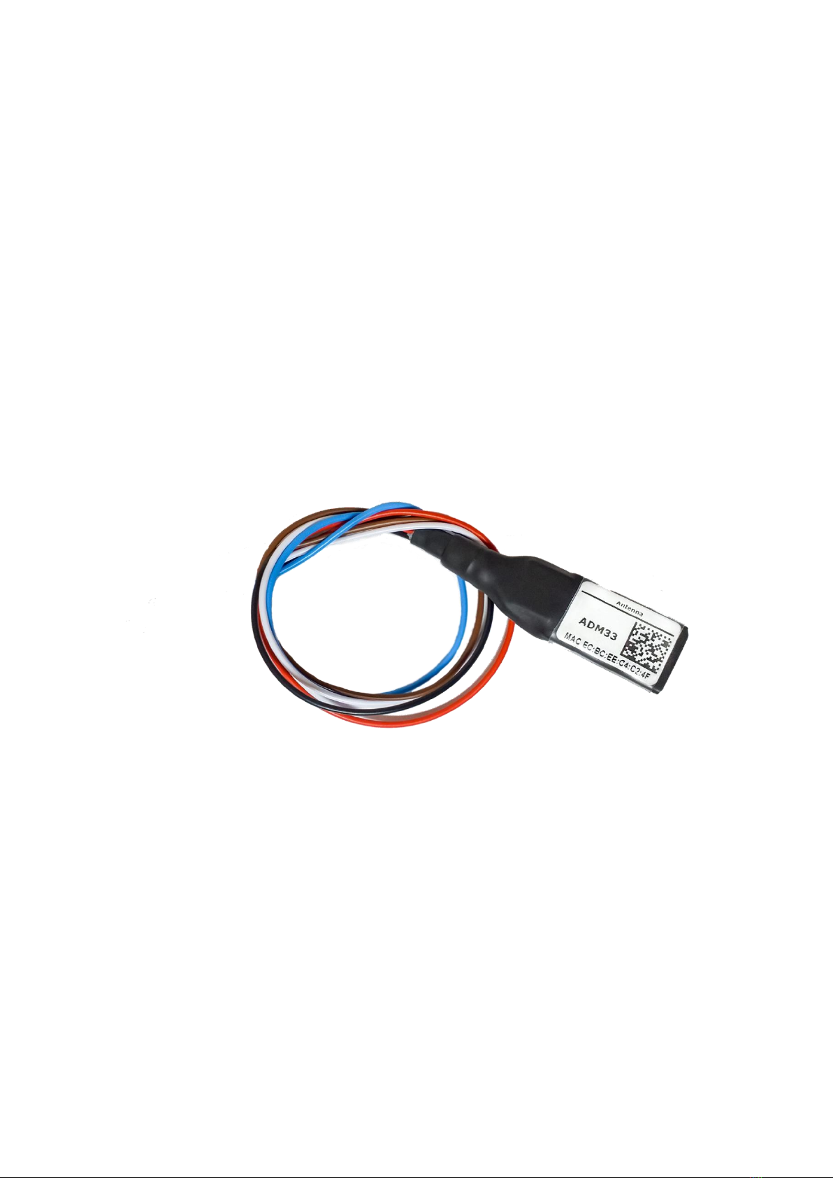
Fig. 1. ADM33 general view

«Neomatica» Wireless sensor-immobilizer ADM33, edition 1.1 dd 11.11.2019
5
2. Technical features
•Operation temperature range: from - 40°С up to + 85°С;
•Data transmission: Bluetooth Low Energy 4.1;
•Radio interface frequencies range: 2400...2483,5 MHz;
•Transmitter power: +4 dBm;
•Receiver sensitivity: -96 dBm;
•Coverage: up to 50 m at direct line of sight;
•Maximum supply voltage while using electromechanical relay: 15V;
•Rated current in contact elements of electromechanical relay: 9 A;
•Maximum voltage of the contact elements of electromechanical relay: 16 V;
•Maximum supply voltage when using semiconductor switches: 40 V;
•Maximum commuted current of semiconductor switches: 0.9 A;
•Maximum voltage between GND and NO outlets (Output 1): 40 V;
•Maximum voltage between GND and NС outlets (Output 2): 40 V;
•Maximum voltage between GND and COM outlets: 40 V;
•Current at which protection of semiconductor switches is activated, at t=25°С: 1.3 А;
•Consumption current (at supply voltage of 12 V): 2мА - 6мА when the semiconductor
switches and electromechanical repay are switched off;
•Consumption current (at supply voltage of 12 В): 8мА when the semiconductor
switches are switched on, without load;
•Consumption current (at supply voltage of 12 V): 55мА when electromechanical relay
is switched on;
•IP class: IP65;
•Body material: polyolefin;
•Dimensions, mm: at most 17 x 21 x 80 (380 with cables);
•Weight: at most 34 g

«Neomatica» Wireless sensor-immobilizer ADM33, edition 1.1 dd 11.11.2019
6
3. Operation principle
Immobilizer ADM33 consists of microcontroller, accelerometer, two semiconductor
switches with current protection, electromechanical relay, Bluetooth LE radio interface.
Microcontroller processes received commands via Bluetooth LE radio channel and
controls semiconductor switches and electromechanical relay basing on these commands,
signals from accelerometer and chosen operation algorithm.
When supply voltage is 15V, semiconductor switches and electromagnetic relay can
be used.
When supply voltage is more than 15 V, only semiconductor switches can be used and
the use of electromechanical relay is prohibited.
The outlets of semiconductor switches and electromechanical relay are combined, that
is why their simultaneous operation is impossible.
The outlets functions are different in different modes.
«СOM», «NC», «NO» outlets have got galvanic connection with immobilizer power
supply circuit. (Outlets «+» and «GND»). The voltage between any of «СOM», «NC», «NO»
outlets and any of + and GND outlets must not exceed +40 V, otherwise immobilizer can be
damaged.
It is necessary to use additional relay or other suitable unit to provide galvanic isolation
between external power supply circuit and immobilizer power supply circuit. When using
external relay set semiconductor switches mode to reduce power consumption in the “on”
position.

«Neomatica» Wireless sensor-immobilizer ADM33, edition 1.1 dd 11.11.2019
7
4. Setting and installation order
1. Select immobilizer working mode;
2. Select way of connection;
3. Connect immobilizer to the tracker ADM333 BLE;
4. Set immobilizer;
5. Connect to the power supply and secure immobilizer body.
4.1. Installation order
•Deenergize power circuit where installation is planned. When installing on a vehicle
switch off “minus” clamp of the accumulator.
•Place immobilizer in a hard-to-reach place to avoid interaction with moving parts of the
vehicle.
To prevent bad quality of Bluetooth LE radio signal it is not recommended to put
immobilizer into metallic housings, truck body and other massive metal structures. It is
possible to put the immobilizer under plastic panels, housings and other plastic
structures. There is “Antenna” marking on the immobilizer sticker (label), the position
of such marking coincides with the position of the antenna of Bluetooth LE radio
interface. When installing the immobilizer into a cord assembly the antenna should be
placed upwards. Do not install the immobilizer in places where the temperature is equal
to or above the motor operation temperature (pipes of motor cooling system, exhaust
system, etc.).
•Fix the immobilizer with the help of clamps or cable binders.
•Connect the immobilizer to power supply (Red cable (+) and Black cable (GND)).
Connect GND cable to main power source or to the truck body. When using
semiconductor switches connect “GND” outlet to the power source that is able to
provide the current used by load connected to “Output 1” and “Output 2”. Maximum
current in the Black cable (GND) must not exceed 2.6 A.
To connect Red cable (+) use the main vehicle power source with steady voltage of 10
V up to 40 V.

«Neomatica» Wireless sensor-immobilizer ADM33, edition 1.1 dd 11.11.2019
8
If there is a direct connection to the accumulator clamp then use a fuse to protect the
cable.
•Connect cables COM, NO, NC to the electrical circuit that should be blocked. When
installing such circuits make quality connections using the methods applicable in a
particular case, as well as take into account the length and the cable wire section,
because the current in such circuits may be rather powerful.
4.1.1. Semiconductor switches mode
In such a mode the switching of the minus of power supply (output "GND") with the
outputs "Output 1" and "Output 2" is carried out by means of semiconductor switches. In such
a mode the immobilizer switches only the minus of power supply load. The plus of the power
supply load should be connected from any appropriate section of power supply network. The
function of the outlets in the semiconductor switches mode is given in figure 2.
To switch the power supply of a powerful load, which consumption current exceeds the
maximum current of the semiconductor switch, use additional relay. In case of necessity to
switch the plus of the power source also use additional relay. The scheme of the connection
of additional relay is given in figure 3.
Do not connect outputs 1 and 2 in parallel to increase the maximum load current.
Fig.2 ADM 33. Scheme of contact elements when using semiconductor switches.
1. Red cable — + (plus of the power source);
2. Black cable — GND (minus of the power source);
3. Blue cable — is not used (should be isolated);
4. White cable — Output 1;
5. Brown cable —Output 2.

«Neomatica» Wireless sensor-immobilizer ADM33, edition 1.1 dd 11.11.2019
9
Fig. 3. ADM33. Scheme of external blocking relay connection.
4.1.2. Electromechanical relay mode
In such a mode the outlets «СOM», «NC», «NO» are considered to be the outlets of
electromechanical relay with switching group of contact elements.
Common outlet “COM” is switched to the outlet “NC” or to the outlet “NO”. When the
voltage is not supplied to the electromechanical relay coil as well as to the immobilizer then
outlet “NC” is closed to the outlet “COM”.
Functions of the outlets in electromechanical relay mode are indicated in figure 4.
Fig. 4. ADM33. Scheme of contact elements when using electromechanical relay
1. Red cable — + (plus of the power source);
2. Black cable — GND (minus of the power source);
3. Blue cable — COM (common contact element);
4. White cable — NO (normally-open contact element);
5. Brown cable — NC (normally-closed contact element).
«Neomatica» Wireless sensor-immobilizer ADM33, edition 1.1 dd 11.11.2019
10
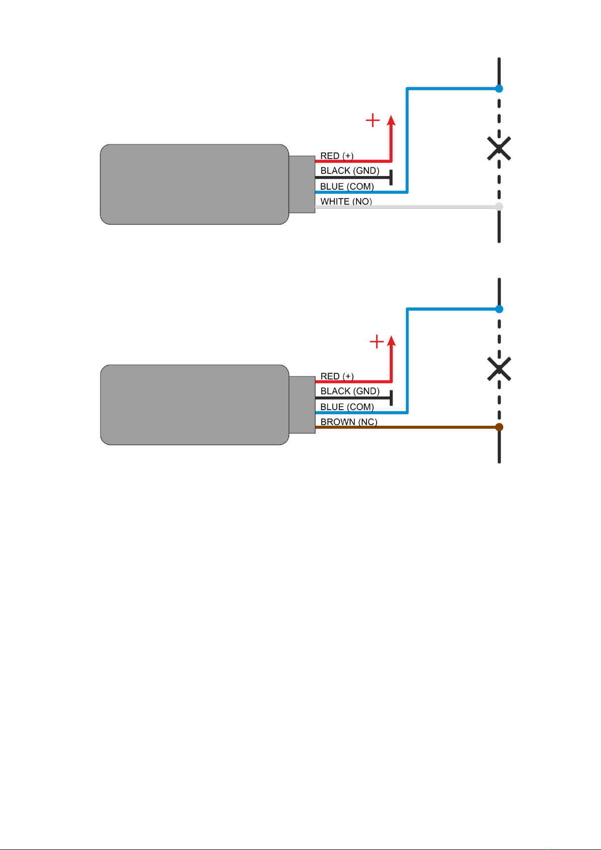
Fig 5. ADM33. Use of normally open contact elements for lockup
Fig. 6. ADM33. Use of normally closed contact elements for lockup
4.2. Immobilizer operation with the tracker ADM333BLE
The immobilizer is managed by the tracker. The setting of interaction between the
immobilizer and the tracker ADM333 BLE (hereinafter referred as tracker) is performed by
sending commands to the tracker via Bluetooth, GPRS and SMS.
4.2.1. Connection of immobilizer to the tracker
BLEOUTADDR command allows adding MAC-address of the immobilizer as well as
looking through the list of added addresses. Immobilizer MAC-address is given on the sticker
of the immobilizer body. When entering the address, no need to put a colon.
BLEOUTADDR X — add the address X;
BLEOUTADDR X,0 —clear the box X;
BLEOUTADDR — display the list of addresses added in the tracker.

«Neomatica» Wireless sensor-immobilizer ADM33, edition 1.1 dd 11.11.2019
11
4.2.2. Control of immobilizer statuses
BLEOUTPUT command is used to switch the status of electromechanical relay or of
semiconductor switches. The data entered with the help of this command are recorded in
non-volatile memory and saved there when the power is turned off or the tracker is rebooted.
BLEOUTPUT X – set immobilizer status X
•Status 0 (X=0)
Electromechanical relay: COM+NC outlets are closed, COM+NO outlets are open.
Semiconductor switches: off
•Status 1 (X=1)
Electromechanical relay: COM+NC outlets are open, COM+NO outlets are closed.
Semiconductor switches: on
Example:
BLEOUTPUT 1 – set immobilizer status 1;
4.2.3. Setting immobilizer ADM33
Use BLEOUTCFG command to set the immobilizer. ADM33 stops Bluetooth
environment scanning process and starts broadcasting Advertising messages.
To configure settings and select immobilizer modes use a smartphone with operation
system Android .5.0 or earlier as well as nRF Connect application. To connect the immobilizer
to the smartphone via Bluetooth do the following:
1) Activate Bluetooth-adapter of the smartphone;
2) Activate geolocation;
3) Start up nRF Connect program (is available for downloading in Play Store
https://play.google.com/store/apps/details?id=no.nordicsemi.android.mcp);
4) Allow nRF Connect application to use Bluetooth and geo position;
5) Supply power to the immobilizer;
6) Send BLEOUTCFG command to the immobilizer from the tracker;
7) nRF Connect will display the immobilizer in the list of detected devices;
8) Click on the right-side button in nRF Connect;

«Neomatica» Wireless sensor-immobilizer ADM33, edition 1.1 dd 11.11.2019
12
9) In a new tab a window will appear with the demand to enter a password. Enter a
password for authorization. By default is 123456;
10) After connection, on the first tab there will be three sections: “Generic Access”,
“Generic Attribute”, “Nordic UART Service”. Press “Nordic UART Service”. There will
appear the following menu:
11) Field “RX Characteristic” will be used for settings and commands sending. Field “TX
Characteristic” will be used to display responses. Next to the field “TX Characteristic”
there are three arrows pointing down. Click on these arrows, afterwards they will be
crossed out by a cross. Now the immobilizer is ready to receive your commands.
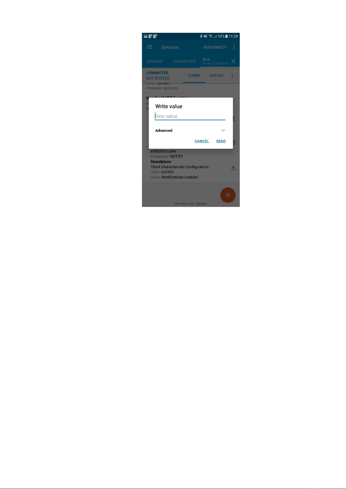
12) To send commands click on the arrow pointing up, next to the field “RX Characteristic”.
There will appear a window for entering the following commands:
«Neomatica» Wireless sensor-immobilizer ADM33, edition 1.1 dd 11.11.2019
13
13) Save the changes after settings. Otherwise the settings will return to initial values in
case of rebooting (power turn off). To save the settings use wf command – settings
record;
14) Having recorded the settings, disconnect from the immobilizer. To do this click on
“Disconnect” in the upper-right corner.
General rules for writing and sending commands:
⎯ Only Latin alphabet characters are used in commands;
⎯ Lower case characters;
⎯Commands are separated by SPACE;
⎯ Parameters are set using Latin letters and Arabic numerals
Having received a command, the immobilizer performs it and sends the response in a
message. If command parameters are beyond permissible limits the immobilizer changes
these parameters to the nearest permissible values. The immobilizer will not response the
command if it is impossible to change the parameters or the parameters are not enough.
4.2.3.1. Reading of the immobilizer current settings
•To read current parameters use command rs.
The command sends response in the following form:

«Neomatica» Wireless sensor-immobilizer ADM33, edition 1.1 dd 11.11.2019
14
rs: [parameter ID]=[parameter value];[parameter ID]=[parameter value] and etc.
List of parameters ID :
12 — protection against messages substitution from controlling tracker (sf command
is used)
13 — mode of immobilizer operation (cr command is used)
14 — initial status of immobilizer (br command is used)
15 — emergency status of immobilizer (ar command is used)
16 — actions, action to be done when connection with the tracker is lost (ts command
is used)
17 — frequency of control messages receipt from the tracker, in the status of
immobilizer setting (ad command is used)
18 — time of signal waiting from the tracker after which the connection is considered
to be lost. (ta command is used)
19 — inversion of the status of electromechanical relay and semiconductor switches.
(ri command is used)
•To read service information use rb command.
The command sends response in the following form:
rb: [parameter ID ]=[parameter value];[parameter ID ]=[parameter value] and etc.
List of parameters ID:
1 — main firmware version.
2 — firmware version.
3 — type of device.
4- configuration version

«Neomatica» Wireless sensor-immobilizer ADM33, edition 1.1 dd 11.11.2019
15
5. Command description
Command
Answer
Parameters
Description
1
be
be
Command without parameters
Switch to firmware update mode
2
ds
ds
Command without parameters
Reset to the factory settings
3
rs
rs
Command without parameters
Description of response
4
rb
rb
Command without parameters
Description of response
5
wf
wf
Command without parameters
Save settings
6
cp X
cp
X – password. Consists only of Arabic numerals
Password change
7
сr X
cr
X – operation mode
0 – electromechanical relay;
1 – semiconductor switch (only output 1);
2 – semiconductor switch (only output 2);
3 – semiconductor switch (outputs 1 and 2).
Select immobilizer operation mode
8
br Х
br
Х – immobilizer status
0 – COM+NC (by default);
1 – COM+NO.
Select initial immobilizer status after
power switch on
9
ar Х
ar
Х – immobilizer status
0 – COM+NC;
1 – COM+NO (by default).
Select emergency status of immobilizer
10
ts
ts
Х – types of actions:
0 – do nothing;
Action to be performed at the absence of
connection with the tracker.

«Neomatica» Wireless sensor-immobilizer ADM33, edition 1.1 dd 11.11.2019
16
1 – immediately switch to emergency status;
2 – switch to emergency status in case of no
movement;
3 – switch to emergency status in case of
movement.
11
ta Х
ta
Х – time in seconds.
Time of command waiting from the
tracker after which the connection is
considered to be lost
12
ad X
ad
Х – time in seconds.
Waiting time when immobilizer is waiting
to be connected to the tracker
13
ri Х
ri
X=0 – inversion is switched off;
X=1 – inversion of electromechanical relay status;
X=2 – inversion of semiconductor switch 1 status;
X=4 – inversion of semiconductor switch 2 status;
X=6 – inversion of semiconductor switches 1 and 2
status
Inversion of immobilizer status
14
sf Х
sf
Х – protection status.
0 - off;
1 -on.
Activation of protection against
messages substitute from the tracker

«Neomatica» Wireless sensor-immobilizer ADM33, edition 1.1 dd 11.11.2019
17
6. Handling and transport regulations
Immobilizers should be stored in a warehouse at a temperature of +5 °C up to +40 °С
and relative humidity at most 85 %. After immobilizers transportation in sub-zero temperatures
they should be stored at room temperature within 24 hours.
7. Warranty obligations
The manufacturer guarantees the immobilizer proper function within 12 months from the
day of its sale if consumer meets all the requirements and follows all the rules of
transportation, storage, installation and handling. The warranty does not cover:
-immobilizer with mechanical damages and defects (cracks and chips, dents, signs of
impacts, etc.) caused by consumer as a result of handling, storage and transportation rules
violation. When there are signs of oxidation or other proofs of liquid penetration in the device
housing;
-immobilizer with signs of electrical and/or other damages caused as a result of improper
use. The device software is licensed, terms related to the manufacturer's limited liability in the
framework of the License Agreement are provided at the web site
https://neomatica.com/upload/docs/license.pdf
8. Marking and packaging
Marking is placed on the housing of wireless immobilizer ADM33. The immobilizer is
packed in an individual package or in a multi package
9. Disposal
Device recycling is performed according to national and local norms and requirements.

«Neomatica» Wireless sensor-immobilizer ADM33, edition 1.1 dd 11.11.2019
18
10. Scope of supply
Device name
Quantity
Comments
Wireless sensor-immobilizer ADM33
Passport
11. Acceptance certificate
Wireless sensors-immobilizers ADM33, operation manual No. ШАИФ.464512.004 in
quantity of _____ pcs are considered to be ready for operation.
Date of manufacture:
Manufacturer: Neomatica LLC
24а Malkova, office 7, Perm 614087, Russia
Tel: +7 (342) 2-111-500 (ext. 42), +7 909 100 90 90
E-mail: [email protected]
Web-site: http://neomatica.com
Table of contents
Popular Car Alarm manuals by other brands


Suzuki
Suzuki Alarm System 2001 Ignis Operator's manual

Sparkrite
Sparkrite SR85 instruction manual

Directed Electronics
Directed Electronics 381 Series owner's guide

Volvo
Volvo P-3-39-165 installation instructions

ATS
ATS NASA 2001 Operation manual

Directed Electronics
Directed Electronics 554R owner's guide