NeoRe 8TG HP User manual
User manual
NeoRé TG
Heat pump air-water
NeoRé TG
NeoRé 8TG
NeoRé TG
NeoRé TG
NeoRé 8TG HP
NeoRé TG HP
NeoRé TG HP
NeoRé 6TG HP
All rights and changes reserved. Last update .8. -..
Quick start
The quick start guide can only be used if the heat pump installation has been completed, properly started and tested
by the installation company.
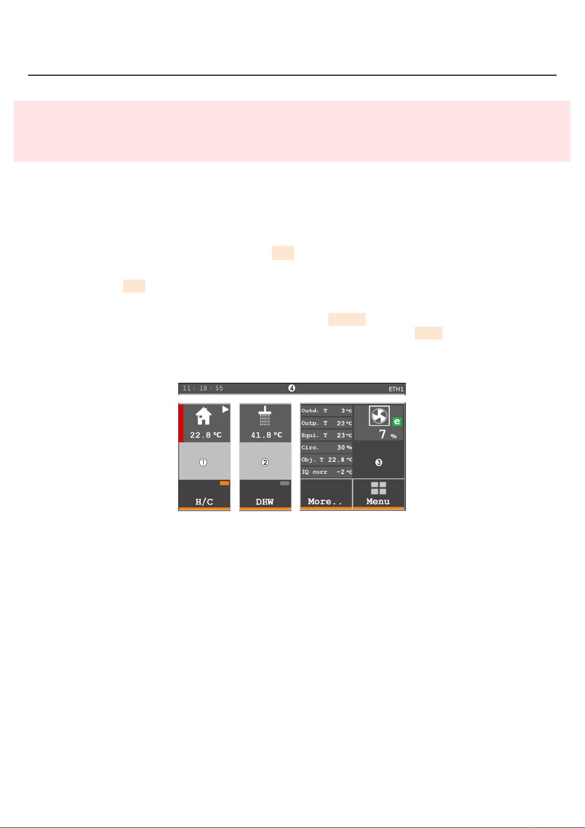
Division and description of the basic control screen
.Object section - Displays heating / cooling mode, building temperature, circulating pump operation and building states.
To turn the heating and cooling on and off, use the H/C button.
.DHW section - Displays the DHW temperature, circulating pump operation and heating states. To turn on the DHW
heating, use the DHW button.
.Overview section - Displays values and parameters of selected temperatures, operating states and the outdoor unit
power. You can also switch to an extended overview using the More.. button, which contains more values, a fault
history, measurement of supplied heat and more. To return to the main menu, press Menu .
.Information bar section - This part displays the time and state of the device. On the right side, you can see if the heat
pump is connected to an Ethernet network (ETH) and the Neota Route remote access service (CLOUD)
Figure : Basic division of sections (H/C on, DHW off)
Basic operation of the controller
To operate the heat pump, use the graphical user interface on the touch panel. The main menu will be displayed immedi-
ately after switching on the device or after pressing the Menu button. A complete description of the functions and operation
is given in Chapter Description of the user interface (page ).
Overview is used for basic control – activation of heating, DHW heating, overview of temperatures and energies, list of
states and errors.
Object is used for advanced setting of the requirements for building heating or cooling.
DHW is used for advanced setting of the requirements for DHW heating, its circulation and disinfection.
Graphs displays the course of important temperatures
Settings is used for general setting of the device behaviour and remote access.
More is used to set additional systems such as a secondary source or pool circuit.
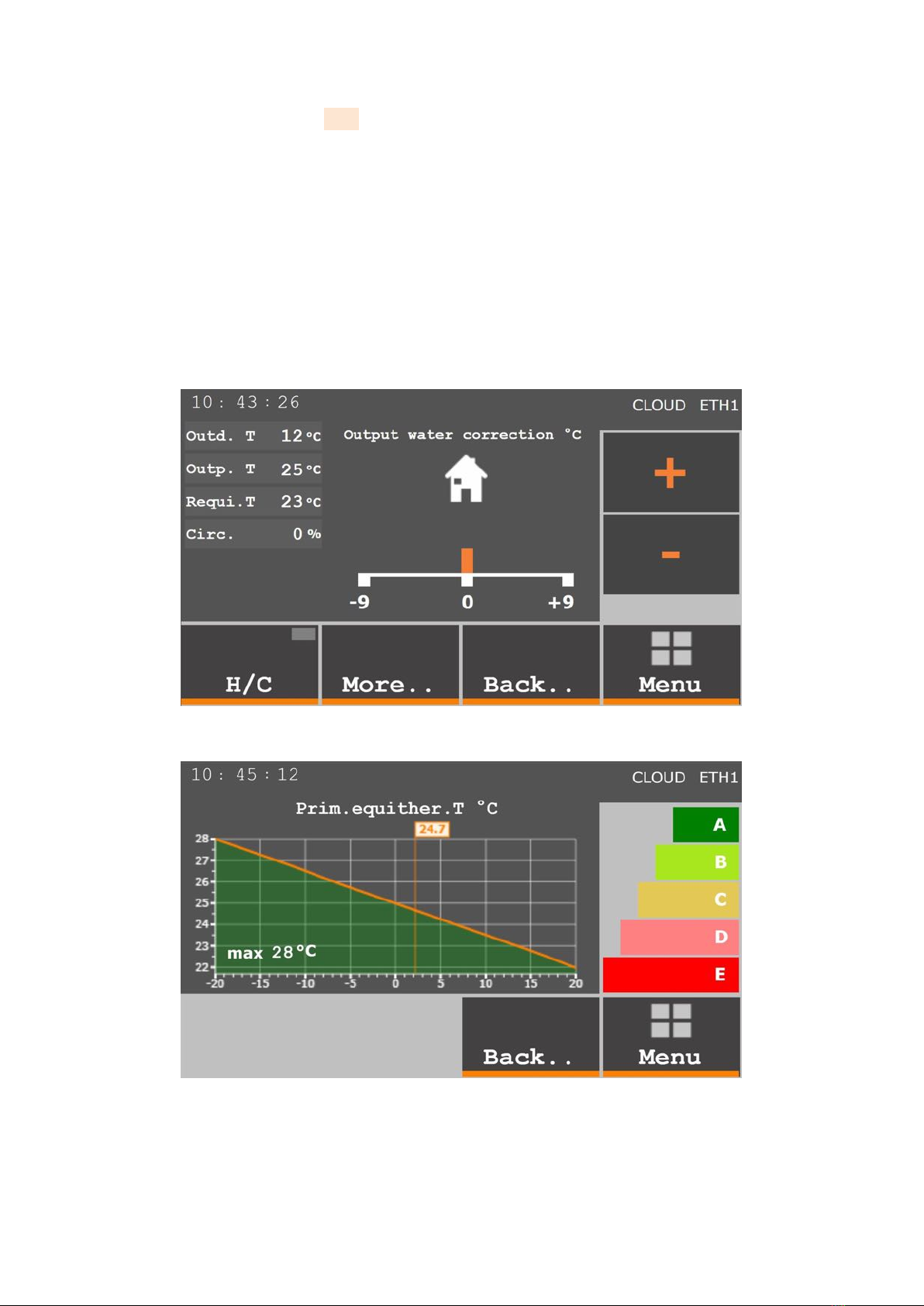
Winter operation
On the Overview screen, switch on the H/C icon (the rectangle on the button is orange).
You can set the equithermal curve in a simplied mode after pressing the house icon in the rst column. It is the SIMPLE
NEO function.
H/C is used to switch heating/cooling on or off like on the previous screen.
More.. is used for initial selection of the equithermal curve according to the energy class of the building. Just press the
coloured label in the right column and the weather compensation curve will automatically readjust (Fig. )
Back.. is used to return to the Overview
Menu is used to return to the default screen
Plus Minus is used to increase/decrease the desired temperature of heating/cooling water by a maximum of °C from the
default temperature
Figure : Basic screen SIMPLE NEO for equithermal curve correction
Figure : Initial selection of the equithermal curve according to the energy class of the building

For experts: More accurate but complex setting of the equithermal curve according to Table on page can be made in
the Object settings. Then use automatic equithermal curve correction to adjust the heating water temperature according to
your needs.
Equithermal setting
Heating water temperature for:
Outdoor temperature
Floor or ceiling heating Radiators
19°C22°C25°C
6°C28°C40°C
7°C33°C45°C
20°C38°C50°C
Table : Equithermal curve setting
�If it is too hot or too cold in the heated area, adjust the equithermal curve using the Automatic correction func-
tion (Object Primary weather comp. curve). For example, if the room temperature is 2°C higher than desired,
enter a value of equithermal curve automatic correction of 3°C. If, on the other hand, the room temperature is
1°C lower than desired, enter a correction of 2°C. The minimum correction value is ±3°C for one entry. Remember
that the change requires some time to take effect. In the case of oor heating, this time during which the room
temperature changes is approximately –6 hours. In the case of radiators, this time is shorter.
Summer operation
To switch to the cooling mode in summer, use the Mode – heating/cooling selector on the Object section screen (Fig.
. page ). In the cooling mode, the selector is blue and, on the basic Overview screen, there is a blue stripe next to the
house icon.
DHW heating
On the overview screen (section Overview), set the DHW icon to ON. In the DHW settings, set the desired DHW temperature
and delay of electric heating according to Table on page . DHW heating operates independently in both modes, heating
as well as cooling.
Setting the delay of DHW electric heating
Vessel size Delay time
l min
l6min
l min
Table : Setting the delay of DHW electric heating

Contents
Safety instructions
.Safetywarning......................................................
.Safetyprecautions....................................................
.Legalconditions..................................................... 8
.Storageandtransportconditions ...........................................
Product specication
.Productdesignation...................................................
.Connectiontothemains ................................................
.Packagecontents ....................................................
.Indoorunitdescription .................................................
.Outdoorunitdescription ................................................
.6 Tableoftechnicalparameters .............................................
Principle of operation and correct use
.Principleofheatpumpoperation............................................
.Hotwaterheatingsystems...............................................
..Low-temperatureheatingsystem .......................................
..Medium-temperatureheatingsystem.....................................
.Coolingsystem......................................................
.Correctprinciplesofusingaheatpump........................................
Description of the user interface
.Defaultscreen ......................................................
.Overview ......................................................... 6
..Meaning of graphic symbols and text abbreviations . . . . . . . . . . . . . . . . . . . . . . . . . . . . .
..Simplied setting of the weather compensation curve – SIMPLE NEO . . . . . . . . . . . . . . . . . .
.Object...........................................................
.DHW............................................................
.Graphs .......................................................... 8
.6 Settings.......................................................... 8
.More............................................................
.8 Webserveroperation ..................................................
.NeotaRoute(cloud)...................................................
. Localnetworkconnection................................................
. SimplyNeomobileapplication............................................. 6
Commissioning
.Commissioningoftheheatingsystem ........................................
.Activation ........................................................
6 Shutdown 8
6.Short-termshutdown .................................................. 8
6.Long-termshutdown .................................................. 8
Faults and status messages
.Errorcodestructure...................................................
.Overviewoffaultsandstatusmessages .......................................
.Faultsandtroubleshooting ...............................................
.Statusmessages ....................................................
.Protectivefunctions...................................................
.6 Serviceorganization................................................... 6
8 Maintenance of the device and components
8.Maintenanceoftheoutdoorunit............................................
8.Maintenanceoftheindoorunit.............................................
8.MaintenanceoftheDHWtank ............................................. 8
8.Maintenanceplan ....................................................

Disposal of the device
.Disposalofthepackaging ...............................................
.Disposaloftheindoorunit ...............................................
.Disposaloftheoutdoorunit ..............................................
Manufacturer contact
.Documentsfordownload................................................
.Onlinemanuals .....................................................
6
. Safety instructions
.Safety warning
Read the manual carefully before installing, putting into operation or maintaining the device. Adherence to the
described procedures for the installation and operation of the device is important for long-term and trouble-free
operation. Faults and defects caused by non-compliance with the safety instructions, installation procedures and
operating rules will not be taken into account, not even damage or destruction of other related equipment. The
device may only be installed by persons with appropriate qualications in the eld of heating, cooling and electrical
engineering.
In addition, observe all applicable safety regulations related to the actual installation and operation of the NeoRé
heat pump.
The device may only be operated by a person familiar with this manual and older than years. Persons with limited
physical, sensory and mental capabilities or with lack of experience and/or knowledge may operate the device only
if they are supervised or trained in the safe use of the device by the person responsible for their safety and if they
understand the dangers involved. Children must not play with the device or clean or maintain it.
The R refrigerant is a class ALammable gas.
To install the indoor unit, observe the minimum oor area requirement. More in Installation
Manual, Table Minimum oor area when using AL gas in Chapter Refrigerant piping.
The heat pump must be installed in a room without continuous open ame operation (e.g. running gas appliance)
and ignition sources (e.g. operating electric heater).
.Safety precautions
The heat pump is an electric device working with a voltage of V! The device may only be installed and serviced
by an authorized electrician. In case of re, do not extinguish with water or foam. Use only a powder or snow
extinguisher!
In the event of a refrigerant leak, turn off all circuit breakers located on the indoor unit and contact the service
organization indicated on the plate on the indoor unit. The R refrigerant is slightly ammable, non-toxic. Under
no circumstances should you try to stop the refrigerant leak yourself. It reaches very low temperatures (up to
50°C). In the event of a leak in the interior of a building, ventilate the room. In case of inhalation of refrigerant
vapours or re fumes, take the affected person to a ventilated place and call for medical help: phone number .
In case of contact with liquid refrigerant, dry the area immediately and warm it, for example with a blanket. In case
of contact with eyes, rinse immediately with plenty of lukewarm water and call for medical help: phone number
.

In case of re, disconnect the device from the mains and extinguish with a snow or powder re extinguisher.
In the event of a heating water leak, turn off all circuit breakers located on the indoor unit and contact your service
organization.
When handling the refrigerant piping (cleaning, maintenance), use personal protective equipment (gloves, goggles,
protective clothing, ...).
Do not put your hands or other objects in the fan area of the outdoor unit, there is a risk of serious injury!.
Do not expose yourself to the airow from the outdoor unit for a long time. There is a risk of severe hypothermia!
•Perform the installation only in accordance with the installation manual, which is available at
https://www.neota.cz/en/downloads/.
•Connect the outdoor and indoor unit (refrigerant, electric) only with the material specied in the installation
manual.
•Installation work on the refrigerant and electric circuit must be performed by an appropriately authorized
person.
•Do not use exible inlets and piping to connect the units.
•Do not operate a device that is not completely installed.
•Do not use refrigerants whose quality and purity you are not sure about. Observe the safety precautions on
the refrigerant packaging.
•Do not add refrigerant to increase performance.
•Always use a vacuum pump before lling the refrigerant.
•Pay attention to work safety and personal protective equipment during installation.
•The device must be installed by a specialist company authorized by the manufacturer. Do not attempt to
install the device yourself. You can destroy the device or cause injury.
•Do not mix two types of refrigerant. Use only the refrigerant specied on the label.
.Legal conditions
�Legal conditions that must be observed when handling the device.
ČSN EN 8-+A: Art. 6..x
All parts of refrigeration equipment, e.g. refrigerant, heat-transfer medium, lter, dehydrator, insulation material,
compressor and the whole refrigerant circuit system must be recovered, reused and/or properly disposed of in
connection with maintenance, repair and decommissioning. Maintenance and disposal must be performed by a
person professionally qualied for the disposal of refrigerants and oils.
ČSN EN 8-+A: Art. 6..x
Used refrigerant that is not intended for reuse must be treated as waste for safe disposal. Prevent emissions to
the environment. Any handling of the refrigerant must be performed by a person professionally qualied for the
disposal of refrigerants and oils.
ČSN EN 8-+A: Art. 6..x
Used oil recovered from refrigeration equipment that cannot be regenerated must be stored in a suitable separate
container and must be treated as waste for safe disposal. Oil must be drained by a qualied person.
ČSN EN 8-+A: čl. 6.6
All activities related to recovery, reuse of refrigerant and refrigerant source must be recorded in the refrigeration
equipment’s operating log (see En 8-Art. .). If required, it must be provided by the refrigerant supplier or
service company.
8

.Storage and transport conditions
Indoor unit NeoRé IU 6- or IU 8-6
Environment dust-free, non-aggressive
Temperature range - to 45°C
Relative humidity max %
Outdoor unit OU GMx or OU GPx
Environment dust-free, non-aggressive
Temperature range - to 45°C
Relative humidity max %
�The outdoor unit must be stored and transported in a vertical position in the original packaging and properly se-
cured. If necessary, protect fragile parts, especially the evaporator, from damage. Overturning or leaking refrigerant
may lead to injury.
During transport, all components of the device must be secured with straps or other technical means to prevent over-
turning and injury.
If damage or refrigerant leakage occur during transport, do not attempt to stop the leak improperly. Evaporation of
the refrigerant signicantly cools the affected areas and may cause injury in contact with the skin.

. Product specication
.Product designation
The NeoRé series heat pump is designed for heating family houses or smaller industrial buildings.
The product is intended for connection to a low-temperature heating system. The ideal heating system is mainly
oor, wall and ceiling heating. Connection of conventional wall-mounted radiators is possible, but it is limited by
the maximum heating water outlet temperature 55°C. (60°C for the HP version) and reduced efciency. The heat
pump can also be used for cooling. For cooling, the outlet temperature is limited by the condensation temperature.
The heat pump is not suitable for cooling with a cooling water temperature below the condensation temperature,
e.g. fan coils. Condensation occurs on the internal equipment of the indoor unit and leads to its damage. A
suitable cooling system is cooling ceilings where condensation does not occur.
Read the manual carefully before installing, putting into operation or maintaining the device. Adherence to the
described procedures for the installation and operation of the device is important for long-term and trouble-free
operation. Faults and defects caused by non-compliance with the safety instructions, installation procedures and
operating rules will not be taken into account, not even damage or destruction of other related equipment.
.Connection to the mains
The NeoRé series heat pump is intended for discounted tariffs of electricity distributors, either a tariff for heat
pumps or tariff for direct heating.
Before connecting the system to the mains, the relevant distribution plant must issue a permit.
.Package contents
Each indoor unit package contains the following components:
•heat pump NeoRé, indoor unit IU 6- or IU 8-6, outdoor unit OU GMx or OU GPx
•user manual
•outdoor temperature sensor
•DHW temperature sensor
•building temperature sensor (optional accessory)
.Indoor unit description
The indoor unit is designed for wall mounting indoors. Its heart is a high-quality refrigerant / water exchanger that trans-
fers heat to the heating system. An essential part is the sophisticated Teco controller and its software, which not only
controls the operation of the heat pump itself, but also takes care of the thermal comfort inside your building. It provides
cascade control of the heat pump together with a bivalent source, which switches on the bivalent source in two stages when
the heat pump’s power is insufcient. The NeoRé heat pump can also work with other heat sources and multiple heating
circuits. All this is secured by means of safety, measuring and control elements.
For comfortable and convenient operation, the NeoRé heat pump can also be connected via a web browser to a computer,
mobile phone or tablet, even remotely thanks to the Neota Route service.
NeoRé COMFORT series NeoRé HIGH POWER series
NeoRé TG NeoRé 8 TG HP
NeoRé 8 TG NeoRé TG HP
NeoRé TG NeoRé TG HP
NeoRé TG NeoRé 6 TG HP
Table .: Model series NeoRé COMFORT and NeoRé HIGH POWER for all types of NeoRé heat pumps
COMFORT - outlet water temperature up to 55°C and outdoor temperature operating range 15°to 24°C
HIGH POWER (HP) - outlet water temperature up to 60°C and outdoor temperature operating range 27°to 24°C
.Outdoor unit description
The outdoor unit is made of steel plates with high-quality anti-corrosion treatment by electrostatic powder coating. The
heart of the unit is a compressor unit with a DC inverter compressor, which is a progressive novelty in the area of heat pumps
and a guarantee of reliability and long life. It also contains an evaporator with anti-corrosion treatment. Variable-speed fans
control the air ow through the evaporator and ensure low noise levels. The outdoor unit also features an electronically
controlled expansion valve, control electronics and measuring elements.
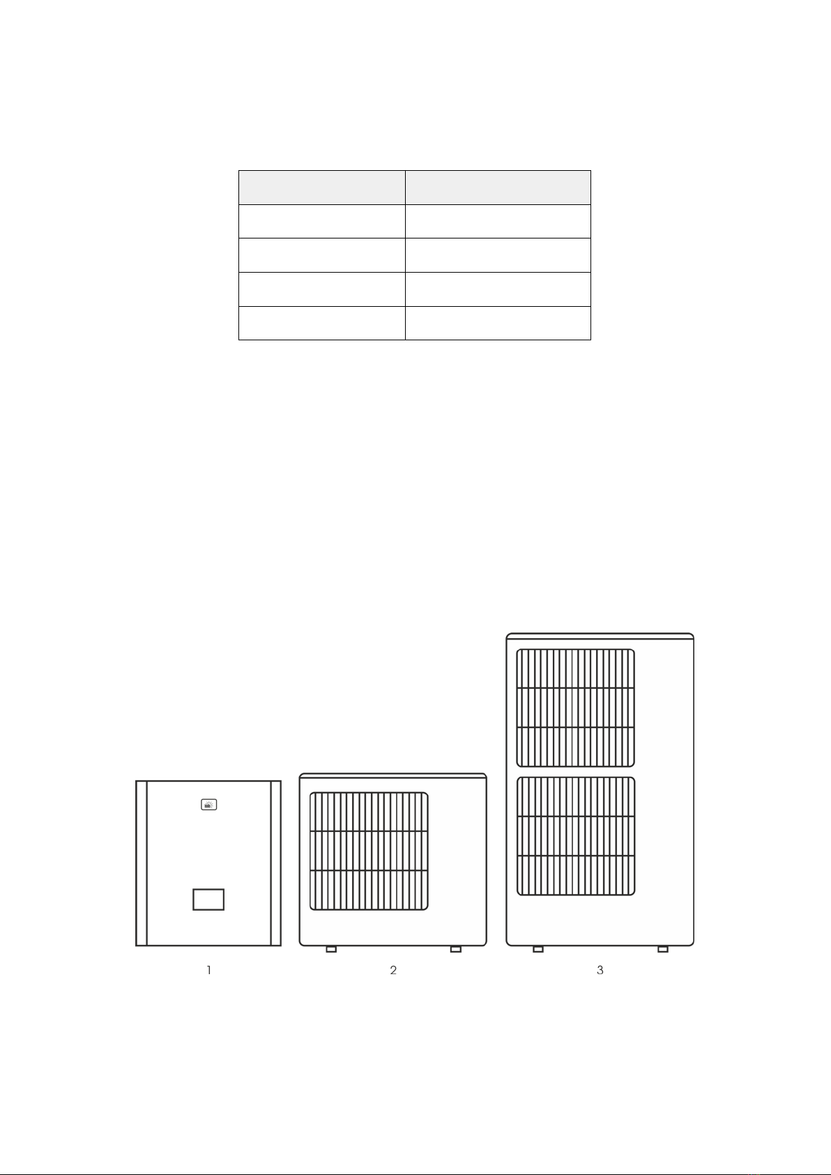
Figure .:- Indoor unit; - Single fan outdoor unit; - Double fan outdoor unit

.6 Table of technical parameters
Figure .: Table of technical parameters
. Principle of operation and correct use
.Principle of heat pump operation
The basic prerequisite for the operation of a heat pump is a heat transfer medium with suitable properties for changing
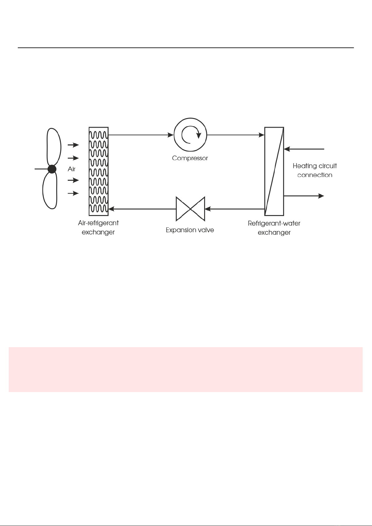
the state at a given pressure and temperature. All these basic components are indicated in the gure below – Schematic
diagram of the heat pump operation.
Figure .: Principle of heat pump operation
In the rst phase The refrigerant enters the air-refrigerant heat exchanger and changes its state to gas. As a result,
the refrigerant receives energy from the air. The refrigerant continues through the piping to the compressor, where it is
compressed. This converts it to a higher temperature level. The last phase is the transfer of the obtained energy to the
heating circuit in the refrigerant-water exchanger. Here, the gaseous refrigerant condenses and transfers energy to the
heating medium. The liquid refrigerant then passes through the expansion valve again and is again evaporated in the air-
refrigerant exchanger.
.Hot water heating systems
This section contains general facts of recommendations in the eld of heating systems. It cannot be used to design
a heating system. The system must always be designed by an experienced professional. Likewise, the choice of
the heat pump power and type must be made on the basis of a calculation of building’s heat losses by an expert.
The NeoRé series heat pump is designed for hot water heating systems. For this reason, some of them are described in
the following paragraphs. The characteristics of individual heating systems differ, and therefore must be taken into account
when choosing a heat pump, whether it is a new or existing heating system. In general, however, we can say that in a heating
system we try to maximize the surface area of the heater and thus reduce the temperature of the heating water required to
transfer the required amount of energy.

..Low-temperature heating system
Examples of a low-temperature heating system:
•oor heating
•ceiling heating/cooling
•wall heating
Large-area radiant systems are best suited for use with a heat pump. The heat pump is maximally efcient with these
systems and its service life is longer. They are also the most comfortable type of heating for habitable rooms.
With these systems, it is possible to induce natural thermal comfort and avoid heat build-up and large thermal differences
upwards, as is the case with traditional convective heating systems.
..Medium-temperature heating system
Examples of a medium-temperature heating system:
•radiators
•fan coils
This heating method is less advantageous when used with a heat pump, but still usable. The small radiant surface of the
radiator plates and thus the higher temperature requirement of the heating medium reduces the efciency of the heat pump.
The maximum heating water temperature for radiators is 55°C(60°C for HP). Using the maximum temperatures continuously
can reduce the service life of the product.
.Cooling system
The heat pump can also be used for cooling. For cooling, the outlet temperature is limited by the condensation tem-
perature in the given environment. The heat pump is not suitable for cooling with a cooling water temperature below the
condensation temperature, e.g. fan coils. Condensation occurs on the internal equipment of the indoor unit and leads to its
damage. A suitable cooling system is cooling ceilings where condensation does not occur.
.Correct principles of using a heat pump
A heat pump is a low-temperature heat source that pumps thermal energy between two temperature levels. Based on
physical principles, the more distant these levels are, the more energy must be put into the process. For higher efciency of
the heat pump, these levels have to be brought as close as possible.
In practice, this means that we have to keep the heating water temperature as low as possible and the outdoor air temper-
ature as high as possible. The outdoor air temperature can only be affected by the correct placement of the outdoor unit so
that it has a sufcient air supply (pay attention to installation in enclosed yards, valleys, etc.). The heating water temperature
can be affected by a correct design and use of the heating system.
It is more advantageous to use the heat pump to heat continuously to a lower heating water temperature than
spasmodically to a higher temperature, where the heat pump is less efcient.
. Description of the user interface
Before making changes to the device settings, carefully read what each function means and what the settings
affect. Improper adjustment can result in uncomfortable and uneconomical operation, which is associated with
unnecessarily higher equipment wear and higher operating costs.
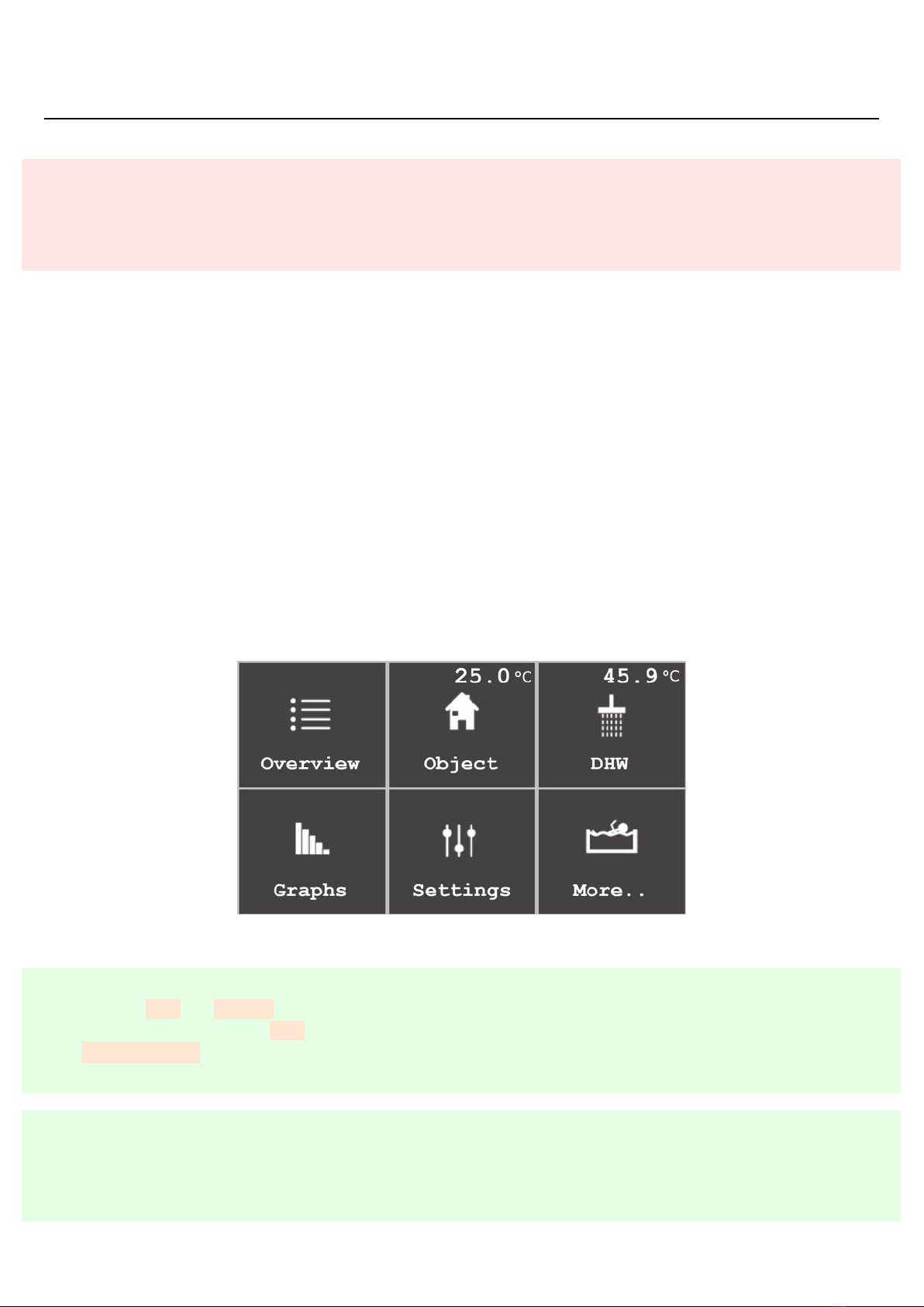
.Default screen
For the control, activation, deactivation and setting of the heat pump, use the touch screen on the front of the product
cover. The default screen (Fig. .Page ) offers six icons, each for controlling or setting one of the heat pump functions.
Overview is used for basic control of the device, activation of heating, DHW heating, overview of temperatures and energies,
list of status and error messages.
Object is used for advanced setting of the requirements for building heating or cooling.
DHW is used for advanced setting of the requirements for DHW heating, its circulation and disinfection.
Graphs displays the course of important temperatures
Settings is used for general setting of the device behaviour and remote access.
More is used to set additional systems such as a secondary source or pool circuit.
Figure .: Default screen of the touch screen
�Sections DHW and More.. are displayed only if the appropriate temperature sensors are connected. I.e. a DHW
temperature sensor for the DHW section and at least one of the storage tank or pool temperature sensors for the
More.. section.
�Elements on the display that can be used to change values, turn functions on and off or link to another page have
an orange background. Pressing the element displays the linked page or the panel for editing the variable, which
dynamically changes according to its type.
.Overview
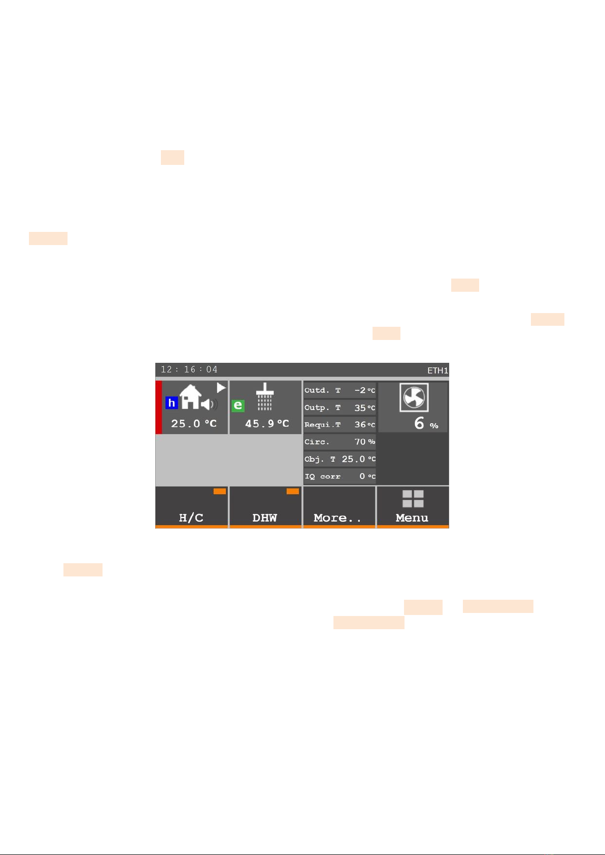
The overview screen (Fig. .page 6) is divided into four columns.
In the rst column from the left, there is a section at the top in which the heating mode is displayed (heating – red,
cooling – blue). Furthermore, it displays the current temperature of heating water, the operation of the circulating pump
using a triangular pictogram and whether the silent mode is active (speaker icon). In addition, the letter hmay appear here
if the cooling water temperature is automatically limited due to approaching the dew point.
At the bottom, there is the H/C control button that activates/deactivates the device. If the rectangle in the upper right is
orange, the device is operating, if the rectangle is grey, the function is switched off.
The second column shows the current temperature of domestic hot water (DHW) and, at the bottom, a button for switch-
ing DHW heating on and off. It also contains a signalling rectangle similar to the H/C button.
The third column shows a list of the most important temperatures and power of the circulating pump. Pressing the
More.. button displays the next screen containing a more detailed list of current temperatures and other device status
values.
The upper part of the fourth column shows whether heating uses the heat pump, bivalent or secondary source, percent-
age of the current heat pump power and other details about the current operating mode. The Menu button at the bottom
can be used to return to the default screen.
The time is displayed on the left side of the top bar. The right part may display two text abbreviations. If CLOUD is
displayed, the Neota Route remote management cloud service is activated. If ETH1 is displayed, the device is connected to
an Ethernet network and can be controlled within the local network using a computer, smartphone or tablet.
Figure .: Overview section
The More.. menu screen (Fig. .page ) displays a detailed list of sensed data about the device and its operation.
The upper left section displays information about the secondary circuit, the storage tank and the pool. The left centre section
displays data about the operation of the outdoor unit. Data displayed in the right section is identical to the overview screen.
The meaning of individual abbreviations is explained in Chapter ..(page ). Press Energy and Status Error to switch
to other screens. You can also nd the next screen under the button Hours in use (Fig. .page. ).
6
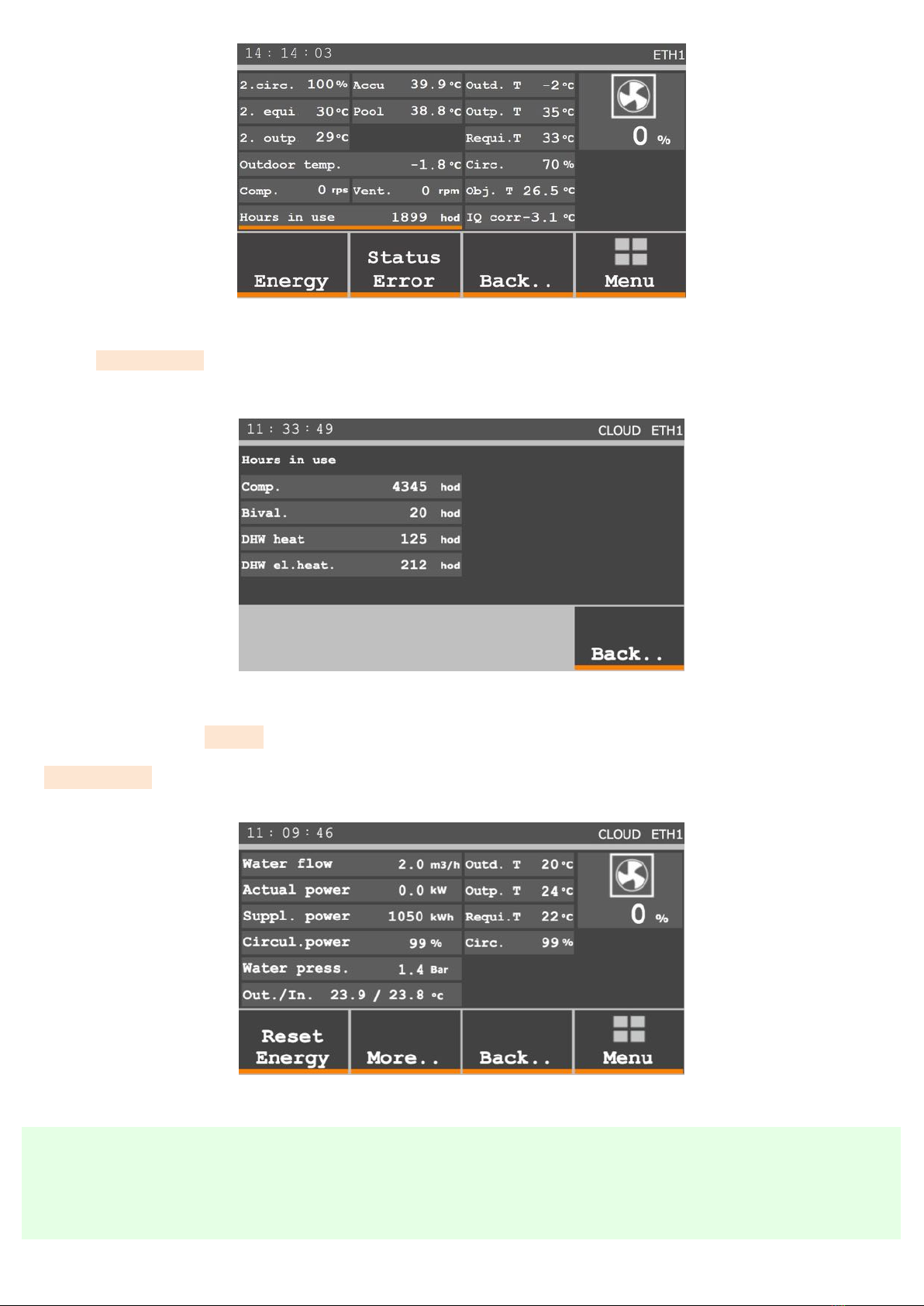
Figure .: Overview section More..
The Hours in use screen (g. .p. ) displays the counted running hours of the compressor (Comp.), bivalent source
(Bival.), DHW heating with a heat pump (DHW heat.) and DHW reheating with an electric heater (DHW el. heat.) including
disinfection.
Figure .: Overview section More.. Hours in use
The left part of the Energy screen (Fig. .page ) shows the quantities needed to calculate the current supplied
power, the current supplied power as well as a counter of the total supplied energy. This counter can be reset with the
Reset Energy button, e.g. before the start of the heating season. The right side of the screen is again identical to the
previous window.
Figure .: Overview section More.. Energy
�If the current power value is negative, heat is being removed from the building. This is common, for example, when
the outdoor unit is defrosting and an ice layer forms on the evaporator, which needs to be removed to maintain
good heat transfer. This is achieved by taking part of the energy of the building and heating this evaporator.
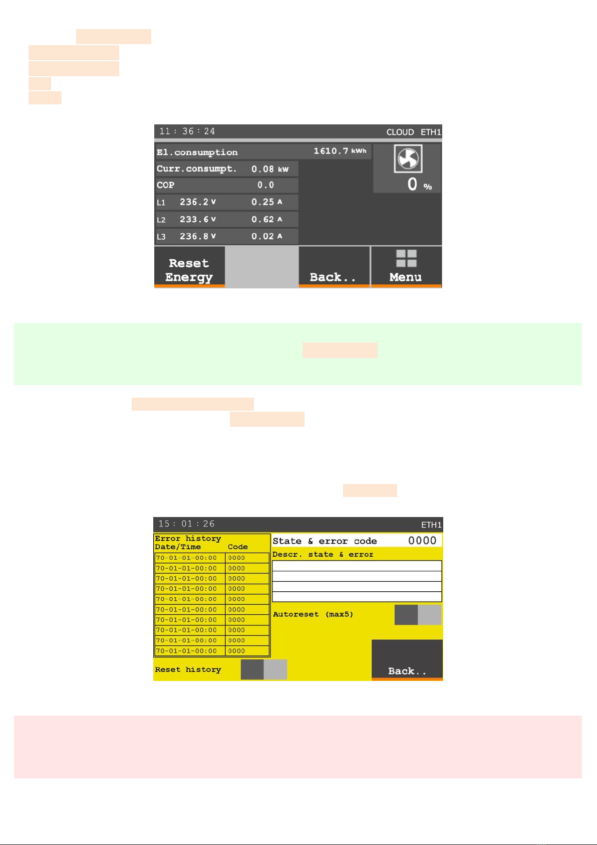
Screen Energy - More (Fig. .6 page 8) displays optional equipment data:
El. consumption - power consumption since the last energy reset.
Curr. consumpt. - current consumption averaged over the last minutes.
COP - current COP averaged over the last minutes.
L1-L3 - current state of voltage and current on individual phases.
Figure .6: Overview More.. Energy More..
�As standard, the values are not displayed on the screen Energy - More To display them, you need to purchase
an additional module.
The left part of the State and error screen (Fig. .page 8) shows a history of the last ten recorded problems.
You can clear the error history table using the Reset history button. This deletes data from the screen, but the complete
record of the operating data remains saved and is accessible from a web browser in the device settings.
The last fault that occurred is shown at the top of the right part of the screen. The white window below lists faults that
occurred and then disappeared. When a fault disappears, the device returns to normal operation thanks to the autoreset
function. However, this function resumes operation a maximum of times. If a fault occurs more than times, it is likely
a more serious problem that needs to be eliminated. You can use the Autoreset button to reactivate or deactivate this
function.
Figure .: Overview section More.. Error status
Stored operating data must never be deleted or modied. The data record is used to analyse the operation and
faults of the device. Damage or deletion of the records may affect the validity of warranty claims.
8

..Meaning of graphic symbols and text abbreviations
Heat pump operation – the heat pump is used for heating / cooling / DHW heating.
Secondary source operation – the secondary source is used for heating, the heat pump is used for DHW heating
Defrosting – the outdoor unit (exchanger) is defrosting, heating / cooling / DHW heating is interrupted
Outdoor air temperature too low – the outdoor temperature is lower than the permissible operating temperature,
the bivalent source (integrated electric boiler) is completely used for heating and DHW heating
Economical operation – the icon is displayed if the output water temperature is lower than 45°C and the outdoor
unit power is lower than %
DHW optimization - the icon is displayed if the DHW optimization function is active, i.e. out of the set time
periods for Required DHW temperature
DHW heating is blocked by the time schedule – in the DHW DHW heating time schedule section, DHW heating
is not enabled for this time
Antilegionella – the DHW tank is electrically heated to eliminate Legionella (disinfection of the hot water tank
by a temperature of 60°C)
Protection of the outdoor unit exchanger from damage – in case of frost protection or low water ow through
the indoor unit, the outdoor unit is shut down for minutes.
Activated limitation of the cooling water temperature when it is approaching the dew point.
Activated silent mode.
PPV optimization enabled, PPV signal inactive.
Activated PPV signal.
Attenuation – Attenuation is active, the parameters can be set in the Building Attenuation time schedule section
High tariff – device operation is blocked due to a high energy tariff
DHW heating – the DHW tank is being heated by the heat pump
DHW el. heating – the DHW tank is being heated by the electric heater
Drying – activated oor drying mode
Pool heating – the pool circuit is being heated by the heat pump
Bival st st. nd st. – the bivalent source (integrated electric boiler) is running (st st. – rst stage; nd st. – second stage)
Outd.T – outdoor air temperature
Output – output (heating) water temperature
Weather compensation – temperature calculated by the weather compensation curve for the main circuit
Circulation – circulating pump power percentage
Building – air temperature in the reference room of the building

IQ cor. – correction value applied to the weather compensation curve
nd circuit – opening value of the secondary circuit mixing valve
W.com. – temperature calculated by the weather compensation curve for the secondary circuit
Outp. – temperature of the output (heating) water for the secondary circuit
Outdoor temperature – outdoor air temperature
Comp. – current compressor speed
Vent. – current fan speed
Hours in use – number of operating hours of the device
Water ow – current water ow in the indoor unit
Current power – current heat output supplied by the heat pump
Suppl. power – total heat output supplied from the last energy reset
Circul. power – circulating pump power percentage
Water press. – current water pressure in the heating system
Out./In. – temperature of the output (heating) water / temperature of the return water
�The meaning of error codes is described in a separate chapter – Faults and status messages (page ).
This manual suits for next models
8
Table of contents
Other NeoRe Heat Pump manuals


Popular Heat Pump manuals by other brands

alphainnoTec
alphainnoTec SW 232H3 operating manual

mundoclima
mundoclima MUP-HK Series owner's manual

Water Furnace
Water Furnace Envision NRAC026 installation manual

Cooper & Hunter
Cooper & Hunter UNITHERM3 R32 owner's manual

Astral Pool
Astral Pool BDP Series manual

Water Furnace
Water Furnace 7 Series manual

Astral Pool
Astral Pool PRO ELYO INVERBOOST NN User and service manual

Glowworm
Glowworm Envirosorb 5 Installation and servicing

Waterco
Waterco Ultra User and care guide manual

vacuubrand
vacuubrand Peltronic Instructions for use

Carrier
Carrier AQUAZONE 50KQL07-19 Product data

Nortek
Nortek BDFC-2.8-AK owner's manual


